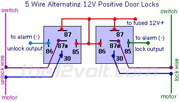
After much reading I think I have type c door locks. The wiring diagram here says light blue/ black are the wires for the locks and are in the kick panel. I have found them. Checking these wires with a meter shows both wires at ground so ground either or both does nothing. If I were to apply positive to either it would be a dead short. Diagrams I am looking at show not just tapping into the wires but cutting the wires and sending them threw a relay. Is the two wires in the kick panel the wires between the switch and the motor. If they are when I cut them two of the ends should still read ground and the other two should be open and the two opens would be the ones going to the motor and by applying 12 volts to the here in opposite directions would lock/unlock the doors. Am I getting this or have I got this all messed up?
Yes, if you cut the wires the wires that remain grounded are the switch side, the "open" side is the actuator.
The actuator works by applying 12vdc across the coil. If you apply it the voltage one way the actuator will move in, if you apply voltage the other way it will move out. To make this easy the OEM rests both legs at ground and then when you hit the switch it opens the respective leg (thus breaking the ground on that leg) and supplies 12vdc to the actuator.
By adding relays you will use the normally closed contacts (87A and 30) so that the actuator will rests at ground. When you energize the relay it will switch on and break the connection to ground and replace it with 12vdc.
-------------
Kevin Pierson
In a 1993 Corvette the door switches are a positive trigger to the Passive Keyless Entry Module. Both functions rest at ground. The desired function goes positive, while the opposite remains at ground. It is not a polarity reversing system. Just positive trigger. The module performs the actuator switching and polarity reversing.
Cut the small black and small blue wires coming from the drivers side switch. In the diagram below the switch wires come from the switch. The "motor" wires go to the RKE Modle (towards the interior of the car)
Use this diagram:

Trivia few owners know about regarding Late (91-96) C4 Corvettes.
Open a window, or have the roof off or top down so you can't lock the keys in it.
Leave the ignition key IN the ignition switch.
Lock the doors with the power door locks.
Close both doors.
When the second door closes, the locks will un-lock.
The BCM won't let you lock the doors with the key in the ignition.
Ok I am Stumped. I understand how the Diagram in the post above works but here is the problem. I have cut the blue and black wires going in the kick panel with the blue disconnected the door does not lock with the black disconnected it will not unlock so I got the lock/unlock wires.
Checking with a meter both sides of either cut wire rest at ground. If I try to activate either the door side changes to positive and ground is removed from the vehicle side. The diagram above does nothing for removing the ground from vehicle side. activating the relay just immediately pops a 10 amp fuse as I am just sending power straight to ground.
