2011 camry with cm6200 and blade al
Printed From: the12volt.comForum Name: Car Security and Convenience
Forum Discription: Car Alarms, Keyless Entries, Remote Starters, Immobilizer Bypasses, Sensors, Door Locks, Window Modules, Heated Mirrors, Heated Seats, etc.
URL: https://www.the12volt.com/installbay/forum_posts.asp?tid=136003
Printed Date: April 04, 2026 at 1:38 PM
Topic: 2011 camry with cm6200 and blade al
Posted By: jp2891
Subject: 2011 camry with cm6200 and blade al
Date Posted: February 05, 2014 at 4:55 PM
Starting with the BLADE-AL installation manual, there are about 5 wiring connections from the BLADE-AL wiring harness. I've attached the wiring diagram from the BLADE-AL manual:
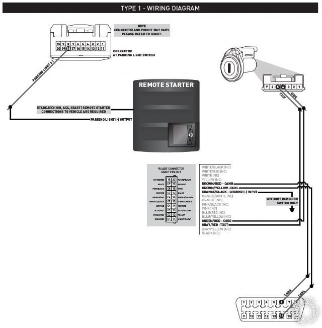
The connection information for the BLADE-AL wiring harness is stated as follows in the BLADE-AL manual. The information is listed in the order of: "BLADE PIN#-BLADE WIRE COLOR-ITEM-FACTORY CONNECTOR INFO-FACTORY PIN POSITION-FACTORY WIRE COLOR-LOCATION".
Pin 1 Gray/Red TXCT 7 Pin Connector Pin 5 Red Immobilizer (Ignition switch per diagram)
Pin 2 GREEN/ Red CODE 7 Pin Connector Pin 4 Brown Immobilizer (Ignition switch per diagram)
Pin 5 ORANGE / Black GROUND INPUT (-) Only if I don't use a Hood Pin
Pin 6 BROWN / Red CANH 16 Pin Connector Pin 6 Black OBDII
Pin 16 BROWN / Yellow CANL 16 Pin Connector Pin 14 White OBDII
Following is a picture of the wiring callout from the BLADE-AL manual.
My next questions are in regards to the actual CM6200 wiring. Following is a picture of the wiring requirements from the CM6200 manual:
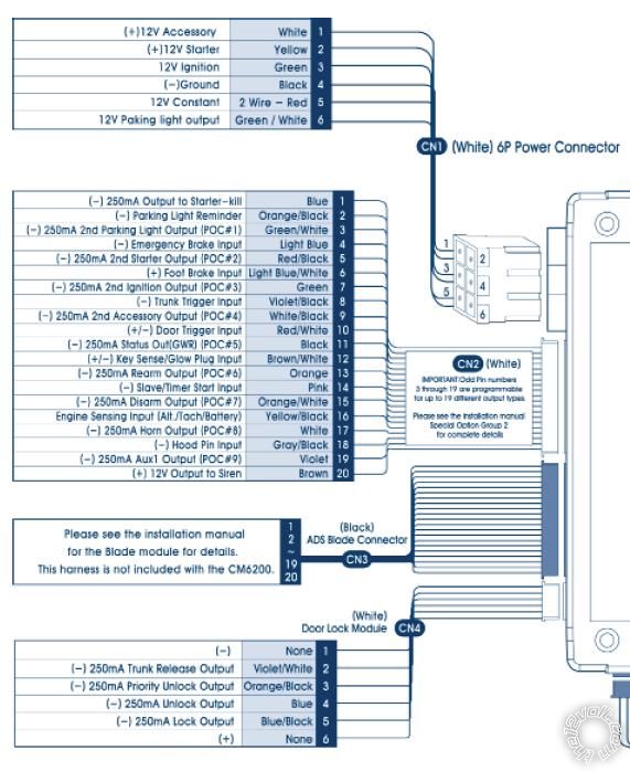
In regards to the CM6200 wiring diagram, following is my understanding of the additional wiring needed beyond the BLADE-AL wiring harness. My questions here have to do with getting direction on where to best find some of the factory wires to tie into and if I need the specific connection or not. Please feel free to correct the factory wire location listed below if I don't have it correct. The information is listed in order of "CM6200 CONNECTOR PIN#-WIRE COLOR-DESCRIPTION-LOCATION TO LAND WIRE (FACTORY WIRE COLOR-FACTORY PIN#)". I'll go over it for each connector:
CN1 (6P Power Connector):
Question #1: What color and pin is the starter wire coming from the factory ignition harness to tie into the starter relay?
Pin 1 White (+) 12V Accessory Ignition Harness (Wire Color? Pin?)
Pin 2 Yellow (+) 12V Starter Prewired to anti-grind/starter-kill relay in CM6200 kit
Pin 3 Green #1 12V Ignition Ignition Harness (Wire Color? Pin?)
Pin 3 Green #2 12V Ignition Prewired to anti-grind/starter-kill relay in CM6200 kit
Pin 4 Black Ground (-) Somewhere on firewall with a good ground
Pin 5 Red #1 12V Constant Location? Wire Color? Pin?
Pin 5 Red #2 12V Constant Location? Wire Color? Pin?
Pin 6 GREEN / WHITE Parking Light Output (+) Not Used based on BLADE-AL diagram stating I need to wire the Parking Light Output (-) for my vehicle.
CN2 (20P Input/Output Connector):
Question #2: Do I need to wire the "2nd Ignition/Starter/Accessory" relay harness if I'm not using it to power a secondary starter/ignition/accessory or is this optional?
Question #3: Where can I find the Parking Light Switch location or at least the location of the Parking Light Switch wire to tie into?
Pin 1 Blue Output to Starter Kill (-) Prewired to anti-grind/start-kill relay in CM6200 kit
Pin 2 ORANGE / Black Parking Light Reminder (-) Input Do I need this?
Pin 3 GREEN / WHITE Parking Light Output (-) Where is Parking Light Switch location?
Pin 4 Light Blue E Brake Covered by BLADE-AL
Pin 5 RED / Black - 2nd Starter Output (-) Do I need this?
Pin 6 Light Blue/White Brake 12V Input (+) Covered by BLADE-AL
Pin 7 Green 2nd Ignition Output (-) Do I need this?
Pin 8 Violet/Black Trunk Trigger Input (-) Covered by BLADE-AL
Pin 9 WHITE/ Black 2nd Accessory Output (-) Do I need this?
Pin 10 RED / White Door Trigger Input (+/-) Covered by BLADE-AL
Pin 11 Black Status/GWR Output (-) Covered by BLADE-AL
Pin 12 BROWN / White Key Sense/Glow Plug Do I need this?
Pin 13 Orange Rearm Output (-) Covered by BLADE-AL
Pin 14 Pink Slave/Closed Input (-) Do I need this?
Pin 15 ORANGE / White Disarm Output (-) Covered by BLADE-AL
Pin 16 Yellow/Black Engine Sense/Tach Input Covered by BLADE-AL
Pin 17 White Horn Output (-) Do I need this?
Pin 18 Gray/Black Hood Pin Input (-) Does my Camry have a factory Hood Pin? If not, I may install the Hood Pin that comes in the CM6200 kit. Otherwise I'll ground Pin 5 on the BLADE-AL harness.
Pin 19 Violet Aux1 Output (-) Do I need this?
Pin 20 Brown 12V Siren Output (+) Do I need this?
CN4 (6P Door Lock Module): My understanding is that all of these connections are covered by the BLADE-AL. Is this correct?
Replies:
Posted By: kreg357
Date Posted: February 05, 2014 at 6:14 PM
OK. I like your through preliminary work on this project. It truely is "all in the planning".
The CM6200 and Blade AL is a great combination. Very compact and reliable. The Blade AL needs to flashed with the DL TL1
firmware while inserted into the CM6200. This requires the ADS USB cable and access to the Flash section of their WEB site.
When you do this, it will also update the firmware on the CM6200 ( if necessary ) and allow you to set the CM6200 programming
options.
For vehicle wiring, here are some sources :
Here is a link to Bulldog Security : https://www.bulldogsecurity.com/bdnew/vehiclewiringdiagrams.asp
Here is a link to Ready Remote : https://www.readyremote.com/main.asp
Here is a link to AudioVox : https://techservices.audiovox.com/AccessRequest.aspx Sign-up & info is free.
Your next step is to download all the wire guide info you can from as many sources as possible. Compare them as there
probably will be differences. Consolidate everything on a cheat sheet. You will use this as your guide during the install.
The Blade w/TL1 will handle a bunch of things for you. They are listed on Page 2 of the install guide. The Type 1 Wiring Diagram
gives you most of the rest of the wiring. You car has a few exceptions in it.
You will notice that the wiring guides list two Starter wires, two Ignition wires and one Accessory wire at the main ignition switch
harness. You should power all these wires separately. The CM6200 only has one of each at the CN1 connector and an extra 30/40
Amp Bosch style relay, with harness, for one additional ignition circuit. You can use this for the Starter2 circuit and buy an additional
relay for the Ignition2 circuit. The control for these external relays will be the CN2 Pin 5 and Pin 7.
Pin 1 White (+) 12V Accessory white + ignition switch, white 8 pin plug, pin 2
Pin 2 Yellow (+) 12V Starter blue + ignition switch, white 8 pin plug, pin 7
Pin 3 Green #1 12V Ignition yellow + ignition switch, white 8 pin plug, pin 6
Pin 4 Black Ground (-) chassis ground
Pin 5 Red #1 12V Constant black (30A) + ignition switch, white 8 pin plug, pin 5
Pin 5 Red #2 12V Constant black (30A) + ignition switch, white 8 pin plug, pin 5
Pin 6 GREEN / WHITE Parking Light Output (+) Not Used
Pin 1 Blue Output to Starter Kill (-) Prewired to anti-grind/start-kill relay in CM6200 kit
Pin 2 ORANGE / Black Parking Light Reminder (-) Input Not used ( used w/manual trans )
Pin 3 GREEN / WHITE Parking Light Output (-) black (-) @ headlight switch, white 20 pin plug, pin 18
Pin 4 Light Blue E Brake Covered by BLADE-AL
Pin 5 RED / Black - 2nd Starter Output (-) Use with supplied extra relay for Starter2
Pin 6 Light Blue/White Brake 12V Input (+) Covered by BLADE-AL
Pin 7 Green 2nd Ignition Output (-) Used with additional relay for IGN2
Pin 8 Violet/Black Trunk Trigger Input (-) Covered by BLADE-AL
Pin 9 WHITE/ Black 2nd Accessory Output (-) not used
Pin 10 RED / White Door Trigger Input (+/-) Covered by BLADE-AL
Pin 11 Black Status/GWR Output (-) Covered by BLADE-AL
Pin 12 BROWN / White Key Sense/Glow Plug Not Used
Pin 13 Orange Rearm Output (-) Covered by BLADE-AL
Pin 14 Pink Slave/Closed Input (-) Not used
Pin 15 ORANGE / White Disarm Output (-) Covered by BLADE-AL
Pin 16 Yellow/Black Engine Sense/Tach Input Covered by BLADE-AL Do Tach Learn process
Pin 17 White Horn Output (-) white to black (-) @ horn switch Optional
Pin 18 Gray/Black Hood Pin Input (-) test for Factory Hood Pin
Pin 19 Violet Aux1 Output (-) Not Used
Pin 20 Brown 12V Siren Output (+) Not Used
Ignition2 relay wiring
Relay Pin 85 to CM6200 CN2, Pin 7, Green
Relay Pin 86 and 87 to Camry black (30A) (+) ignition switch, white 8 pin plug, pin 5
Relay Pin 30 to Camry IGN2, pink (+) ignition switch, white 8 pin plug, pin 1
Relay Pin 87a not used
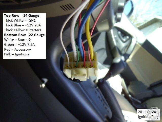
Here is a photo of the Headlight connector in the steering column of a 2011 RAV4 :
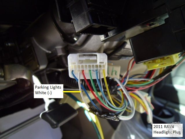
It is a White 20 Pin connector but the Parking Light wire at Pin 18 is White, your Camry's wire will be Black.
If you want photos of these wires, Fortin has a optional service called WireColor that should provide pictures of most
of these wires. They change a $5 per vehicle fee. Here is a link : https://wirecolor.com/en/
-------------
Soldering is fun!
Posted By: jp2891
Date Posted: February 07, 2014 at 9:24 AM
Thanks kreg357. The information clears up a lot of questions. The links to the wiring guides are great. I pulled out the Haynes manual for the Camry as another source, but they put such little useful information in those regarding wiring.
I plan on adding fuses to the relay wiring (to wires on relay pins 85 & 30). Do you have a suggestion as to the size of the fuses needed for each relay (primary, secondary starter, secondary ignition)? All 30A?
Primary Relay Pin 86 (Ignition Wire) Fuse Size: ?
Primary Relay Pin 30 (Starter Wire) Fuse Size: ?
Secondary Igniition Relay Pin 86/87 (12V+ Wire) Fuse Size: ?
Secondary Ignition Relay Pin 30 (Iginition#2 Wire) Fuse Size: ?
Secondary Starter Relay Pin 86/87 (12V+ Wire) Fuse Size: ?
Secondary Starter Relay Pin 30 (Starter#2 Wire) Fuse Size: ?
Also, one more concensus question. I will test all wires to properly identify each wire for it's use. Once I have identified and labeld them, I will start the physical installation phase. My question: Is it good practice to remove the negative (-) connection on the battery during stripping and soldering of the wires? I haven't typically done this in the past, but then again most of my projects have been "plug-n-play".
Posted By: jp2891
Date Posted: February 07, 2014 at 10:24 AM
Posted By: kreg357
Date Posted: February 07, 2014 at 1:18 PM
Re Relay fusing : The +12V constant supply at the Camry's main ignition connector is rated at 30 Amps. I would check the wire
gauge of the Starter2 and Ignition2 wires and fuse both relay's accordingly. Using the supplied / pre-wired wired relay and replacing
its' 30 Amp fuse with a more appropriate sized fuse ( 10A ? ). Same for the additional relay, on its' Pin 86 / 87 feed. I don't see any
need to fuse the Pin 30 output side.
While the CM6200 system is not an alarm system ( no siren ) and you are using the (-) Parking Light wire, you might check for
a very thick wire at the front of the dash fuse box. If this wire is there, consider splitting the R/S systems load between these
two +12V constant wires ( fuse box & ignition harness ).
As for disconnecting the vehicles battery during install, well, it all has to do with the vehicle and your comfort level. Most installer's
never disconnect the battery during the install. Of course, doing it like that, you should not disconnect any connectors ( other
than the main ignition connector, if necessary ) and you must be very careful while making the connections ( not shorting anything
to chassis ground ). Depending on the vehicle, disconnecting the vehicles battery will lose the radio presets, radio security code
( if used ) and set a "Not Ready" in the computer, which can cause a failure/delay/return with some state's emissions inspections.
If you don't mind the radio reset and aren't getting a state inspection for a few weeks, by all means, disconnect the battery after
you have found and marked all the necessary wires.
-------------
Soldering is fun!
Posted By: jp2891
Date Posted: February 08, 2014 at 10:44 AM
Curiosity question: why does the CM6200 use the two red wires for the 12V+ at CN1-Pin 5? Is it that the potential current draw would be to much on one wire, so they split it across two wires? Or is the second wire a possible circuit for a back up battery? Since the two red wires both land on Pin 5, they must be common inside of the CM6200.
In regards to the fusing, my Haynes manual shows a 7.5A fuse on the Starter2 circuit. Definitely less than the 30A fuse that comes on the relay harness with the CM6200. I'll check the Ignition2 circuit and wire gauge to size that fuse.
One more question to kreg357. When you commented on splitting the 12V+ loads, you stated "While the CM6200...and you are using the (-) Parking Light wire..." Just curious as to what is unique about the (-) Parking Light wire vs any other (-) wire since you made note of the (-) Parking Light wire.
Posted By: kreg357
Date Posted: February 08, 2014 at 11:28 AM
Re (-) Parking Light : Other than the ignition wires, the only other possible big load on the CM6200 is a (+) Parking Light wire. On some vehicles, they get near 8 Amps. Using a low current (-) Parking Light wire makes the overall load much less.
Re CM6200 CN1-5 : Each Red wire is of sufficient gauge to handle 30 Amps. Once they get to the metal connector and the CM6200 internal bus, it is 60 Amp capable. Just saves on plug size and number of connector pins. That does explain why the outputs are also fused.
If the 2011 Camry is similar to the 2011 RAV4 pictured below, there might be a few 7.5 Amp wires in the harness.
-------------
Soldering is fun!