2012 silverado, viper 5204
Printed From: the12volt.com
Forum Name: Car Security and Convenience
Forum Discription: Car Alarms, Keyless Entries, Remote Starters, Immobilizer Bypasses, Sensors, Door Locks, Window Modules, Heated Mirrors, Heated Seats, etc.
URL: https://www.the12volt.com/installbay/forum_posts.asp?tid=136007
Printed Date: April 04, 2026 at 8:41 AM
Topic: 2012 silverado, viper 5204
Posted By: hzhardy
Subject: 2012 silverado, viper 5204
Date Posted: February 06, 2014 at 12:15 PM
I am installing a viper 5204 and db-all using the rf loop. I understand the wiring for the most part with exception of the ignition output and diode. it is throwing through a loop as it show the ignition output from the remote start module to the ignition through a diode. the way dei's diagram shows the diode it would prevent the current from the module to go to the ignition line. I know I may be over thinking this, but i want to be sure. there is also two ign out puts are on the heavy connector, which leads me to believe the input would also have to be connected, then there is a flex relay out put on the h2 connector that is a negative trigger. I will stop rambling and I appreciate your help.
Replies:
Posted By: hzhardy
Date Posted: February 06, 2014 at 1:22 PM
also i am doing wire to wire
Posted By: smokeman1
Date Posted: February 06, 2014 at 8:43 PM
I believe the ignition output will come from the DB-ALL Blue connector (14 pin), pin 8, yellow to truck ignition. I does look a bit confusing.
You would be connecting the Pin 9, Pink (10 pin connector) to the Viper H3/1 Pink Ignition 1 Output.
-------------
When all else fails, Read the Instructions
Support the12volt.com Make a Donation
Posted By: hzhardy
Date Posted: February 07, 2014 at 12:15 PM
i guess were i am confused is if i do decide to go d2d would the diode even since necessary since the diode would block any output voltage from the 5204 so it would not do anything.
other than the wiring aspect what is the advantage of d2d or w2w?
Posted By: smokeman1
Date Posted: February 07, 2014 at 7:59 PM
Going D2D, you would still need all of the solid line connections, including the diode. D2D does all of the dashed lines, except the TACH sometimes. I have had some DB-ALL pick up the TACH and some did not.
Some people report having issues with D2D. I have only done one in D2D mode as an experiment so to speak. Not sure if it has an issue or not. The DB-ALL lost it's programming after the Jeep battery went dead in this very cold winter. A three minuet reprogram. D2D problem? Not sure yet.
All of my other installs have been W2W. Have had no issues with any of those installs.
So in short it's a your preference.
It does not take much more to do W2W.
-------------
When all else fails, Read the Instructions
Support the12volt.com Make a Donation
Posted By: pentavolvo
Date Posted: February 07, 2014 at 8:41 PM
Tach from dball does work on silverado as info
Posted By: hzhardy
Date Posted: February 08, 2014 at 9:23 AM
[QUOTE=smokeman1] Going D2D, you would still need all of the solid line connections, including the diode. D2D does all of the dashed lines, except the TACH sometimes. I have had some DB-ALL pick up the TACH and some did not.
Some people report having issues with D2D. I have only done one in D2D mode as an experiment so to speak. Not sure if it has an issue or not. The DB-ALL lost it's programming after the Jeep battery went dead in this very cold winter. A three minuet reprogram. D2D problem? Not sure yet.
All of my other installs have been W2W. Have had no issues with any of those installs.
So in short it's a your preference.
It does not take much more to do W2W.[/QUOTE
it is just weird how the have the diode set. the diode would not let current flow from the alarm to the ignition lines the way the diode is depicted. I am just confused as it is a dead end since it goes dotted from there to the dball
Posted By: hzhardy
Date Posted: February 08, 2014 at 9:28 AM
it just looks like its whole purpose was to be able to send the dball a ignition source from the remote start or ignition switch but not back feed the ignition lines from the remote start during it's start up sequnece
Posted By: flobee4
Date Posted: February 08, 2014 at 1:35 PM
yes the diode is necessary on the heavy gauge pink ignition 1 output. That pink wire is not only an output, but an input as well. When you goto program the tach or extra remotes the Pink wire needs to "see" the ignition is on. The bypass manufacturer doesn't want the heavy gauge Pink wire to be involved in starting the car, therefore they don't want the pink wire outputting anything. But the remote starter manufacture needs it to be powered up to sense when the ignition is turned on. That's why the diode is there, to block the output to the car, but allow the input from the car to the remote starter for programming purposes on the remote starter. Long story short, Pink Wire needs to be hooked up through diode. Make sure diode is facing correct way.
Posted By: hzhardy
Date Posted: February 08, 2014 at 4:21 PM
flobee4 wrote:
yes the diode is necessary on the heavy gauge pink ignition 1 output. That pink wire is not only an output, but an input as well. When you goto program the tach or extra remotes the Pink wire needs to "see" the ignition is on. The bypass manufacturer doesn't want the heavy gauge Pink wire to be involved in starting the car, therefore they don't want the pink wire outputting anything. But the remote starter manufacture needs it to be powered up to sense when the ignition is turned on. That's why the diode is there, to block the output to the car, but allow the input from the car to the remote starter for programming purposes on the remote starter. Long story short, Pink Wire needs to be hooked up through diode. Make sure diode is facing correct way.
do i need to take the input to power?
Posted By: hzhardy
Date Posted: February 08, 2014 at 4:31 PM
hzhardy wrote:
flobee4 wrote:
yes the diode is necessary on the heavy gauge pink ignition 1 output. That pink wire is not only an output, but an input as well. When you goto program the tach or extra remotes the Pink wire needs to "see" the ignition is on. The bypass manufacturer doesn't want the heavy gauge Pink wire to be involved in starting the car, therefore they don't want the pink wire outputting anything. But the remote starter manufacture needs it to be powered up to sense when the ignition is turned on. That's why the diode is there, to block the output to the car, but allow the input from the car to the remote starter for programming purposes on the remote starter. Long story short, Pink Wire needs to be hooked up through diode. Make sure diode is facing correct way.
do i need to take the input to power?
or does it only need to see the back feed from the ignition
Posted By: flobee4
Date Posted: February 08, 2014 at 5:03 PM
Ok I would put the diode inline with the thicker pink ignition 1 wire coming off the remote starter brain closer to the remote starter brain but still a few inches away. Then I would take your thin pink ignition input from the DB-all and tap it into the the diode side of the thicker pink wire that is closer to the brain. Then take the yellow ignition output from the dball and connect to the thicker pink wire on the diode side going away from the brain.
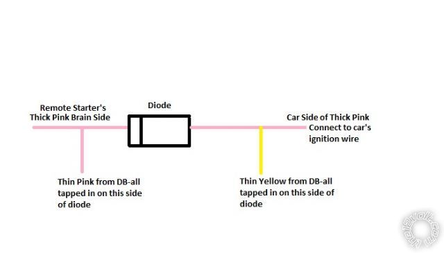
Hopefully my diagram helps you better understand...
Posted By: hzhardy
Date Posted: February 08, 2014 at 11:41 PM
ok it is all wired w2w, two questions. Are the heavy gauge inputs needed for my install? and since my truck does not have a factory hood pin do i need to take that wire to ground even through the schematic does not show it? I crimped on delphi gt series pins so most of my connections to my truck will plug into my junction block except my accessory and parking lights. I was going to take my accessory to the jb but in the wiring diagram for the truck is shows the ignition supply voltage teeing off to the theft module then through the bcm unless you guys have had success tying into the accessory else were. I guess it turned out to be three questions
Posted By: hzhardy
Date Posted: February 08, 2014 at 11:46 PM
Posted By: hzhardy
Date Posted: February 08, 2014 at 11:47 PM
Posted By: hzhardy
Date Posted: February 08, 2014 at 11:50 PM
Posted By: hzhardy
Date Posted: February 08, 2014 at 11:51 PM
Posted By: hzhardy
Date Posted: February 08, 2014 at 11:52 PM
i de pinned all the extra wires
Posted By: flobee4
Date Posted: February 09, 2014 at 3:27 AM
Yes you'll need the de-pinned heavy gauge power supply wires h3/6 & h3/9. You need the H1/1 wire connected as well.
It really doesn't matter where you get Constant power from as long as ot can supply the amperage needed. I usually get it from the BCM, there are a few RED / whites fused at 15 amps there. I know the junction box against the firewall inside the Cab has some constant 12volt supply as well as accessory, ground, and whatnot.
As for the accessory wire, I would just get it where they recommend. Why try to reinvent the wheel? The Truck is a very easy install with the bypass module, try not to over think it, just follow the diagram.
The pictures of your diode with the pinks and yellow wire soldered was exactly how I would do it. The downgrade to the thinner yellow wire was perfect since the wires at the ignition switch are thin as well.
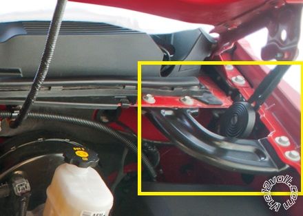
Do not ground the hood pin input, the viper will think the hood is open if you ground it and will not start. Run the wire out under the hood and install the hoodpin. I install it on the drivers side of the engine compartment down near where the air cartridge for the hood is. There is a U shaped bracket that goes from the fender to the firewall. I borrowed this picture from the internet:
Posted By: hzhardy
Date Posted: February 09, 2014 at 7:49 AM
flobee4 wrote:
Yes you'll need the de-pinned heavy gauge power supply wires h3/6 & h3/9. You need the H1/1 wire connected as well.
It really doesn't matter where you get Constant power from as long as ot can supply the amperage needed. I usually get it from the BCM, there are a few RED / whites fused at 15 amps there. I know the junction box against the firewall inside the Cab has some constant 12volt supply as well as accessory, ground, and whatnot.
As for the accessory wire, I would just get it where they recommend. Why try to reinvent the wheel? The Truck is a very easy install with the bypass module, try not to over think it, just follow the diagram.
The pictures of your diode with the pinks and yellow wire soldered was exactly how I would do it. The downgrade to the thinner yellow wire was perfect since the wires at the ignition switch are thin as well.
Do not ground the hood pin input, the viper will think the hood is open if you ground it and will not start. Run the wire out under the hood and install the hoodpin. I install it on the drivers side of the engine compartment down near where the air cartridge for the hood is. There is a U shaped bracket that goes from the fender to the firewall. I borrowed this picture from the internet:
thanks a lot for the help, i have been trying to follow the diagram from xpress kit to a t but there seems to be a bit of missing information as it did not show anything about the red and RED / black heavy inputs which did not make sense as see that connector like a relay bank. Hell it didn't even show the hood pin unless you looked at a standalone install. That must be good ole DEI with the secrets to try and keep people with their dealers lol
Posted By: hzhardy
Date Posted: February 09, 2014 at 7:52 AM
besides the safety aspect so I can run with out a hood pin until i get a Escalade latch (has a built in hood pin) or similar
Posted By: flobee4
Date Posted: February 09, 2014 at 8:39 AM
Yes just don't ground the hood pin wire, leave it disconnected. Do you have the BLACK/ white neutral safety wire permanently grounded as well? Also you NEED to have the toggle switch plugged in and I believe flipped to the on position. I do believe I see those things done in the picture, just making sure. Oh and the default programming for the Viper is for a manual transmission. You have to change Menu 3,1 to Automatic before you try to remote start the vehicle.
Did you check for a factory hood pin wire and test to see if you have one already installed? Its pink/black at the BCM Black plug, pin 17. The black BCM plug is also where the RED / White 15 amp constant power is as well. Pins 1, 2, 3, 4 are individually fused at 15 amps each. To test the pink/black hood pin wire in the car, put your meter's red probe on a known 12 volt source(such as the RED / white wires) then take your black probe and put it on the pink/black wire. with the hood closed you should be at 0 volts and with the hood open, your meter will goto 12 volts.
As for the guides, you should be using the viper guide and then the DB-all as a supplement guide specific to your car. So if the viper says you need to connect a brake wire for shutdown, you would assume it needs to be connected straight to the car. Then you look at the db-all guide and see if it supplies a brake output, if it does then the viper brake goes to the db-all. For the parking light wire, you would assume the same, then look at the db-all guide. the dball doesn't have a parking light hookup, so its got to go directly to the vehicle. etc...
Posted By: hzhardy
Date Posted: February 09, 2014 at 8:53 AM
well that is my problem I only have the viper install manual and nothing vehicle specific lol. as for the hood pin my truck does not have it since it is a single cab ls. they only came on the higher tier trucks with factory alarms. For the toggle switch I just soldered the two leads together since I did not want a toggle switch in or under the dash. The neutral safety is soldered together with the ground from the alarm and db all. If i take my unit to a install can i have them write my options with bit writer outside of my truck and not loose the programing? I have the XKloader, but I do not believe it works for the alarms
Posted By: flobee4
Date Posted: February 09, 2014 at 9:11 AM
You can have someone program the Viper with the BitWriter for you by just applying Power to the red wires and ground to the viper brain. I do it all the time while bench prepping. I have a 12 volt power supply on the bench I use. It will not forget it's programming when disconnected from power. The Bitwriter is a great tool to have in case you want to change any of the options, you might think of purchasing one. Also, When I install a alarm, I always leave an extra bitwriter cable plugged in as part of the install and tuck it into the kick panel, or zip tie it to the OBD Port. This way if I ever need to change any options for the customer, I don't have to take apart the dash and try to plug the cable in where I mounted the brain. I just searched on Ebay for "bitwriter cable" and they are going for $7. You would need the 3 pin to 3 pin one. Looks like they even make an under the dash mounted one, I hadn't seen that before... pretty cool.
Posted By: flobee4
Date Posted: February 09, 2014 at 9:25 AM
The only thing not covered in the DB-all Diagram I can think of is:
Constant power - listed it for you above. change fuses to 10 amps on the remote starter if you use the RED / white wire I listed.
Parking Lights - Lt blue(Negative) located at headlight switch or BCM White plug, Pin 8. Make sure that the parking light fuse on the viper is set for Negative parking lights, not positive.
Horn - Tan - Horn switch or BCM Brown Plug, Pin 18
Posted By: hzhardy
Date Posted: February 10, 2014 at 10:01 AM
I picked up a thgm610 t harness just for the ignition switch t. I just can't bring myself to splice my factory harness. I am hoping i have the correct pins for my headlight switch so i can make a t for it as well.
Posted By: hzhardy
Date Posted: February 16, 2014 at 9:43 AM
well I got everything hooked up but when I run the remote start sequence it does crank, but the accessory turns on. I am not getting any voltage on the on the ignition wire at the switch. any ideas?
Posted By: hzhardy
Date Posted: February 16, 2014 at 9:43 AM
*does not crank
|


