xpressstart one, 2014 tundra
Printed From: the12volt.com
Forum Name: Car Security and Convenience
Forum Discription: Car Alarms, Keyless Entries, Remote Starters, Immobilizer Bypasses, Sensors, Door Locks, Window Modules, Heated Mirrors, Heated Seats, etc.
URL: https://www.the12volt.com/installbay/forum_posts.asp?tid=136049
Printed Date: April 03, 2026 at 11:11 PM
Topic: xpressstart one, 2014 tundra
Posted By: dustintinsley
Subject: xpressstart one, 2014 tundra
Date Posted: January 30, 2014 at 6:16 PM
I am about to install a XpressStart One into a 2014 Tundra. The install schematic shows 2 wires (Orange / YELLOW & Yellow) as SIL DATA and making the same connection at the TPMS connector. Then, there is a pair os scissors between the 2 wires. What do the scissors mean? I am confused. Should those wires not actually be connected together (and, if not, which one SHOULD be connected). Should they be connected together at all times? Or should they be connected during the initial setup and then that wire cut (again, if thats the case, which connection should remain connected)?

Replies:
Posted By: triniforever
Date Posted: January 30, 2014 at 6:32 PM
The wire coming out of pin 10 needs to be cut in half and the Orange / YELLOW needs to be connected to the cut wire going away from the plug and the Yellow wire needs to be connected to the cut wire closer to the plug , hope this makes sense .
-------------
triniforever
Posted By: dustintinsley
Date Posted: January 30, 2014 at 6:44 PM
Oh, wow. Now I see it. Thanks. I would of not figured that out on my own. Thank you!
Posted By: dustintinsley
Date Posted: February 09, 2014 at 10:51 AM
I am about to install a XpressKit One in my 2014 Toyota Tundra. The truck has small gauge ignition wires. What is the best way to connect the larger gauge harness wires the need to be connected to the ignition wires since there is such a difference in the gauge of wires?
Posted By: kreg357
Date Posted: February 09, 2014 at 4:21 PM
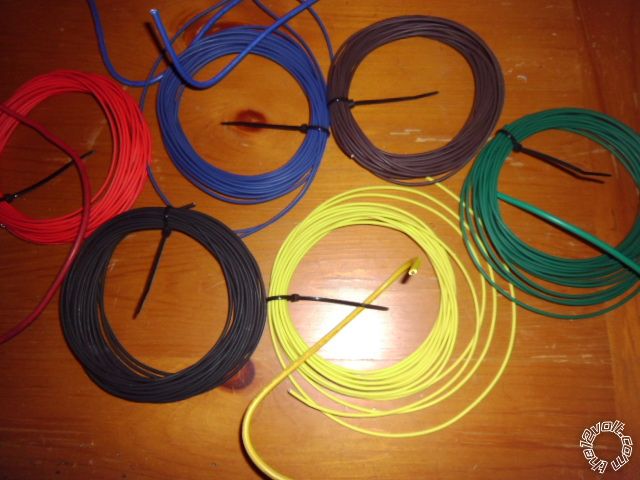
If you have a nice assortment of wire that is the same size or just slightly larger, in various colors, you could cut the thick R/S wires about 2" long and then solder on the matching color thin gauge wire, insulate with heat shrink tube and run that to the Tundra's ignition switch. ( Sorry for that run-on sentence.) Keeping it the same color makes everything easier. I do this on vehicles with the thin ignition wires using high guality18 gauge wire shown below with the corresponding thick R/S wire.
You can combine all the Red +12V power wires into one thick wire and connect that to an appropriate vehicle +12V supply wire. ------------- Soldering is fun!
Posted By: pentavolvo
Date Posted: February 09, 2014 at 7:04 PM
I basically do the same as kreg and it works great
Posted By: dustintinsley
Date Posted: February 11, 2014 at 5:29 PM
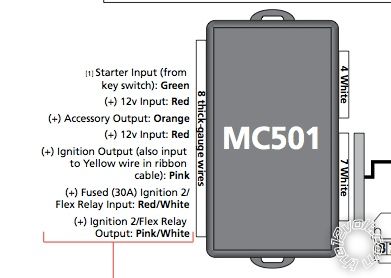
I am about to install a XpressStart One into a 2014 Tundra. I have a questions about one thing of the install. The highlighted comment in the diagram below. Connection 7 is the ribbon cable 9 (I believe). So, am I suppose to run a jumper from the pink wire to the yellow wire in that harness? That is what I am taking from that comment, just want to be sure. Seems kind of weird to do but that is what I am thinking I need to....
Posted By: dustintinsley
Date Posted: February 11, 2014 at 5:30 PM

This is on a 2014 Toyota Tundra....
Posted By: dasbogie
Date Posted: February 12, 2014 at 2:45 AM
no jumper needed
-------------
Advanced
Posted By: dustintinsley
Date Posted: February 12, 2014 at 7:44 AM
so i don't need to do anything with the yellow wire in the ribbon cable?
Posted By: dustintinsley
Date Posted: February 12, 2014 at 2:34 PM
I finally got the XpressStart One installed on my 2014 Toyota Tundra. Got everything installed and remotes paired. When I hit the unlock button, it does indeed unlock. Same for the lock, it works as it should. When I hit the start button, it acts as if I have turned the key to the ON position but it does not start. The gauges come one and it cycles a few times but never cranks. I am guessing I have something wrong with my wiring at the ignition. Here is the diagrams I used:
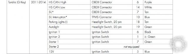
My current setup at the ignition is as follows:
Green wire hooked up to Starter 1 (green wire # 7) at ignition switch
Red wire hooked up to +12v constant
Orange wire (accessory output) is not hooked up to anything
Red wire hooked up to +12v constant
Pink wire hooked up to Ignition 1 (black wire # 6) at ignition switch
RED / White wire hooked up to Ignition 2 (Lt. Green wire #1) at ignition switch
Pink/White wire not hooked up
I am sure those are incorrect. Can anyone please give me guidance on correct connections
Posted By: kreg357
Date Posted: February 12, 2014 at 6:37 PM
A couple corrections :
Green wire hooked up to Starter 1 (green wire # 7) at ignition switch
Red wire hooked up to +12v constant
Orange wire (accessory output) hooked up to Gray wire @ Pin 2
Red wire hooked up to +12v constant
Pink wire hooked up to Ignition 1 (black wire # 6) at ignition switch
RED / White wire hooked up to +12V constant
Pink/White wire hooked up to (Lt. Green wire #1) at ignition switch *** Set for IGN2
-------------
Soldering is fun!
Posted By: dustintinsley
Date Posted: February 12, 2014 at 7:37 PM
how do i set pink/white wire fir IGN2?
Posted By: kreg357
Date Posted: February 12, 2014 at 8:51 PM
Not sure. I don't have an install guide for that system. It says Flex relay so it should be programmable. The default is usually IGN2.
-------------
Soldering is fun!
Posted By: dustintinsley
Date Posted: February 12, 2014 at 10:02 PM
thanks for all the help. the above corrections worked. all is working now
|