rf remote lock/unlock universal
Printed From: the12volt.com
Forum Name: Car Security and Convenience
Forum Discription: Car Alarms, Keyless Entries, Remote Starters, Immobilizer Bypasses, Sensors, Door Locks, Window Modules, Heated Mirrors, Heated Seats, etc.
URL: https://www.the12volt.com/installbay/forum_posts.asp?tid=136158
Printed Date: March 20, 2026 at 5:50 PM
Topic: rf remote lock/unlock universal
Posted By: axel87
Subject: rf remote lock/unlock universal
Date Posted: February 26, 2014 at 6:26 AM
Installed remote lock actuators in my truck recently, all is working great.
Then I thought why not throw in an RF kit for remote locks.
I installed the actuators with this relay schematic below-
https://www.the12volt.com/relays/relaydiagram49.html
I then connected the RF kit to the motor leg outputs.
Heres the kit I installed-
https://www./itm/370812147602?var=640085943999&ssPageName=STRK:MEWNX:IT&_trksid=p3984.m1439.l2649
I can hear the relays clicking in the module, but they will not activate the actuators.
My question is, is my choice of a relay diagram correct/compatible with this units operation?
I notice the unit has a one leg operation for lock unlock, were as my switch has 2 legs.
Thanks guys!
Replies:
Posted By: axel87
Date Posted: February 26, 2014 at 6:28 AM
I should add I ordered the 2 Channel self locking.
Added 12v power and gnd to unit, spliced into the two output legs of the switch relays.
Posted By: freqsounds
Date Posted: February 26, 2014 at 8:19 AM
Can you send the make/model of the RF kit? It messed up the URL.
Is the output on the RF kit a (-) output? Most of them are. If so, you'll have to change the design of the relays a little bit.
-------------
No question is stupid or not worth asking. You were once a noob, right? :)
Posted By: axel87
Date Posted: February 26, 2014 at 4:54 PM
https://www./itm/370812147602?var=640085943999&ssPageName=STRK:MEWNX:IT&_trksid=p3984.m1439.l2649
Try that link- dunno what happened with my original post.
Its a no name model. A Cheap kit, but hopefully itll work.
Still working with supplier, if I need to I am open to purchasing other quality kits, if you have recommendations.
Thanks again!
Posted By: axel87
Date Posted: February 26, 2014 at 8:39 PM
Posted By: axel87
Date Posted: February 26, 2014 at 8:41 PM
well wth... I dont understand how this is not working.
Copy paste link. Why does this keep screwing with me?
If anyone has the patience to deal with this, I would appreciate it.
Ebay
Search
DC 12V RF Wireless Remote Control Switch Receiver+Transmitter 2 CH /4 CH
This is the kit.
Sorry I cant get link to work
Posted By: axel87
Date Posted: March 01, 2014 at 1:20 PM
Would this be the relay wiring that I will need to implement instead?
https://www.the12volt.com/relays/relaydiagram4.html
Thanks for any help guys!
Posted By: freqsounds
Date Posted: March 01, 2014 at 1:31 PM
Alright, I got the diagram open. What configuration are you using? Is it the 2CH receiver+remote (self-locking)?
-------------
No question is stupid or not worth asking. You were once a noob, right? :)
Posted By: axel87
Date Posted: March 01, 2014 at 6:28 PM
Thank you for your time!
Correct, 2 channel self locking
I have the actuators wiring to seperate relays with a switch under this configuration-
https://www.the12volt.com/relays/relaydiagram49.html
This part is working correctly. I thought I could just hook up the output of the module to the actuator legs.
No go though :(
Any ideas?
Thanks
Posted By: freqsounds
Date Posted: March 01, 2014 at 7:36 PM
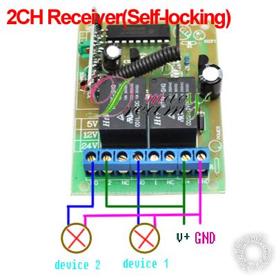
Starting from left to right, wire up as follows:
TERM1 - spliced into pin 86 from relay 1
TERM2 - +12V Constant
TERM3
TERM4 - spliced into pin 85 from relay 2
TERM5
TERM6
TERM7 - +12V Constant
TERM8 - Ground
The relays I'm speaking of are your existing relays that currently control the locks with a switch.
Now, if your locks operate backwards (i.e. unlock locks and lock unlocks) switch TERM1 and TERM4.
------------- No question is stupid or not worth asking. You were once a noob, right? :)
Posted By: axel87
Date Posted: March 01, 2014 at 11:49 PM
Will give that a try.
Going to be out of town for a few days, so I wont get back to this for a bit.
Question for you though while I am away-
Since I wired the module to terminal 30, why does this not work?
Shouldn't the module pass 12V through its relays to the actuators?
Thanks again!
Posted By: freqsounds
Date Posted: March 02, 2014 at 12:02 AM
Can you take a picture of your current setup and and label the wires? I might be able to answer that for you.
-------------
No question is stupid or not worth asking. You were once a noob, right? :)
|