relay behavior
Printed From: the12volt.com
Forum Name: Car Security and Convenience
Forum Discription: Car Alarms, Keyless Entries, Remote Starters, Immobilizer Bypasses, Sensors, Door Locks, Window Modules, Heated Mirrors, Heated Seats, etc.
URL: https://www.the12volt.com/installbay/forum_posts.asp?tid=136538
Printed Date: March 17, 2026 at 9:10 AM
Topic: relay behavior
Posted By: gargouille
Subject: relay behavior
Date Posted: April 28, 2014 at 7:12 PM
good day folks, here is the situation i need to resolve. i am using a relay to issue a + to a lighting system on my car. the relay is signaled by my alarm system issuing a -200MA ground. my issue. ive set the relay so that when triggered by a ground, it will output a + to the system. my problem is that there is a + feedback on the pin that is receiving the ground signal when the alarm system is sending the ground. ive tried to put a diode, but it will either block all signal or prevent the - to enter will keeping the + on the other side. what would be the way to fix this?
thank you
Eric ------------- Eric
Replies:
Posted By: howie ll
Date Posted: April 29, 2014 at 12:23 AM
Diode 1N4004 across the relay coil, 85 to 86 band to 86 (POS) side of the coil.
-------------
Amateurs assume, don't test and have problems; pros test first. I am not a free install service.
Read the installation manual, do a search here or online for your vehicle wiring before posting.
Posted By: gargouille
Date Posted: April 29, 2014 at 5:30 AM
diode installed on the wire that are coming out of the relay? ive tried with a 1n4001, didnt change a thing, is a 1n4004 "stronger"?
Eric
-------------
Eric
Posted By: howie ll
Date Posted: April 29, 2014 at 5:42 AM
Across the coil!
1N4004 handles the 200 volt "spike" when a relay shuts down.
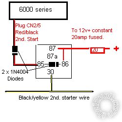
This is for something else but it illustrates what I mean, actually it's the you require:-
43Z_2nd._starter..bmp------------- Amateurs assume, don't test and have problems; pros test first. I am not a free install service.
Read the installation manual, do a search here or online for your vehicle wiring before posting.
Posted By: howie ll
Date Posted: April 29, 2014 at 5:45 AM
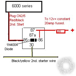
Just had another look at that picture and revised it:-
3EA_2nd._starter..bmp------------- Amateurs assume, don't test and have problems; pros test first. I am not a free install service.
Read the installation manual, do a search here or online for your vehicle wiring before posting.
Posted By: etellier911
Date Posted: April 29, 2014 at 9:15 AM
thank you i will try and hack a relay tonight to see how i can fit it in there...thx
Eric =)
Posted By: gargouille
Date Posted: April 29, 2014 at 5:47 PM
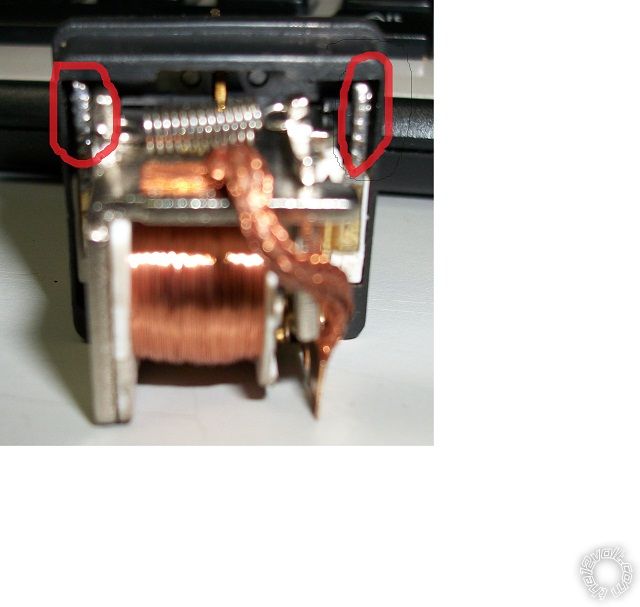
Good day, ive tried with a n4004 with one leg on each of these red spot that have solder on them and what seems to be the coil wire soldered on it. still no luck, with my test light, im still seeing a +12v signal on the input signal. ------------- Eric
Posted By: oldspark
Date Posted: April 29, 2014 at 8:29 PM
Much easier doing it external to the relay as described & shown in Howie's diagrams (line end to the more +ve 86, other end to the more -ve or GND 85).
Usually it's done as part of the wiring (in the base) to that relays can simply be replaced when needed.
Besides, I think the above relay pic shows its heavy terminals, not its coil terminals.
Posted By: howie ll
Date Posted: April 29, 2014 at 11:35 PM
You're right about the switch side not coil, that spring is the giveaway. Either solder diode across ON OUTSIDE or crimp in with the connectors.
-------------
Amateurs assume, don't test and have problems; pros test first. I am not a free install service.
Read the installation manual, do a search here or online for your vehicle wiring before posting.
Posted By: etellier911
Date Posted: May 02, 2014 at 11:25 AM
still no luck, tried to put a diode one leg on 85 and one on 86 same problem. will take a picture of the setup asap and post again.
thank you
Eric
Posted By: howie ll
Date Posted: May 02, 2014 at 11:33 AM
Don't waste 1 diode across coil + to 86 and - to 85, band to 86.
-------------
Amateurs assume, don't test and have problems; pros test first. I am not a free install service.
Read the installation manual, do a search here or online for your vehicle wiring before posting.
Posted By: oldspark
Date Posted: May 02, 2014 at 3:39 PM
I find the above ambiguous. I assume Howie means the (spike quenching) diode across the coil is not wasted. (IE - keep it even if it doesn't seem to help.)
That quenching diode across the coil will need to be an 1N4004 or 1N4007 to be safe. The voltage ratings of 1N4001-4003 are generally too low.
gargouille, when you say you have feedback, what problem is it causing?
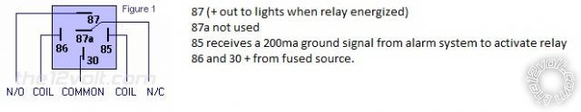
I presume you have #30 (else #87) to a +12V source; #87 (else #30) to your lights; #86 to the same or other +12V source, & #85 to the grounding alarm trigger?
Posted By: howie ll
Date Posted: May 02, 2014 at 4:55 PM
I meant theOP is wasting his time, terminal 85 if used as the coil NEG will always show a POS. It's simply current through the coil diode and never advise anything but 1N4004 because it's the most readily available and it's PIV is enough to quench the relay spike.
-------------
Amateurs assume, don't test and have problems; pros test first. I am not a free install service.
Read the installation manual, do a search here or online for your vehicle wiring before posting.
Posted By: oldspark
Date Posted: May 02, 2014 at 5:15 PM
My suspicion too, hence my what problem? question. IE - a voltage present on an open circuit is not feedback (it is a source....).
Posted By: howie ll
Date Posted: May 02, 2014 at 6:01 PM
Bloody iPad my last post should read current through the coil. The only 1amp diode I use and never advise anything but....
Sorry about that.
-------------
Amateurs assume, don't test and have problems; pros test first. I am not a free install service.
Read the installation manual, do a search here or online for your vehicle wiring before posting.
Posted By: gargouille
Date Posted: May 02, 2014 at 7:45 PM


hello again, as you can see on the picture, my test light gives me a positive feedback on the red wire that is connected to the wires that are sending the signal from the alarm CPU. the cpu sends a 200MA ground signal when activated. im using this as a remote activated light. my issue is that a +12 battery voltage is sent back to the cpu of the alarm . for clarity, the yellow wire is going to the device beeing lighted up, the purple and yellow/black are fused on +12v and the red receives the signal from the alarm cpu.
thank you once again for your time.
Eric ------------- Eric
Posted By: oldspark
Date Posted: May 02, 2014 at 8:36 PM
Yes - that is quite normal. Unless the ground side of the coil (85) is grounded, it will have the same voltage as its other side (86) - namely +12V.
That is not "feedback". It is simple circuit theory.
Just make sure your relay coil consumes less than 200mA (ie, a coil resistance higher than ~70 Ohms).
Posted By: davep.
Date Posted: May 03, 2014 at 1:50 AM
Hook up your test light exactly like you have it in the picture above. The test light will be on. This is normal, and correct, for the way you have the relay wired.
Activate your alarm trigger. The test light should go out while the trigger is being received. If it does, even just briefly, the circuit is working.
I'm wondering if you're receiving a 'pulse' trigger, which is very brief, and you're not getting the activation you expect?
Perhaps you are expecting what the industry calls a "validity trigger" which is where the (-) pulse is sent for as long as you hold the button down on the transmitter? If so, consult your installation manual for instructions on how to program this characteristic.
I don't understand what the "problem" your experiencing with your circuit is. The difference between a pulse and a validity trigger is all I have for now. If this isn't the problem, try to explain exactly what your circuit isn't doing "correctly". Because the way it's wired, and what your seeing with your test light is correct.
The anti-spike diode these guys are having you do has nothing to do with solving your issue.
Posted By: howie ll
Date Posted: May 03, 2014 at 1:58 AM
Davep you're quite correct. I believe our OP has tested before trying, nothing wrong with that but lack of subject knowledge has given us the original question.
And yes Davep I know you and I are opposite sides of the "to diode or not question"  ------------- Amateurs assume, don't test and have problems; pros test first. I am not a free install service.
Read the installation manual, do a search here or online for your vehicle wiring before posting.
Posted By: oldspark
Date Posted: May 03, 2014 at 2:54 AM
I was thinking of high-resistance paths etc until Howie mentioned the spike issue. IMO that was brilliant - I have often seen problems caused by spikes whether thru the power distribution or inductive etc coupling across circuits.
It should be obvious that because the OP mentioned "feedback", I assumed it was a feedback problem. It wasn't until later that I got suspicious.
As to " 2D or not 2D?" (2 diode or not 2 diode), I have certainly read & heard of many non-dioded disasters (and I have heard a few non-dioded kicks!) but I can't recall ever having issues.
I am surprised however that some product instruct the use of diode protection "if" relays are to be driven. (IMO in that case they should be included in the product - especially when very few would drive anything other than relays!  )
Posted By: howie ll
Date Posted: May 03, 2014 at 3:00 AM
And if anyone wants to know anything about radiated and inductive interference, let me take you back one day to suppressing (or trying t) deal with) a 70s Lotus Europa or nearly any Renault or Fiat in those days, even down to bonding the exhaust!
There's a classic post by Mr. Idiot about finding out about the spike in a painful way.
-------------
Amateurs assume, don't test and have problems; pros test first. I am not a free install service.
Read the installation manual, do a search here or online for your vehicle wiring before posting.
Posted By: gargouille
Date Posted: May 03, 2014 at 5:27 AM
Hello Folks, the alarm does what it is supposed to do when i push the button, im just worried about the + signal sent back to the cpu of the alarm. that is why i wanted to get rid of that +. i just wanted to be precautious about not frying the cpu. and for the signal sent, one is latch, one is 90 sec timed.
Eric
so, no way to prevent that + effect on the relay? and no danger to cpu?
-------------
Eric
Posted By: howie ll
Date Posted: May 03, 2014 at 5:43 AM
Not if you diode it as shown. Having said that there are two schools of thought, one says modern units are protected internally but I won't take the chance. Done it myself and seen it happen on this site.
-------------
Amateurs assume, don't test and have problems; pros test first. I am not a free install service.
Read the installation manual, do a search here or online for your vehicle wiring before posting.
Posted By: oldspark
Date Posted: May 03, 2014 at 12:36 PM
gargouille - if the alarm output is intended for a relay, it should have its own internal protection - namely a reverse biased diode from that output to its +5V or +12V supply.
As to the +12V on the relay coil, it is +12V because its other end is connected to +12V and no current is flowing.
When you ground that "switched" end, it becomes 0V (GND) and will have a current i flowing thru it's coil resistance R where iR = V = 12V (Ohm's Law), or R=V/i = 12/.2A for 200mA => R = 60A or higher for a current of 200mA or less to flow if 12V. Hence my comment earlier about a relay coil of at east ~70 Ohms or rated for under 200mA at 12V or 13V etc.
Most circuits function that way. A voltmeter will read whatever voltage an open connection is connected to.
An ammeter will act as a short (closed switch) and measure the current (eg, thru the coil).
|