aftermarket backup sensor so loud
Printed From: the12volt.com
Forum Name: Car Security and Convenience
Forum Discription: Car Alarms, Keyless Entries, Remote Starters, Immobilizer Bypasses, Sensors, Door Locks, Window Modules, Heated Mirrors, Heated Seats, etc.
URL: https://www.the12volt.com/installbay/forum_posts.asp?tid=136741
Printed Date: April 03, 2026 at 2:19 AM
Topic: aftermarket backup sensor so loud
Posted By: cpgoose
Subject: aftermarket backup sensor so loud
Date Posted: June 02, 2014 at 9:37 PM
Hi folks,
So I bought this backup sensor from Amazon and installed it on my car.
here's the link
The problem is that it's so LOUD! Instead of wiring it to the backup lights, I just installed it to an on/off switch so I can use it when I want. If you look at the pictures, the last picture is of the LED display. That is where the little speaker resides that beeps. I opened it up to see what it looks like, and the little speaker is soldered to the circuit board.
Any ideas on how to control the volume of the speaker? Potentiometer? Rheostat? Please don't say to just put a piece of tape over it :-) I actually did that, and it's still loud.
Any ideas would be great?
Replies:
Posted By: oldspark
Date Posted: June 02, 2014 at 9:49 PM
I usually put tape over the buzzer/speaker hole/grille.
Posted By: i am an idiot
Date Posted: June 03, 2014 at 8:15 AM
Start with scotch tape, then if that does not deaden it enough try a couple layers of electrical tape. And then there is always Duct Tape.
Posted By: cpgoose
Date Posted: June 03, 2014 at 11:29 AM
Thanks for the replies.
I guess I was looking more to "control" the volume rather than just muffle it. I was hoping someone was going to say I could unsolder the speaker from the board, solder in a wire with the speaker attached, and then put in a rheostat/potentiometer to control the volume.
Posted By: the12volt
Date Posted: June 03, 2014 at 11:53 AM
cpgoose, yes, you can do it as you described with an L-Pad. Your local Radio Shack will likely have what you need for under $5.00. -------------  the12volt Support the12volt.com the12volt Support the12volt.com
Posted By: cpgoose
Date Posted: June 03, 2014 at 12:53 PM
Thanks so much! If you don't mind, two more follow-up questions - I'm very new to this portion of electronics.
1) Do I need to know the ohms and wattage of the speaker on the circuit board in order to pick out the L-pad, or does it not matter since it's a tiny speaker?
2) Also, once I remove the speaker from the circuit board, any tips on the next step? Can I solder actual wire to hang off the board?
Thanks so much!
Posted By: cpgoose
Date Posted: June 05, 2014 at 3:07 PM
I scanned the board so you could see. The 2nd and 3rd images are the same, I just labeled the 3rd one.
You can see the tiny speaker in the first image. In the 3rd image I labeled what I think are the two terminals for the speaker. What's strange (to me at least) is that it looks like the board's inner wiring only goes to one of the speaker terminals and not both. 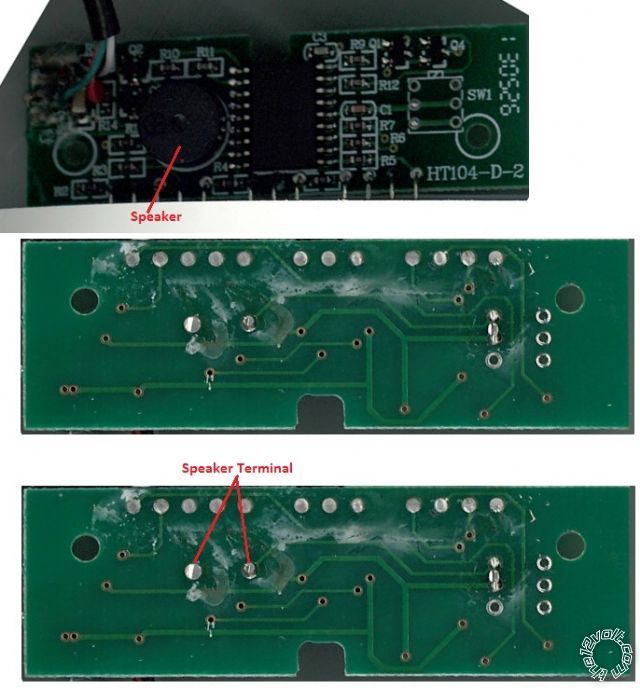
Posted By: i am an idiot
Date Posted: June 05, 2014 at 8:06 PM
There is a trace under the buzzer. One terminal is fed from the bottom of the board. The other is fed from the top side.
Before you go and try to reinvent the wheel, a layer or 2 of scotch tape will work wonders.
Posted By: cpgoose
Date Posted: June 09, 2014 at 12:29 PM
One last follow-up question: The wires for each of the 4 sensors are a little too short. I cut the connector off one of them and there are two wires inside with silver shielding. Any tips on how to extend these wires without losing the shielding capability? I've never extended shielded wire before.
Posted By: howie ll
Date Posted: June 09, 2014 at 2:10 PM
Mr. I Aka how to ruin a perfectly good back-up device.
Alternatives to tapes..
Relocate behind the panel
Put a sock in it, over it etc.
OP next time you're reversing in a strange place with the music at a high volume and you hear a crashing sound please ask your self why you wanted to make it quieter. 
As Mr. I said this site is full of people trying to re-invent the wheel who also don't look at the archives.
And aren't you skinny now Mr. I. ------------- Amateurs assume, don't test and have problems; pros test first. I am not a free install service.
Read the installation manual, do a search here or online for your vehicle wiring before posting.
Posted By: cpgoose
Date Posted: June 10, 2014 at 9:00 AM
Ok, the point was to control the volume so if I'm arriving somewhere and the kids are asleep, I could put the volume very low or even off and still be able to use the LEDs on the backup display for assistance in backing up. A loud/obnoxious beeping sound would definitely wake them up, making for cranky kids and wife. SO, hiding it behind a panel kind of defeats the purpose. Plus, isn't reinventing the wheel the whole point to boards like this? Who wants to re-use the same wheel!
Posted By: howie ll
Date Posted: June 10, 2014 at 2:46 PM
Why not just run an on/off switch to the front of the vehicle.
-------------
Amateurs assume, don't test and have problems; pros test first. I am not a free install service.
Read the installation manual, do a search here or online for your vehicle wiring before posting.
Posted By: cpgoose
Date Posted: June 10, 2014 at 2:52 PM
Yep, did that. You can't use the LED portion when you shut off the whole system, though.
Posted By: howie ll
Date Posted: June 10, 2014 at 2:54 PM
I meant for the speaker only.
-------------
Amateurs assume, don't test and have problems; pros test first. I am not a free install service.
Read the installation manual, do a search here or online for your vehicle wiring before posting.
Posted By: cpgoose
Date Posted: June 10, 2014 at 3:30 PM
Yea, that's an option - you're kind of going back to the beginning replies of this topic. Some people didn't seem to think it would be a good idea to desolder the exising speaker because it might screw something up in the board. That's what I was asking, though, whether I could take the speaker out and either put in a switch or an L-pad.
Posted By: howie ll
Date Posted: June 10, 2014 at 4:32 PM
Just cut one of the tracks and run to an on/off switch.
-------------
Amateurs assume, don't test and have problems; pros test first. I am not a free install service.
Read the installation manual, do a search here or online for your vehicle wiring before posting.
Posted By: oldspark
Date Posted: June 10, 2014 at 8:31 PM
Interestingly one track from the speaker goes to the unused switch. Maybe that could help your mod - ie, cut that pin's track on the other side of the PCB &/or insert pot or switch wires there.
I was also thinking that being (possibly) a piezo buzzer its impedance may be hard to determine, or a pot/resistor may effect its operation.
But it seems similar buzzers are also describes as electromagnetic types which typically have impedances from 16 to 80 Ohms, tho some may be higher (eg, 200 Ohms).
I'd try a smallish resistor (10 to 100 Ohms) to see its effect and then guess what pot might suit (ie, 20, 100, 200 Ohm etc).
I was also thinking a resistor or pot plus series resistor (to prevent a zero Ohm short) could be placed in parallel with the buzzer/speaker, but without knowing the driving circuit, that could be destructive to that circuit.
Posted By: i am an idiot
Date Posted: June 10, 2014 at 8:57 PM
You will not damage the board if you use these simple board saving techniques. Put a little extra solder on both of the connections. Let it cool back down completely. Heat one of the connections till the solder is molten, gently lift that side of the driver till you feel it move. Do not try to remove that pin, we have to walk it out of the holes. Let it cool then heat the other connection till molten, then lift that side of the driver, it should move about twice as far as the first side moved. Let it cool and go to the other connection. Repeat till it is removed. If you have a solder sucker, now is the time you want to use it.
Posted By: oldspark
Date Posted: June 10, 2014 at 9:20 PM
Yeah, solder suckers are great - especially when removing 64 pin leaded (QUIP) chips etc! Mind you, Mr I's walking technique is still often required...
But for 2-pin devices I often don't bother with a sucker. Instead I heat one pin at a time whilst gently but firmly persuading that pin up/out a bit, then do the other, then back to the first. (And often burning finger tips in the process LOL!)
The more it works out, the bigger each pull thru or walking step can be.
Of course I am merely repeating Mr I's technique above... for what it's worth.
If I can melt the full hole then I won't ad the initial solder, but sometimes adding solder is needed to melt the rest - tho I usually won't allow that first cool down except where needed (ie, it's already too hot). [Funny how that reminds me of dripping water into my ear so I can get existing trapped water out!]
After a while you get quite good at it and get a good feel for what PCBs & tracks can tolerate - or more importantly - how many times they will tolerate it. But I have had self-destructo's - usually repeat work where it doesn't matter how careful you are, tracks simply lift or destruct. Then you replace each track manually with wire - and that's not fun for 0.5mm spaced SMD chips!
|