Viper 5706v, 2010 Hyundai Elantra
Printed From: the12volt.com
Forum Name: Car Security and Convenience
Forum Discription: Car Alarms, Keyless Entries, Remote Starters, Immobilizer Bypasses, Sensors, Door Locks, Window Modules, Heated Mirrors, Heated Seats, etc.
URL: https://www.the12volt.com/installbay/forum_posts.asp?tid=137012
Printed Date: March 09, 2026 at 8:36 PM
Topic: Viper 5706v, 2010 Hyundai Elantra
Posted By: wissam1981
Subject: Viper 5706v, 2010 Hyundai Elantra
Date Posted: July 27, 2014 at 7:43 PM
Hello,
I want to install a Viper 5706v alarm on my Hyundai Elantra 2010,
I have purchased the following items:
1. Viper 5704v Full Feature Car Alarm with Remote Start and 2-way Pager
2. DBALL2Pro
3. Directed Electronics Inc XKLOADER2 XpressKit
I have already flashed the DBALL2Pro for Hyundai Elantra 2010(I have checked all available options in Standard install configuration) but I have difficulties in understanding how to wire the Viper 5707v with DBALL2Pro and with my car, i will attach the 3 devices wiring diagrams
I would be grateful if someone can help me to figure out the right installation ( step by step)
thank you in advance.
Replies:
Posted By: catback
Date Posted: July 27, 2014 at 8:39 PM
wissam1981 wrote:
I have difficulties in understanding how to wire the Viper 5707v with DBALL2Pro and with my car
Ax the DBALL2Pro and pick up a DBALL2, things will appear clearer then (with the install guides and interconnecting).
Posted By: wissam1981
Date Posted: July 28, 2014 at 4:56 PM
what you mean, can you explain more, and if you can show me how to connect the wires
thanks for your reply
Posted By: howie ll
Date Posted: July 28, 2014 at 5:21 PM
DB-ALL PRO is the wrong unit for that alarm and your vehicle it should be a DB-ALL2.
-------------
Amateurs assume, don't test and have problems; pros test first. I am not a free install service.
Read the installation manual, do a search here or online for your vehicle wiring before posting.
Posted By: catback
Date Posted: July 29, 2014 at 2:20 AM
What he ^ said...The DBALL2Pro is a all in one type unit it doesn't interface with the 5704v where-as the DBALL2 does. If you want to keep the DBALL2Pro then you need to get a MC501 and ax the 5704v.
Posted By: howie ll
Date Posted: July 29, 2014 at 4:05 AM
Go to Xpresskit, look up your car type 2 I believe only about 5 wires to DB-ALL 2 plus a few from the 5704.
-------------
Amateurs assume, don't test and have problems; pros test first. I am not a free install service.
Read the installation manual, do a search here or online for your vehicle wiring before posting.
Posted By: wissam1981
Date Posted: July 29, 2014 at 7:55 AM
catback wrote:
What he ^ said...The DBALL2Pro is a all in one type unit it doesn't interface with the 5704v where-as the DBALL2 does. If you want to keep the DBALL2Pro then you need to get a MC501 and ax the 5704v.
thanks for your reply,
I have some questions,
1- i will return the DBALL2Pro cause i can't find and purchase the (MC501) online
2- i will purchase the DBALL2 depending on your advise ( https://www.amazon.com/Directed-Electronics-Inc-DBALL2-Channels/dp/B00H2PHSY2/ref=sr_1_1?ie=UTF8&qid=1406637447&sr=8-1&keywords=DBALL2 )
3- should i keep the ( Directed Electronics Inc XKLOADER2 XpressKit ) ? for flashing the DBALL2 or No need it any more ?
4- any another advise or cables i will need it for this installation?
5- can any one provide the Viper 5704v Wiring Diagram ?
thanks in advance.
Posted By: howie ll
Date Posted: July 29, 2014 at 9:29 AM
2) Yes.
3) No if the vendor flashes it for you.
4) From your questions, have it installed professionally.
5) Should be on this site, Downloads/Manuals section or the re3ady reference sheet.
5204 5704 5904/6 are all the same.
-------------
Amateurs assume, don't test and have problems; pros test first. I am not a free install service.
Read the installation manual, do a search here or online for your vehicle wiring before posting.
Posted By: wissam1981
Date Posted: July 30, 2014 at 12:32 PM
howie ll wrote:
2) Yes.
3) No if the vendor flashes it for you.
4) From your questions, have it installed professionally.
5) Should be on this site, Downloads/Manuals section or the re3ady reference sheet.
5204 5704 5904/6 are all the same.
Hello,
i appreciate your help, i have last request i hope you can help with
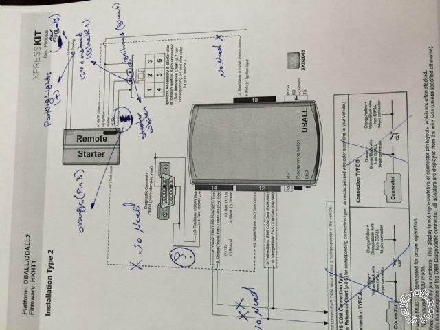
i need to show me how to wiring according to the diagrams below
Hyundai Elantra

DBALL2 Type 2 Diagram

Viper 5706v

Posted By: wissam1981
Date Posted: July 30, 2014 at 12:35 PM
howie ll wrote:
2) Yes.
3) No if the vendor flashes it for you.
4) From your questions, have it installed professionally.
5) Should be on this site, Downloads/Manuals section or the re3ady reference sheet.
5204 5704 5904/6 are all the same.
Please if you can in details( step by step)
thank you
Posted By: howie ll
Date Posted: July 30, 2014 at 2:07 PM
Actually no I can't the diagram above shows the wrong set up no mention of 5704 or 5606, you mentioned booth in your first post.
Secondly you aren't listening to anything Catback or I told you about compatibility.
Third I've no intention of even starting to explain every last connection.
You have to start somewhere, get the right equipment look up your vehicle here in the Vehicle Wiring Section.
To be honest from the way you're phrasing your questions, I must re-iterate that you take this to a professional.
-------------
Amateurs assume, don't test and have problems; pros test first. I am not a free install service.
Read the installation manual, do a search here or online for your vehicle wiring before posting.
Posted By: catback
Date Posted: July 31, 2014 at 10:43 AM
X 2 on Howie's comment. I can't stress enough know what your connecting and know what your connecting it with. If you have no idea on this stuff at the very least soak in ALOT of youtube and internet concerning this stuff. ANYONE that decides undertake an install of this caliber should know a great deal about the unit they installed and the vehicle they installed it in by the time they are finished. More than just what wires connect to where, but things like purpose and function. The more you know before even starting your own installation the better. The internet is great for learning new things so again soak it up.
I'll reiterate what howie said, that diagram for the DBALL2Pro is nothing like the proper diagram for the DBALL2.
Posted By: wissam1981
Date Posted: August 03, 2014 at 5:23 PM
howie ll wrote:
Secondly you aren't listening to anything Catback or I told you about compatibility.
.
Hello,
first, thank you for your replies, i appreciate it
second, what you mean about the compatibility, do you mean that these devices not compatible with my Vehicle?
Regards,
Posted By: catback
Date Posted: August 03, 2014 at 6:32 PM
The DBALL2Pro is not designed to connect to a 5706v or like unit. The DBALL2Pro is a standalone unit.
A DBALL2 will connect to a 5706v, a DBALL2Pro will NOT! That is the compatibility issue.
Posted By: howie ll
Date Posted: August 04, 2014 at 2:38 AM
Which is what we've told you about 3 times now hence the comment about not listening.
-------------
Amateurs assume, don't test and have problems; pros test first. I am not a free install service.
Read the installation manual, do a search here or online for your vehicle wiring before posting.
Posted By: wissam1981
Date Posted: August 04, 2014 at 9:16 AM
howie ll wrote:
DB-ALL PRO is the wrong unit for that alarm and your vehicle it should be a DB-ALL2.
yes, i follow your advice and replaced the DBALL2Pro with DBALL2, and i told you in previous post that i did that!
Posted By: catback
Date Posted: August 04, 2014 at 9:47 AM
wissam1981 wrote:
howie ll wrote:
DB-ALL PRO is the wrong unit for that alarm and your vehicle it should be a DB-ALL2.
yes, i follow your advice and replaced the DBALL2Pro with DBALL2, and i told you in previous post that i did that!
Ok then you use the install guide for the DBALL2 and not the DBALL2Pro which you have displayed in your diagram post.
Posted By: howie ll
Date Posted: August 04, 2014 at 10:17 AM
Exactly then we can maybe help you.
-------------
Amateurs assume, don't test and have problems; pros test first. I am not a free install service.
Read the installation manual, do a search here or online for your vehicle wiring before posting.
Posted By: wissam1981
Date Posted: August 22, 2014 at 4:14 PM
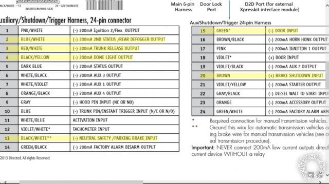
Hello guys,
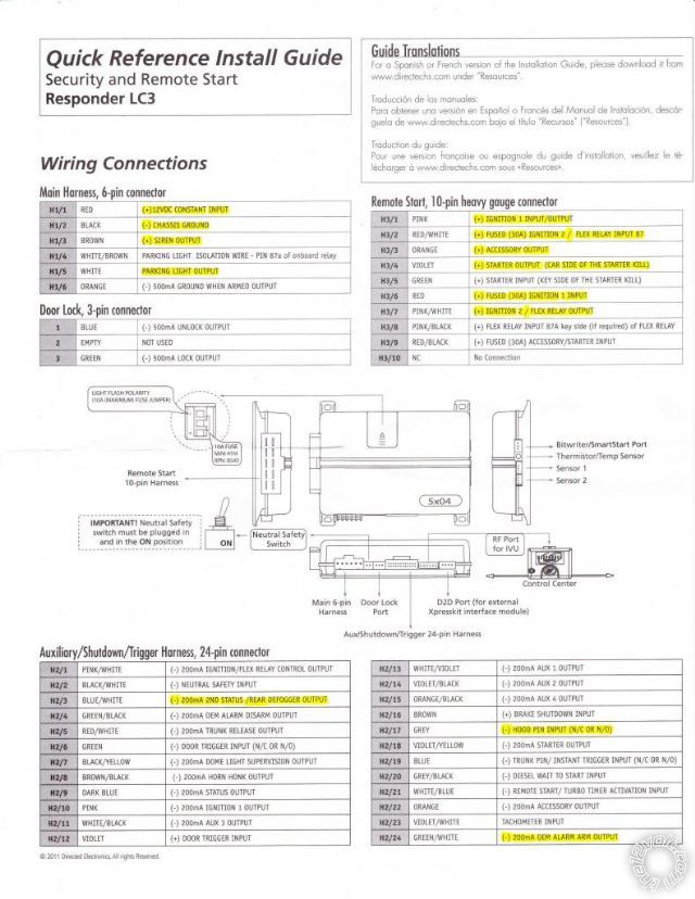
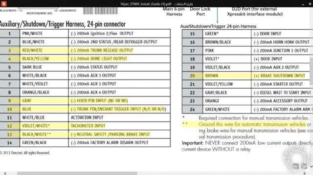
today i received my viper 5706v with DBall2, and from the viper guide i figure out that the wires that should hugged up is as in the image below with yellow highlights, please i need to make sure of this first step of this installation
Posted By: howie ll
Date Posted: August 22, 2014 at 5:38 PM
Quick and dirty answer because I can't read any of the above.
Just go to Xpresskit.com, punch in your year, make and model and follow their diagram, that simple.
-------------
Amateurs assume, don't test and have problems; pros test first. I am not a free install service.
Read the installation manual, do a search here or online for your vehicle wiring before posting.
Posted By: catback
Date Posted: August 23, 2014 at 10:55 AM
You'll need more than that, the DBALL2 only does transponder bypass and tach on the 2010 elantra.
You need
Door locks, blue and green
H3/5 on the RS Harness if you want starter kill/anti-grind
H3/9 if you expect the remote starter to actually engage the starter
H2/2 again if you expect the remote starter to work
H2/5 if you want to pop your trunk with the remote (optional)
H2/6 for the alarm to work and to be able to program the alarm
H2/7 optional for dome light supervision
H2/16 required for proper remote start take-over function and anti-theft
If you aren't hooking up the DBALL2 in D2D mode but instead use W2W then H2/9 and H2/23 are required for remote start to work. Again not necessary in D2D mode.
Posted By: wissam1981
Date Posted: August 24, 2014 at 8:55 AM
catback wrote:
You'll need more than that, the DBALL2 only does transponder bypass and tach on the 2010 elantra.
You need
Door locks, blue and green
H3/5 on the RS Harness if you want starter kill/anti-grind
H3/9 if you expect the remote starter to actually engage the starter
H2/2 again if you expect the remote starter to work
H2/5 if you want to pop your trunk with the remote (optional)
H2/6 for the alarm to work and to be able to program the alarm
H2/7 optional for dome light supervision
H2/16 required for proper remote start take-over function and anti-theft
If you aren't hooking up the DBALL2 in D2D mode but instead use W2W then H2/9 and H2/23 are required for remote start to work. Again not necessary in D2D mode.
Hello,
I went today to a pro. man, he checked my car and find out that the there is NO security in the car and try to start the car without the key in the ignition (the car started ).
He told me that the viper don't need a DBall2 to work, (just the viper ) is that right??????
also he ask me some questions about the Viper Diagram ( Some symbols ) and i couldn't answer him, the first question regarding the Central Control Lock
my Question is as follow
1- is it right that the DBall2 doesn't required for this installation because there is no security in my car
2- i don't have the knowledge to understand the difference between the W2W and D2D, and which should i use, and what the benefits of it?
2- i need to figure out how to find the Central Contral Lock in viper diagram
Regards,
Posted By: howie ll
Date Posted: August 24, 2014 at 9:09 AM
There is no figuring out, you can do it without the DB-All but there's a lot more wiring involved.
The easiest method is DB-ALL wired D2D.
I strongly advise you NOT to do this yourself, your knowledge (I don't know your strip, test and solder abilities) seems woefully inadequate.
But don't go to that pro any one with ANY experience would know that with few exceptions every Japanese/Korean vehicle uses NEG trigger locks therefore the lock/unlock plug and wires on the Viper would be fine.
Provided you're able to strip, test and confirm and solder plus you aren't colour blind go the DB-ALL2 + D2D route it will save tears and lots of daft questions.
-------------
Amateurs assume, don't test and have problems; pros test first. I am not a free install service.
Read the installation manual, do a search here or online for your vehicle wiring before posting.
Posted By: howie ll
Date Posted: August 24, 2014 at 9:10 AM
I should explain better, The DB-ALL2 and security are one thing, the other thing it does is save you literally hours of wiring.
-------------
Amateurs assume, don't test and have problems; pros test first. I am not a free install service.
Read the installation manual, do a search here or online for your vehicle wiring before posting.
Posted By: howie ll
Date Posted: August 24, 2014 at 10:22 AM
6 connections to be made, possibly an all time record.
Go to Xpresskit, look up your vehicle, type 2 diagram, blimey talk about easy.
-------------
Amateurs assume, don't test and have problems; pros test first. I am not a free install service.
Read the installation manual, do a search here or online for your vehicle wiring before posting.
Posted By: wissam1981
Date Posted: August 24, 2014 at 10:26 AM
So now i have to start from the scratch, cause no one in my area that install viper
i have to do it ( with your help ) to figure out what wires should i hugged up
so what the first step?
Posted By: howie ll
Date Posted: August 24, 2014 at 10:31 AM
This:-
Go to Xpresskit, look up your vehicle, type 2 diagram.
-------------
Amateurs assume, don't test and have problems; pros test first. I am not a free install service.
Read the installation manual, do a search here or online for your vehicle wiring before posting.
Posted By: howie ll
Date Posted: August 24, 2014 at 10:36 AM
Where are you in Florida?
-------------
Amateurs assume, don't test and have problems; pros test first. I am not a free install service.
Read the installation manual, do a search here or online for your vehicle wiring before posting.
Posted By: wissam1981
Date Posted: August 24, 2014 at 10:37 AM
No, outside USA
Posted By: howie ll
Date Posted: August 24, 2014 at 10:45 AM
That's what I thought from your English so where?
Can't be Europe, it would have an immobiliser.
-------------
Amateurs assume, don't test and have problems; pros test first. I am not a free install service.
Read the installation manual, do a search here or online for your vehicle wiring before posting.
Posted By: catback
Date Posted: August 24, 2014 at 10:45 AM
Howie, I'm glad you work on 12v electronics and not computers. That last link is utterly useless to us out on the internets.
If you can do without the dball2 and can do something else with it then I'd say do it (leave it out).
On this model year (2010) elantra the dball2 only does transponder bypass and tach output so if your car doesn't have a transponder key then the only thing the dball2 would be doing is tach output.
What does this professional normally do work wise? The part of the viper diagram that covers door locks is expressly to the point and simple. It doesn't have a 5 wire/central locking internal relay setup, if he needs that stuff then a 451m module is what he needs to go with the viper.
Posted By: wissam1981
Date Posted: August 24, 2014 at 10:46 AM
howie ll wrote:
This:-
Go to Xpresskit, look up your vehicle, type 2 diagram.
Okay, I have it, i need to Know some symbols
1- i don't know what (-) GWR (Status) stand for and where to connect it to Viper ( to which wire or harness ) ??????
2- 5: Violet/White: (AC) Tach Output ( same as above ) where connect to ????
Posted By: howie ll
Date Posted: August 24, 2014 at 10:50 AM
Whoah Catback, Oriental vehicle needing anything but NEG lock triggers?
Only early UK spec Lexus IS and some Mits models not sold in the US.
The point I was making was that it was far easier to do it with DB-ALL2.
I did a 2010 Yaris on Friday, UK version needs a hood switch and tach is pin 9 on the OBD ll I bought a 556U AND a DB-ALL2 with me, easier to hard wire.
-------------
Amateurs assume, don't test and have problems; pros test first. I am not a free install service.
Read the installation manual, do a search here or online for your vehicle wiring before posting.
Posted By: catback
Date Posted: August 24, 2014 at 11:02 AM
Howie, I'm not saying how to do it or what needs to be done. Just addressing what the "Pro" might be looking for. Some alarms/keyless units have a built-in 451m type "central lock" deal so if the guy is expecting to see that well he won't unless he gets a 451m.
(-) GWR (Status) = Ground While Running status that is active when the wire is connected to ground (-)...This is how the remote start tells the bypass that a remote start session is taking place, the remote start unit grounds this wire during a remote start.
(AC) Tach Output = Tachometer/RPM output from the dball2 to the remote start. The dball2 reads the tach/rpm through the vehicle's CAN/Data system and generates an AC signal to send to the remote start unit. The remote start unit uses a tach signal to determine when the car has started and if the car is running.
Posted By: wissam1981
Date Posted: August 24, 2014 at 11:02 AM
BTW, my car doesn't have OBD2 too
Posted By: howie ll
Date Posted: August 24, 2014 at 11:04 AM
Oh yes I does where are you. Every vehicle in the world has either an OBD 1 from c.1998 or OBD ll from 2008.
And there are other places to pick up those CAN Hi and Lo wires, BCM, driver door loom etc.
-------------
Amateurs assume, don't test and have problems; pros test first. I am not a free install service.
Read the installation manual, do a search here or online for your vehicle wiring before posting.
Posted By: wissam1981
Date Posted: August 24, 2014 at 11:09 AM
catback wrote:
(-) GWR (Status) = Ground While Running status that is active when the wire is connected to ground (-)...This is how the remote start tells the bypass that a remote start session is taking place, the remote start unit grounds this wire during a remote start.
(AC) Tach Output = Tachometer/RPM output from the dball2 to the remote start. The dball2 reads the tach/rpm through the vehicle's CAN/Data system and generates an AC signal to send to the remote start unit. The remote start unit uses a tach signal to determine when the car has started and if the car is running.
this is good information, but where should be hugged up with viper ????
Posted By: howie ll
Date Posted: August 24, 2014 at 11:13 AM
Not needed if you use the DB-ALL2, in D2D mode, that's why the diagram shows dotted lines.
Again where are you, why should I answer your questions when you don't acknowledge mine?
-------------
Amateurs assume, don't test and have problems; pros test first. I am not a free install service.
Read the installation manual, do a search here or online for your vehicle wiring before posting.
Posted By: wissam1981
Date Posted: August 24, 2014 at 11:18 AM
howie ll wrote:
Again where are you, why should I answer your questions when you don't acknowledge mine?
i am sorry about that, i am in Middle East
Posted By: howie ll
Date Posted: August 24, 2014 at 11:30 AM
Where?
-------------
Amateurs assume, don't test and have problems; pros test first. I am not a free install service.
Read the installation manual, do a search here or online for your vehicle wiring before posting.
Posted By: wissam1981
Date Posted: August 24, 2014 at 11:38 AM
Iraq My Friend
Posted By: wissam1981
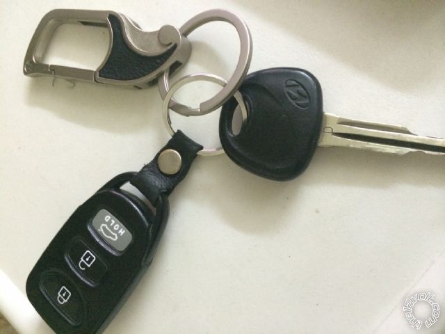
Date Posted: August 24, 2014 at 11:44 AM
howie ll wrote:
Not needed if you use the DB-ALL2, in D2D mode, that's why the diagram shows dotted lines.
This is what you meant by D2D ???? 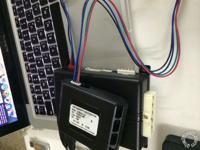
Posted By: howie ll
Date Posted: August 24, 2014 at 11:47 AM
Yes to the above photo and if only there were peace in the middle east you could drive to Israel where there are loads of qualified people to install it.
And I'm not being funny,I'm Jewish myself and I've helped Iraqis and Egyptians before, the more we all help each other the more chance of peace and prosperity.
-------------
Amateurs assume, don't test and have problems; pros test first. I am not a free install service.
Read the installation manual, do a search here or online for your vehicle wiring before posting.
Posted By: wissam1981
Date Posted: August 24, 2014 at 11:52 AM
howie ll wrote:
Yes to the above photo and if only there were peace in the middle east you could drive to Israel where there are loads of qualified people to install it.
And I'm not being funny,I'm Jewish myself and I've helped Iraqis and Egyptians before, the more we all help each other the more chance of peace and prosperity.
wow, these words are the best that i heard today, thank you for these words
Posted By: howie ll
Date Posted: August 24, 2014 at 11:58 AM
Nice one  ------------- Amateurs assume, don't test and have problems; pros test first. I am not a free install service.
Read the installation manual, do a search here or online for your vehicle wiring before posting.
Posted By: wissam1981
Date Posted: August 24, 2014 at 12:02 PM
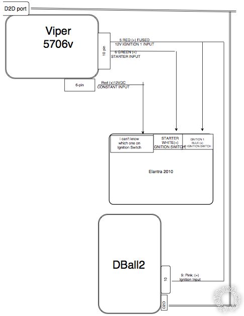
howie ll i am trying now to draw a diagram combine all three devices ( Elantra 2010, Viper 5706v, and DBall2 )
so please i will post it, and you can correct me
Posted By: howie ll
Date Posted: August 24, 2014 at 12:15 PM
OK but it might be tomorrow, it's 6:15 pm here and what 10:15 your time? I'm going to watch TV and make some dinner!
-------------
Amateurs assume, don't test and have problems; pros test first. I am not a free install service.
Read the installation manual, do a search here or online for your vehicle wiring before posting.
Posted By: wissam1981
Date Posted: August 24, 2014 at 1:24 PM
I draw this simple diagram ( according to knowledge ). correct me if i am wrong
i think this the first step on the road
if anyone can advice me to the next step ( i mean what anther wires should i hugged up )
BTW, sorry the bad english, this is my best
Posted By: wissam1981
Date Posted: August 24, 2014 at 1:30 PM
I draw this simple diagram ( according to knowledge ). correct me if i am wrong
i think this the first step on the road
if anyone can advice me to the next step ( i mean what anther wires should i hugged up )
BTW, sorry the bad english, this is my best.
Posted By: catback
Date Posted: August 24, 2014 at 7:29 PM
I thought we covered this pages ago? You highlighted some and I listed everything else you WILL be using. If your "Pro" is right about the elantra having no factory security and being able to start/hotwire without the dball2 or factory key then you can leave out the dball2 entirely unless you prefer it for connecting the tach.
Posted By: wissam1981
Date Posted: August 25, 2014 at 2:22 AM
catback wrote:
I thought we covered this pages ago? You highlighted some and I listed everything else you WILL be using. If your "Pro" is right about the elantra having no factory security and being able to start/hotwire without the dball2 or factory key then you can leave out the dball2 entirely unless you prefer it for connecting the tach.
is it easier to do D2D connection ?
Posted By: wissam1981
Date Posted: August 25, 2014 at 2:28 AM
another question what is the EMS COM Connection , and should i hooked up with the DBall2 if i am using D2D ?
Posted By: howie ll
Date Posted: August 25, 2014 at 2:36 AM
You said the vehicle had NO IMMOBILISER therefore not needed.
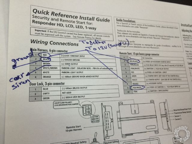
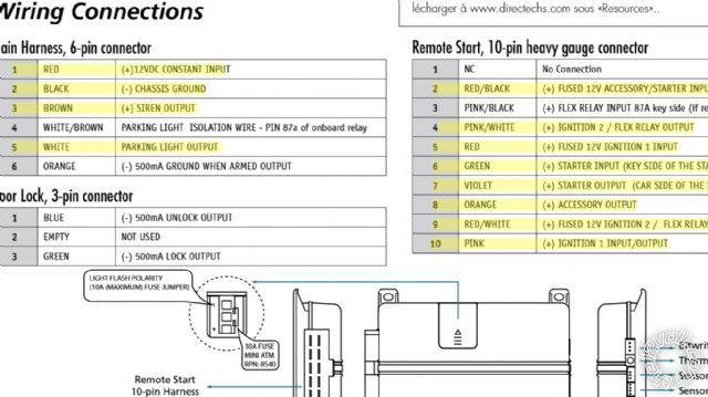
Throw away your diagram on the previous page, you need all 3 on H3 powered from a constant 12V+ source, RED / white, RED / black and red.
Also red on H1
Black on H1 goes to ground, brown to engine bay (Siren).
Yet again, follow the type 2 diagram.
-------------
Amateurs assume, don't test and have problems; pros test first. I am not a free install service.
Read the installation manual, do a search here or online for your vehicle wiring before posting.
Posted By: wissam1981
Date Posted: August 25, 2014 at 3:17 AM
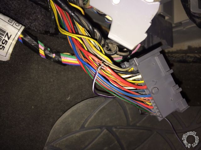
1- please confirm these wiring in the below images,
2- do i need another wires to hooked up ???
Posted By: wissam1981
Date Posted: August 25, 2014 at 3:20 AM
and what about the ( Diagnostic Connector OBD2 ) should i hooked up with the DBall2 ????
Posted By: wissam1981
Date Posted: August 25, 2014 at 4:01 AM
wissam1981 wrote:
1- please confirm these wiring in the below images,
2- do i need another wires to hooked up ???
i missed the RED on H3/5 in the above image
Posted By: howie ll
Date Posted: August 25, 2014 at 6:03 AM
Including the red yes.
-------------
Amateurs assume, don't test and have problems; pros test first. I am not a free install service.
Read the installation manual, do a search here or online for your vehicle wiring before posting.
Posted By: wissam1981
Date Posted: August 25, 2014 at 7:28 AM
so, this is all i need ????
Posted By: howie ll
Date Posted: August 25, 2014 at 7:33 AM
Just follow the Xpresskit type diagram on page 4.
-------------
Amateurs assume, don't test and have problems; pros test first. I am not a free install service.
Read the installation manual, do a search here or online for your vehicle wiring before posting.
Posted By: wissam1981
Date Posted: August 25, 2014 at 8:20 AM
wissam1981 wrote:
and what about the ( Diagnostic Connector OBD2 ) should i hooked up with the DBall2 ????
howie i need to know about this connector, should i connect it to DBall2 ???
Posted By: catback
Date Posted: August 25, 2014 at 8:24 AM
wissam1981 wrote:
and what about the ( Diagnostic Connector OBD2 ) should i hooked up with the DBall2 ????
Didn't you say your car DOES NOT HAVE an OBD2 port?
Posted By: howie ll
Date Posted: August 25, 2014 at 8:28 AM
CB No car built after 98 doesn't have an OBD port.
-------------
Amateurs assume, don't test and have problems; pros test first. I am not a free install service.
Read the installation manual, do a search here or online for your vehicle wiring before posting.
Posted By: howie ll
Date Posted: August 25, 2014 at 8:36 AM
Cat back, please empty your PM inbox, been trying to PM you for two days!
-------------
Amateurs assume, don't test and have problems; pros test first. I am not a free install service.
Read the installation manual, do a search here or online for your vehicle wiring before posting.
Posted By: catback
Date Posted: August 25, 2014 at 8:36 AM
Howie, just going by what the owner has said, no factory security and no OBD2 said the owner. On these parts, OBD2 has been around since '96 and is mandatory of auto manufacturers.
Posted By: howie ll
Date Posted: August 25, 2014 at 8:38 AM
Under dash, left hand side and as I said before, body CAN wires also at BCM and driver;s door loom.
-------------
Amateurs assume, don't test and have problems; pros test first. I am not a free install service.
Read the installation manual, do a search here or online for your vehicle wiring before posting.
Posted By: wissam1981
Date Posted: August 25, 2014 at 9:06 AM
Guys, this is my final, i need a conformation
DBall2 To Viper
1- D2D cable
2- D10/9 pink (+) { ignition input } to H1/1 Red (+)12v constant input
3- tan/black HSCAN highto OBD2
4- tan HSCAN low to OBD2
Viper to Car
1- H6/2 black (-) { Chassis Ground }to Ground ( Car Body )
2- H6/4 WHITE/ brown { parking light } to parking light (+)
3- H10/5 Red (+) fused 12v ignition 1 input to 12v constant white (+)????????
4- H10/6 Green (+) starter input ( key side of the starter kill ) to starter white (+)
5- Red (+)12v constant input to 12v Black (+)
6- H10/8 Accessory output (+) orange to orange pin 3
7- H6/3 brown (+) siren output to car siren
8- H10/2 RED / black (+) fused 12v acc. / starter input to 12v constant
9- H10/5 red (+) fused 12v ignition 1 input to 12v constant
10- H10/9 RED / white (+) fused 12v ignition 2 / flex relay input 87 to 12v constant
DBall2 to Car
1- D10/9 pink (+) ignition input to ignition 1 blue (+)
Posted By: howie ll
Date Posted: August 25, 2014 at 9:31 AM
I give up.
-------------
Amateurs assume, don't test and have problems; pros test first. I am not a free install service.
Read the installation manual, do a search here or online for your vehicle wiring before posting.
Posted By: wissam1981
Date Posted: August 25, 2014 at 9:35 AM
no no no no
you are my only hope, please
Posted By: howie ll
Date Posted: August 25, 2014 at 9:46 AM
You will never finish this you've got half of the above wrong!
Why WHITE/ brown when it says white?
I've NEVER used the WHITE/ brown.
Pink at DB-ALL black plug to pink at H3 to blue at ignition switch.
H3 red,RED / white and RED / black to black at ignition switch OR main (+) battery feed at fuse box. Battery feed = 12V+ constant.
Cut white starter lead, H3 Green to key side H3 Purple to starter side.
Others are correct.
-------------
Amateurs assume, don't test and have problems; pros test first. I am not a free install service.
Read the installation manual, do a search here or online for your vehicle wiring before posting.
Posted By: wissam1981
Date Posted: August 25, 2014 at 10:26 AM
thank you, you didn't give up on me.
1- all the above make scene now , but i didn't get the last part ( Cut white starter lead, H3 Green to key side H3 Purple to starter side )
2- about the light flash polarity, which side should i put the fuse ??
Posted By: howie ll
Date Posted: August 25, 2014 at 10:32 AM
Positive.
-------------
Amateurs assume, don't test and have problems; pros test first. I am not a free install service.
Read the installation manual, do a search here or online for your vehicle wiring before posting.
Posted By: howie ll
Date Posted: August 25, 2014 at 11:55 AM
Here's a diagram except it it may not work, something Catback said earlier about not needing a DB-ALL2 at all if you don't have an immobiliser.
Try it this way first:- hyundai.png
If the locks and door triggers don't work go to the section above Downloads/Manuals and enter 2019 Hyundai Elantra that will show you how to hardwire it. ------------- Amateurs assume, don't test and have problems; pros test first. I am not a free install service.
Read the installation manual, do a search here or online for your vehicle wiring before posting.
Posted By: wissam1981
Date Posted: August 25, 2014 at 12:58 PM
Posted By: howie ll
Date Posted: August 25, 2014 at 1:00 PM
Cut that green wire short, not used in this application all other photos correct.
-------------
Amateurs assume, don't test and have problems; pros test first. I am not a free install service.
Read the installation manual, do a search here or online for your vehicle wiring before posting.
Posted By: howie ll
Date Posted: August 25, 2014 at 1:03 PM
Just a thought, if your car was made in Turkey for the European market it WILL have an immobiliser. If it is a US market car then no.
Easy way to tell. If US your speedo will be in miles, if Euro kilometres.
Also your running lights will be amber if US. If European white front, red back and amber indicators.
European cars have a resat fog light, US do not.
-------------
Amateurs assume, don't test and have problems; pros test first. I am not a free install service.
Read the installation manual, do a search here or online for your vehicle wiring before posting.
Posted By: wissam1981
Date Posted: August 25, 2014 at 1:04 PM
Good
what about the other green wire, should i cut it too ???
Posted By: wissam1981
Date Posted: August 25, 2014 at 1:06 PM
made in korea
Posted By: howie ll
Date Posted: August 25, 2014 at 1:09 PM
Kilometres or MPH?
Just cut the long loose wire, NOT the loop.
-------------
Amateurs assume, don't test and have problems; pros test first. I am not a free install service.
Read the installation manual, do a search here or online for your vehicle wiring before posting.
Posted By: wissam1981
Date Posted: August 25, 2014 at 1:11 PM
howie ll wrote:
Kilometres or MPH?
Just cut the long loose wire, NOT the loop.
Kilometres
Posted By: howie ll
Date Posted: August 25, 2014 at 1:15 PM
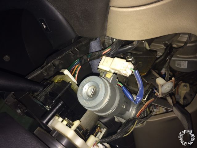
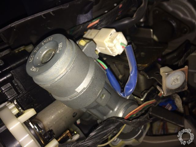
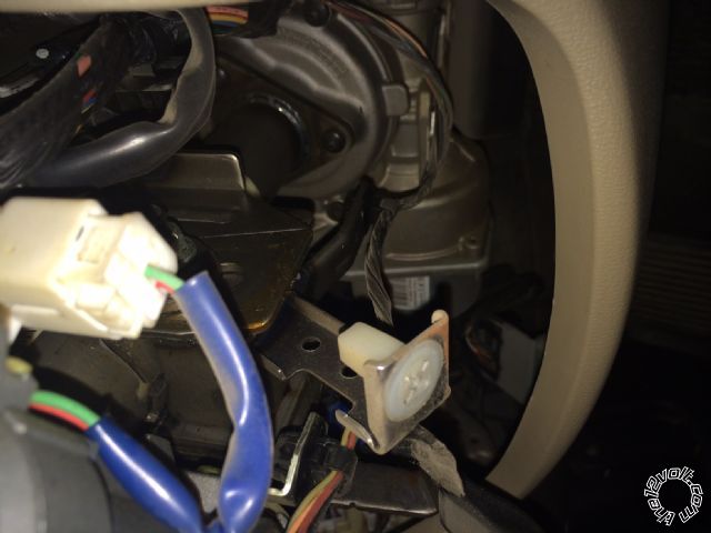
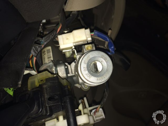
Euro spec unless a direct import, bet you have an immobiliser the. Remove cowling from steering column to show a picture of the ignition switch please.
-------------
Amateurs assume, don't test and have problems; pros test first. I am not a free install service.
Read the installation manual, do a search here or online for your vehicle wiring before posting.
Posted By: wissam1981
Date Posted: August 25, 2014 at 1:33 PM
howie ll wrote:
Euro spec unless a direct import, bet you have an immobiliser the. Remove cowling from steering column to show a picture of the ignition switch please.
Posted By: howie ll
Date Posted: August 25, 2014 at 1:40 PM
OK apologies no immobiliser!
Scrap the DB-ALL2 and follow the wiring diagram I told you about in the Downloads/Manuals section.
-------------
Amateurs assume, don't test and have problems; pros test first. I am not a free install service.
Read the installation manual, do a search here or online for your vehicle wiring before posting.
Posted By: wissam1981
Date Posted: August 25, 2014 at 1:50 PM
So i don't need the DBall2
i downloaded the manual for elantra 2010. but i couldn't understand it
can you give me clarification ?
Posted By: howie ll
Date Posted: August 25, 2014 at 1:54 PM
No. Sorry, it's a hardwire job.
-------------
Amateurs assume, don't test and have problems; pros test first. I am not a free install service.
Read the installation manual, do a search here or online for your vehicle wiring before posting.
Posted By: wissam1981
Date Posted: August 25, 2014 at 1:56 PM
is there any way to use the DBall2 ?
Posted By: howie ll
Date Posted: August 25, 2014 at 2:01 PM
Try it first with the DB-ALL2 but if you don't get door locks, door, hood and trunk triggers then you will have to go the hardwire route.
-------------
Amateurs assume, don't test and have problems; pros test first. I am not a free install service.
Read the installation manual, do a search here or online for your vehicle wiring before posting.
Posted By: wissam1981
Date Posted: August 25, 2014 at 2:37 PM
about the elantra downloaded file that you provide me in the download/manual section
what this means { 12 Volts red to black (40A) }
what red to black means ????
Posted By: howie ll
Date Posted: August 25, 2014 at 2:40 PM
There might be a blue plug halfway down the steering column on the left hand side. The colours change either side.
Can I go now for tonight, you know I have life to lead😱
-------------
Amateurs assume, don't test and have problems; pros test first. I am not a free install service.
Read the installation manual, do a search here or online for your vehicle wiring before posting.
Posted By: wissam1981
Date Posted: August 25, 2014 at 2:42 PM
howie ll wrote:
Try it first with the DB-ALL2 but if you don't get door locks, door, hood and trunk triggers then you will have to go the hardwire route.
just last question, what is percentage % of DBall2 to work with my vechile ?
Posted By: wissam1981
Date Posted: August 26, 2014 at 8:10 AM
just last question, what is percentage % of DBall2 to work with my vehicle ???
Posted By: howie ll
Date Posted: August 26, 2014 at 9:23 AM
No idea, sorry.
-------------
Amateurs assume, don't test and have problems; pros test first. I am not a free install service.
Read the installation manual, do a search here or online for your vehicle wiring before posting.
Posted By: catback
Date Posted: August 26, 2014 at 9:33 AM
wissam1981 wrote:
just last question, what is percentage % of DBall2 to work with my vehicle ???
The same percentage/odds that your 2010 elantra is a 2011 model.
Posted By: howie ll
Date Posted: August 26, 2014 at 9:36 AM
Ha Ha! Just try it and we'll see what the CAN wires and DB control.
-------------
Amateurs assume, don't test and have problems; pros test first. I am not a free install service.
Read the installation manual, do a search here or online for your vehicle wiring before posting.
Posted By: wissam1981
Date Posted: August 26, 2014 at 9:57 AM
[/QUOTE]
The same percentage/odds that your 2010 elantra is a 2011 model.[/QUOTE]
what you mean by that ???
Posted By: wissam1981
Date Posted: August 26, 2014 at 10:14 AM
you mean that my vehicle is 2011 ???
Posted By: wissam1981
Date Posted: August 26, 2014 at 1:07 PM
Guys, i am planning to make the installation with DBall2 ( as howie said ), and if this wouldn't work, i have to do it with out the DBall2 ( hardwire )
So, i study viper diagram and marked ( as long my knowledge ) all the wires i need to do this installation as below, i need a conformation from you guys.
1- H6/1 (+)12VDC CONSTANT INPUT 12v
2- H6/2 (-) CHASSIS GROUND Ground
3- H6?3 (+) SIREN OUTPUT Siren
4- H6/5 PARKING LIGHT OUTPUT
5- H10/2 RED / BLACK (+) FUSED 12V ACCESSORY/STARTER INPUT 12v
6- H10/5 RED (+) FUSED 12V IGNITION 1 INPUT 12v
7- H10/6 GREEN (+) STARTER INPUT (KEY SIDE OF THE STARTER KILL) Starter KEY SIDE OF THE STARTER KILL
8- H10/7 VIOLET (+) STARTER OUTPUT (CAR SIDE OF THE STARTER KILL) starter CAR SIDE OF THE STARTER KILL
9- H10/8 ORANGE (+) ACCESSORY OUTPUT ACCESSORY
10- H10/9 RED / WHITE (+) FUSED 12V IGNITION 2 / FLEX RELAY INPUT 87 12v
11- H10/10 PINK (+) IGNITION 1 INPUT/OUTPUTIGNITION 1
12- H24/18 VIOLET (+) DOOR INPUT ???????
13- H24/20 BROWN (+) BRAKE SHUTDOWN INPUT brake wire
do i need a relay ?
Posted By: howie ll
Date Posted: August 26, 2014 at 1:29 PM
H2 Violet not needed you'll use the green but even then only if the DB doesn't work.
-------------
Amateurs assume, don't test and have problems; pros test first. I am not a free install service.
Read the installation manual, do a search here or online for your vehicle wiring before posting.
Posted By: wissam1981
Date Posted: August 26, 2014 at 1:37 PM
howie ll wrote:
H2 Violet not needed you'll use the green but even then only if the DB doesn't work.
So, from your reply i noticed that these wires all i need, right?
what about relays ?
Posted By: howie ll
Date Posted: August 26, 2014 at 1:40 PM
No sir, don't even go there.
-------------
Amateurs assume, don't test and have problems; pros test first. I am not a free install service.
Read the installation manual, do a search here or online for your vehicle wiring before posting.
Posted By: wissam1981
Date Posted: August 29, 2014 at 8:45 AM
today, i tried the to hook up the viper with Dball2, with no luck
is there in this forum any case similar to my case ( no transponder ) with viper so i can figure out the hardwire of the viper and my vehicle ????
Posted By: catback
Date Posted: August 29, 2014 at 9:46 AM
There are pictorials on here and youtube videos covering remote starts. Maybe you can learn from them.
Posted By: wissam1981
Date Posted: August 29, 2014 at 10:38 AM
catback wrote:
There are pictorials on here and youtube videos covering remote starts. Maybe you can learn from them.
please i searched this forum, youtube and the web, i couldn't find a case similar my mine
please i need from you just to list the wires( viper without DBall2) that should be connected to my car.
should i go to W2W ???
Posted By: catback
Date Posted: August 30, 2014 at 10:35 AM
Very little will lay out putting a 5706v into a 2010 elantra down to every detail. But much can be learned about installing remote starts, the wires, and what they do by seeing how some are done. If you just want it put in and done, paying someone to do it for you is as easy as it gets. If you want to actually learn and/or feel self-accomplishment, again lots of pictorials and youtube videos that will show you many installations of viper units (which are all very similar). Even if it's not a viper unit, R/S units are fairly standard in what wires and functions they have so you can even learn from them.
As to your question on what wires to hook up, I answered this in this thread some pages ago when you posted your highlighted diagram.
Once you omit (take out) the dball2 from the installation there is no W2W or D2D, there is only hardwire. And yes you should hardwire because it's the only way I or DEI (manufacturer of the 5706 and the dball2) think it will ever work.
Posted By: howie ll
Date Posted: August 30, 2014 at 10:42 AM
And I've already posted the hardwire directions for this vehicle to the Downloads/Manuals section. Just follow it.
-------------
Amateurs assume, don't test and have problems; pros test first. I am not a free install service.
Read the installation manual, do a search here or online for your vehicle wiring before posting.
Posted By: wissam1981
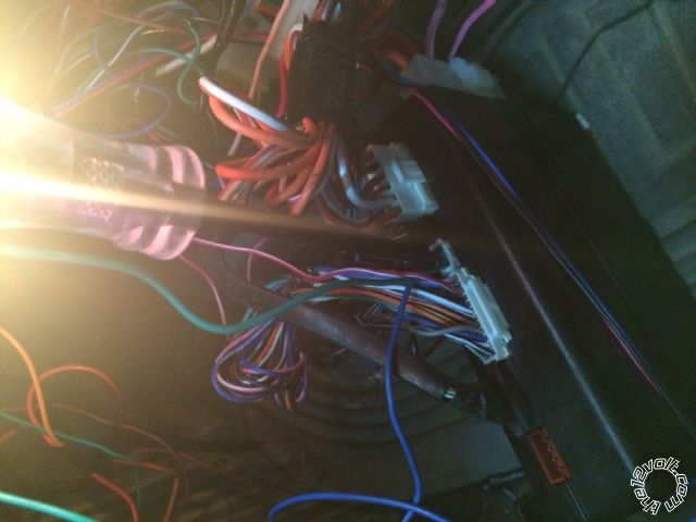
Date Posted: September 03, 2014 at 1:32 AM
Hello,
Guys see the images below, and tell me what you think.
are these wires all i need to hook up with my vehicle???
Posted By: howie ll
Date Posted: September 03, 2014 at 1:48 AM
Yes but in your climate is the rear defogger needed?
H2/9 Hood , H2/10 trunk and H2/12 TACH also required.
-------------
Amateurs assume, don't test and have problems; pros test first. I am not a free install service.
Read the installation manual, do a search here or online for your vehicle wiring before posting.
Posted By: wissam1981
Date Posted: September 03, 2014 at 2:07 AM
Thank you for your quick reply howie, i appreciate it
1- i didn't understand the H2/10
2- is there an option in the viper to control the AC ( Air Conditioner )
from Viper remote?, if yes , do i need other wires to hook ?
3- image updated
Posted By: wissam1981
Date Posted: September 03, 2014 at 5:19 AM
howei, the H2/13 also i couldn't understand
should i connect it to Ground cause my vehicle is automatic transmission???
Posted By: howie ll
Date Posted: September 03, 2014 at 3:51 PM
H2/10 to GREEN/ black driver kick, gray 39 pin plug, pin 11.
Yes connect it to ground.
-------------
Amateurs assume, don't test and have problems; pros test first. I am not a free install service.
Read the installation manual, do a search here or online for your vehicle wiring before posting.
Posted By: wissam1981
Date Posted: September 04, 2014 at 8:11 AM
howie, i need some clarification to wires listed below please
1- H2/15 and H2/18 ?
2- H2/3 ?
3- H2/4 To ( Dome Supervision yellow - driver kick, gray 39 pin plug, pin 14 )
4- H2/20 To ( Brake Wire black + driver kick, gray 39 pin plug, pin 34 ) OR ( Parking Brake blue - dash fuse box, rear, white 20 pin plug (C), pin 8 ) ??
5- i think i need H2/5 (-) 200ma status output ?
Thanks in Advance.
Posted By: wissam1981
Date Posted: September 04, 2014 at 1:27 PM
Final Confirmation Please
H1/1 Red (12v) Constant Input
H3/2 RED / BLACK (+) FUSED 12V ACCESSORY/STARTER INPUT
H3/5 RED (+) FUSED 12V IGNITION 1 INPUT
H3/10 PINK (+) IGNITION 1 INPUT/OUTPUT
H3/9 RED / WHITE (+) FUSED 12V IGNITION 2 / FLEX RELAY INPUT 87
All the above to 12 Volts red to black (40A) + ignition switch, white 6 pin plug, pin 5
H1/2 Black (-) CHASSIS GROUND Vehicle ground
H1/3 (+) SIREN OUTPUT Siren
H1/5 PARKING LIGHT OUTPUT ( Parking Lights (+) pink (L), BROWN / orange (R) + dash fuse box, rear, white 30 pin plug (F), pins 22 and 6 ) OR ( Parking Lights (-) orange - headlight switch, white 14 pin plug, pin 8 )
H2/3 RED / White (-) 200mA TRUNK RELEASE OUTPUT ????????
H2/4 BLACK/ Yallow (-) 200mA DOME LIGHT OUTPUT Dome Supervision yellow - driver kick, gray 39 pin plug, pin 14
H2/9 Gray (-) HOOD PIN INPUT (NC OR NO) Hood Pin in Viper
H2/10 (-) TRUNK PIN/INSTANT TRIGGER INPUT (N/C OR N/O) Trunk/Hatch Pin GREEN/ black - driver kick, gray 39 pin plug, pin 11
H2/12 VIOLET/WHITE* TACHOMETER INPUT Tachometer blue/red (front of plug) to red (back of plug) ac passenger kick, gray 39 pin plug, pin 5
H2/13 BLACK/ WHITE** (-) NEUTRAL SAFETY /PARKING BRAKE INPUT to Vehicle Ground
H2/15 Green (-) DOOR INPUT ????????
H2/20 H2/20 To ( Brake Wire black + driver kick, gray 39 pin plug, pin 34 ) OR ( Parking Brake blue - dash fuse box, rear, white 20 pin plug (C), pin 8 )
H3/6 GREEN (+) STARTER INPUT (KEY SIDE OF THE STARTER KILL) Starter BLACK / YELLOW to white + ignition switch, ( To Key side )
H3/7 VIOLET (+) STARTER OUTPUT (CAR SIDE OF THE STARTER KILL) Starter BLACK / YELLOW to white + ignition switch, ( to Car Side )
H3/8 ORANGE (+) ACCESSORY OUTPUT Accessory white to orange + ignition switch, white 6 pin plug, pin 3
Posted By: howie ll
Date Posted: September 04, 2014 at 2:28 PM
Do nothing!
You are about as wrong as it's possible to be.
I'll get back to you with (lots of) corrections tomorrow.
-------------
Amateurs assume, don't test and have problems; pros test first. I am not a free install service.
Read the installation manual, do a search here or online for your vehicle wiring before posting.
Posted By: howie ll
Date Posted: September 04, 2014 at 5:02 PM
H1/1 Red (12v) Constant Input
H3/2 RED / BLACK (+) FUSED 12V ACCESSORY/STARTER INPUT
H3/5 RED (+) FUSED 12V IGNITION 1 INPUT
H3/10 PINK (+) IGNITION 1 INPUT/OUTPUT
H3/9 RED / WHITE (+) FUSED 12V IGNITION 2 / FLEX RELAY INPUT 87
All the above to 12 Volts red to black (40A) + ignition switch, white 6 pin plug, pin 5
NO Pink to ign, if 2nd ign, pink/white to second ignition.
H1/5 PARKING LIGHT OUTPUT You will want left and right indicators, at steering column loom.
H2/3 RED / White (-) 200mA TRUNK RELEASE OUTPUT ????
Is there an electric trunk release? You can look and refer to the instructions, I told you so many times where they are I'm giving up.
H2/4 BLACK / YELLOW (-) 200mA DOME LIGHT OUTPUT Again! I told you not to bother.
H2/15 Green (-) DOOR INPUT ??? Again repeating the same questions for which either the list I posted or previous answers should tell you.
-------------
Amateurs assume, don't test and have problems; pros test first. I am not a free install service.
Read the installation manual, do a search here or online for your vehicle wiring before posting.
Posted By: wissam1981
Date Posted: September 05, 2014 at 3:21 PM
1- what the step after hooking all wires
2- i don't understand the ( learning the Tach ), should i do there steps ?
3- regarding the remote, should i pair it or its already paired to the system ?
Posted By: howie ll
Date Posted: September 06, 2014 at 2:35 AM
1) See 2 and 3
2) Read the programming instructions H2/15 GREEN must be connected to a door pin (see fitting guide) or GROUNDED.
3) Should already be paired try an on off first with each remote once the wiring is completed then go on to program tach.
-------------
Amateurs assume, don't test and have problems; pros test first. I am not a free install service.
Read the installation manual, do a search here or online for your vehicle wiring before posting.
Posted By: wissam1981
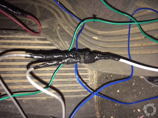
Date Posted: September 06, 2014 at 3:18 AM
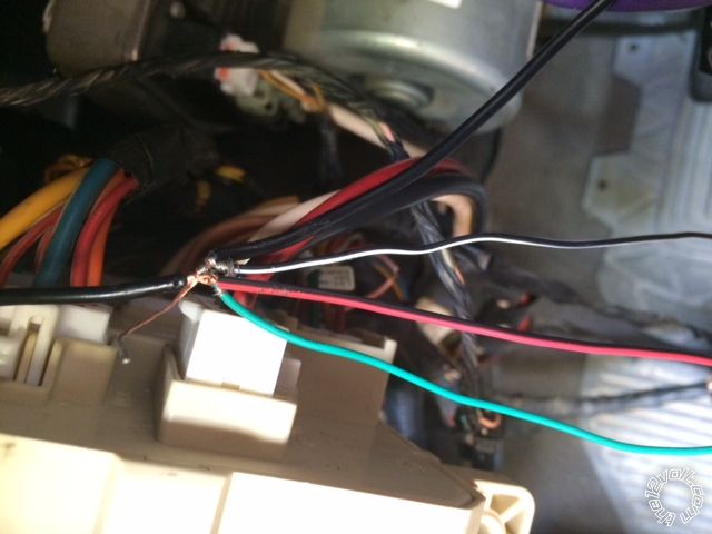
please check this image ( Tachometer ) Connecting, is this image correct ?
Posted By: howie ll
Date Posted: September 06, 2014 at 3:25 AM
Yes it's correct although you might need to place more solder on that joint. It must sink into both wires and be shiny.
-------------
Amateurs assume, don't test and have problems; pros test first. I am not a free install service.
Read the installation manual, do a search here or online for your vehicle wiring before posting.
Posted By: wissam1981
Date Posted: September 06, 2014 at 3:37 AM
i am having trouble finding the ( parking light ) on my vehicle, please help
Posted By: howie ll
Date Posted: September 06, 2014 at 3:43 AM
You need to go to the direction indicators (turn signal)left and right as in the instructions. Place internal fuse in the (+) position then split the white wire via 2 X 1N5404 diodes (any electronics store, repair facility etc.) bands away from 5706 to each wire.
-------------
Amateurs assume, don't test and have problems; pros test first. I am not a free install service.
Read the installation manual, do a search here or online for your vehicle wiring before posting.
Posted By: wissam1981
Date Posted: September 06, 2014 at 3:50 AM
is it required for programming ? if not, can i connect it later ?
Posted By: howie ll
Date Posted: September 06, 2014 at 3:53 AM
No.
-------------
Amateurs assume, don't test and have problems; pros test first. I am not a free install service.
Read the installation manual, do a search here or online for your vehicle wiring before posting.
Posted By: wissam1981
Date Posted: September 06, 2014 at 4:32 AM
Posted By: wissam1981
Date Posted: September 06, 2014 at 4:47 AM
howie ll wrote:
1) See 2 and 3
2) Read the programming instructions H2/15 GREEN must be connected to a door pin (see fitting guide) or GROUNDED.
this is what you said
Posted By: howie ll
Date Posted: September 06, 2014 at 4:59 AM
What else apart from the BLACK/ white is connected to ground?
Also is the pink on H3 connected to ignition?
-------------
Amateurs assume, don't test and have problems; pros test first. I am not a free install service.
Read the installation manual, do a search here or online for your vehicle wiring before posting.
Posted By: wissam1981
Date Posted: September 06, 2014 at 5:03 AM
BLACK/ white (-) NEUTRAL SAFETY /PARKING BRAKE INPUT yes connected to ground
yes pink connected to ignition
Posted By: howie ll
Date Posted: September 06, 2014 at 5:34 AM
I see a RED / black also connected.
-------------
Amateurs assume, don't test and have problems; pros test first. I am not a free install service.
Read the installation manual, do a search here or online for your vehicle wiring before posting.
Posted By: wissam1981
Date Posted: September 06, 2014 at 5:39 AM
wissam1981 wrote:
it wouldn't learn the TACH
you mean this image ?
RED / black for siren
Posted By: howie ll
Date Posted: September 06, 2014 at 5:41 AM
RED / black for siren goes to brown on H1, black on siren to ground.
It means you've done something else wrong. I don't know what.
-------------
Amateurs assume, don't test and have problems; pros test first. I am not a free install service.
Read the installation manual, do a search here or online for your vehicle wiring before posting.
Posted By: wissam1981
Date Posted: September 06, 2014 at 5:49 AM
just double check
H1 (+)12VDC CONSTANT INPUT
H3/2 RED / BLACK (+) FUSED 12V ACCESSORY/STARTER INPUT
H3/5 RED (+) FUSED 12V IGNITION 1 INPUT
H3/9 RED / WHITE (+) FUSED 12V IGNITION 2 / FLEX RELAY INPUT 87
all to 12v ignition switch
do i need H3/9 cause my vehicle don't have ignition 2
right?
Posted By: howie ll
Date Posted: September 06, 2014 at 6:14 AM
H3/2 RED / BLACK (+) FUSED 12V ACCESSORY/STARTER INPUT
H3/5 RED (+) FUSED 12V IGNITION 1 INPUT
H3/9 RED / WHITE (+) FUSED 12V IGNITION 2 / FLEX RELAY INPUT 87
NO! All of the above to a constant power source.
do i need H3/9 cause my vehicle don't have ignition 2
No.
-------------
Amateurs assume, don't test and have problems; pros test first. I am not a free install service.
Read the installation manual, do a search here or online for your vehicle wiring before posting.
Posted By: wissam1981
Date Posted: September 06, 2014 at 8:59 AM
howie, when i did the statup/shutdown diagnose
the LED flashed 7 times, whats that mean
Posted By: howie ll
Date Posted: September 06, 2014 at 9:12 AM
Needs to be set up/programmed as an auto, menu 3 option 1 again please refer to the instructions which came in the box.
-------------
Amateurs assume, don't test and have problems; pros test first. I am not a free install service.
Read the installation manual, do a search here or online for your vehicle wiring before posting.
Posted By: wissam1981
Date Posted: September 06, 2014 at 11:19 AM
howie, i just wondering about lock and unlock the doors, how they works without hooking the 3 pin connector in viper ?
Posted By: howie ll
Date Posted: September 06, 2014 at 11:21 AM
They don't without the 3 pin connector.
-------------
Amateurs assume, don't test and have problems; pros test first. I am not a free install service.
Read the installation manual, do a search here or online for your vehicle wiring before posting.
Posted By: wissam1981
Date Posted: September 06, 2014 at 11:26 AM
Hm, right
so where should hooked up, is it required for programming.
you know that im having trouble with tach learning, so i am revising all the wires.
Posted By: howie ll
Date Posted: September 06, 2014 at 11:32 AM
To the door lock triggers (NOT door triggers but lock and unlock triggers, marked power lock and power unlock in the install guide).
Not required for programming.
First all these things, door locks, triggers indicators (lights) should have been done first.
Second I need a life, all of the last 8 or so pages could have bee answered by you by looking at your two reference sheets, the one that comes in the box and the vehicle reference chart I downloaded to the Downloads/Manuals section.
-------------
Amateurs assume, don't test and have problems; pros test first. I am not a free install service.
Read the installation manual, do a search here or online for your vehicle wiring before posting.
Posted By: wissam1981
Date Posted: September 06, 2014 at 1:00 PM
howie, i finally start the vehicle with the remote, the problem was in menu 3, opt 1 , by default it set to manual, i change it to auto, and it's started
1- is that means that R/S learned Tach ?
2-now i am facing the air conditioner wouldn't work with remote start
the air conditioner work only when trying start the vehicle with key. why ?
any help, i know i caused you headache, but i don't know anyone elease but you.
Please noted that i am still not connecting these wires
1- hood pin wire
2- green door wire ( i just connected it for programming ), i will connect it later to Door pin.
3- door lock and unlock wires ( in 3 Pin Connector )
thank you for all your hard work with me, i appreciated
Posted By: howie ll
Date Posted: September 06, 2014 at 4:31 PM
AC might only work if you set the levels beforehand, leave the vehicle, arm then try the R/S that should bring on the AC automatically, that's how it works on most vehicles.
-------------
Amateurs assume, don't test and have problems; pros test first. I am not a free install service.
Read the installation manual, do a search here or online for your vehicle wiring before posting.
Posted By: wissam1981
Date Posted: September 08, 2014 at 6:02 AM
howie,
1- i just wondering what the benefit of TACH wire (viper), what if i wouldn't connect it
2- i start my vehicle with R/S, when i pressed the brake the vehicle shutdown, is this normal.
Posted By: howie ll
Date Posted: September 08, 2014 at 8:32 AM
Yes, read the owners' manual, takeover from remote start.
You can run it in "virtual" tach without connecting to tach but it doesn't work as well.
-------------
Amateurs assume, don't test and have problems; pros test first. I am not a free install service.
Read the installation manual, do a search here or online for your vehicle wiring before posting.
Posted By: catback
Date Posted: September 08, 2014 at 9:20 AM
wissam1981 wrote:
2- i start my vehicle with R/S, when i pressed the brake the vehicle shutdown, is this normal.
Yes it is normal. Insert key and turn to ON/RUN and then press on brake if you wish to drive car.
Posted By: wissam1981
Date Posted: September 08, 2014 at 1:00 PM
catback wrote:
wissam1981 wrote:
2- i start my vehicle with R/S, when i pressed the brake the vehicle shutdown, is this normal.
Yes it is normal. Insert key and turn to ON/RUN and then press on brake if you wish to drive car.
okay, i get it now thanks
now i have last three problems.
1- problem with ( lock and unlock wires ), when i test the 3 pin connecter( By tester light) , its (+) must be (-) . Why?
2- when i try to connect the parking wires (white) in 6-pin connector and trying to start the vehicle by remote, it's started for about 15 sec. and shutdown for it self, ( this process take 3 times ) and finally shutdown. but when i disconnect this wire the vehicle operate normally.
3- you remember that i told you about AC not working, i tried your advice by arming the vehicle and leave it and starting it ( but i didn't get how to set levels as you said ), same issue ( AC not working), so i tried to connect ignition wire (pink) to both wires ( ignition 1 + 2) in ignition switch, it's operate normally and the vehicle AC worked fine, is it save what i did or not ?
Posted By: howie ll
Date Posted: September 08, 2014 at 4:36 PM
Just connect the lock/unblock wires as per the instructions.
But you told me there was only one ignition!
Test the two wires in the ignition loom that flash on and off when you turn on the ignition and move the direction indicator left and right.
Make sure you've set the unit's fuse to POS and split that white wire via 2 X 1N5404 diodes.
You told me there was only one ignition wire, now you're telling me there are two. Use your pink/white for the second ignition,do not join both ignition wires to your pink it will cause very expensive electrical overload problems later on.
-------------
Amateurs assume, don't test and have problems; pros test first. I am not a free install service.
Read the installation manual, do a search here or online for your vehicle wiring before posting.
Posted By: wissam1981
Date Posted: September 08, 2014 at 5:36 PM
i put the PINK/WHITE to ignition 2, and RED / WHITE to 12v source, same issue ( AC not working), do i need a relay on ignition 2 ?
( Just connect the lock/unblock wires as per the instructions), what the instructions says?
( Make sure you've set the unit's fuse to POS and split that white wire via 2 X 1N5404 diodes) i did that with same problem
Posted By: howie ll
Date Posted: September 08, 2014 at 5:39 PM
Then recheck your wiring.
-------------
Amateurs assume, don't test and have problems; pros test first. I am not a free install service.
Read the installation manual, do a search here or online for your vehicle wiring before posting.
Posted By: wissam1981
Date Posted: September 08, 2014 at 6:11 PM
about lock/unlock
Door lock 3 pin connecter
1- blue (-) 500ma unlock output ------- Power Unlock yellow - driver kick, gray 39 pin plug, pin 39
2- Green (-) 500mA LOCK OUTPUT ------- Power Lock green - driver kick, gray 39 pin plug, pin 25
Right?
Posted By: howie ll
Date Posted: September 09, 2014 at 1:27 AM
Yes.
-------------
Amateurs assume, don't test and have problems; pros test first. I am not a free install service.
Read the installation manual, do a search here or online for your vehicle wiring before posting.
Posted By: wissam1981
Date Posted: September 09, 2014 at 4:58 PM
wissam1981 wrote:
about lock/unlock
Door lock 3 pin connecter
1- blue (-) 500ma unlock output ------- Power Unlock yellow - driver kick, gray 39 pin plug, pin 39
2- Green (-) 500mA LOCK OUTPUT ------- Power Lock green - driver kick, gray 39 pin plug, pin 25
Right?
1- i connect it as above and didn't work, any ideas?
is there any programming steps that i should do first ?
2- i am still couldn't do the ( learning Tach ), i follow the steps in the manual, nothing happened, why?
3- i realised that there is feature in Menu 3, option 2 ( tachometer, and virtual Tach )
i am still until now not understanding the benefit of tachometer, and the learning Tach? please can you give me some information about it ?
Posted By: wissam1981
Date Posted: September 09, 2014 at 5:23 PM
please check out these images
1- this is 3 pin harness, as you see the blue wire have power all the time, is this normal ?
it says in the manual (-), i can't understand it
2- i am facing until now the shutdown problem ( when i connect the parking light wire ), so i disconnect it ( for now ) until i figure out whats happening, any ideas ?
P. S. i realise when i connect the parking light wire and start the vehicle, the diodes become overheat. is this normal ?
thanks in advance
Posted By: wissam1981
Date Posted: September 10, 2014 at 12:38 PM
Howie, where are you man, I need you
Posted By: howie ll
Date Posted: September 10, 2014 at 12:47 PM
Make sure the lights fuse in the alarm casing is in the POS (+) position.
-------------
Amateurs assume, don't test and have problems; pros test first. I am not a free install service.
Read the installation manual, do a search here or online for your vehicle wiring before posting.
Posted By: wissam1981
Date Posted: September 10, 2014 at 1:02 PM
im sure
Posted By: wissam1981
Date Posted: September 10, 2014 at 1:17 PM
i just want to solve lock/unlock issue
Posted By: howie ll
Date Posted: September 10, 2014 at 1:22 PM
Again check your wiring, make sure you get a NEG (-) from the green on lock/arm and a Neg (-) from the unlock on unlock/disarm.
-------------
Amateurs assume, don't test and have problems; pros test first. I am not a free install service.
Read the installation manual, do a search here or online for your vehicle wiring before posting.
Posted By: wissam1981
Date Posted: September 10, 2014 at 2:03 PM
about the menu 3, feature 2 ( Engine Checking Mode ), which one (opt.1, opt.2, opt.3, opt.4) is the default option ?
Posted By: howie ll
Date Posted: September 10, 2014 at 2:11 PM
Look at the quick reference guide.
-------------
Amateurs assume, don't test and have problems; pros test first. I am not a free install service.
Read the installation manual, do a search here or online for your vehicle wiring before posting.
Posted By: wissam1981
Date Posted: September 10, 2014 at 2:52 PM
wissam1981 wrote:
about the menu 3, feature 2 ( Engine Checking Mode ), which one (opt.1, opt.2, opt.3, opt.4) is the default option ?
So, i must switch to opt.4 in menu 3 so i can do ( learning Tach ) ?
Posted By: howie ll
Date Posted: September 10, 2014 at 3:45 PM
Yes.
-------------
Amateurs assume, don't test and have problems; pros test first. I am not a free install service.
Read the installation manual, do a search here or online for your vehicle wiring before posting.
Posted By: wissam1981
Date Posted: September 13, 2014 at 10:16 AM
Hello,
1- i rechecked all the wires ( twice ), all features works fine, except Doors ( lock, unlock ), i think the problem in the 3 pin connector, how to this connector ?
2- i switched the Engine Checking Mode ( menu 3, feature 2 ) to off, whats that mean ?
Posted By: howie ll
Date Posted: September 13, 2014 at 10:21 AM
1) Check that with your DMM red probe on 12V+, black probe to green wire your meter shows 12V+ on lock only, then place black probe to blue wire, meter should then show 12V+ on unlock only.
2) Trouble
Menu 3 feature 2 should be tach mode.
-------------
Amateurs assume, don't test and have problems; pros test first. I am not a free install service.
Read the installation manual, do a search here or online for your vehicle wiring before posting.
Posted By: wissam1981
Date Posted: September 13, 2014 at 12:10 PM
howie ll wrote:
1) Check that with your DMM red probe on 12V+, black probe to green wire your meter shows 12V+ on lock only, then place black probe to blue wire, meter should then show 12V+ on unlock only.
.
test it, both give 12v, so the 3 pin connector works just fine.
i am going crazy, i don't know what to do, please i need some ideas?
Posted By: howie ll
Date Posted: September 13, 2014 at 12:22 PM
Test the wires given in the instructions by grounding each in turn, see if that locks and unlocks the car.
-------------
Amateurs assume, don't test and have problems; pros test first. I am not a free install service.
Read the installation manual, do a search here or online for your vehicle wiring before posting.
Posted By: wissam1981
Date Posted: September 13, 2014 at 12:39 PM
howie ll wrote:
Test the wires given in the instructions by grounding each in turn, see if that locks and unlocks the car.
if you mean car wires, i did that, it's normally lock and unlock the car.
this what i did ( to test the green and blue wires ), i disconnect the the 3 pin connector from viper, and hooked up the blue and green wires to car wires ( Yellow and green ), and used light tester and ground each wire, it's lock and unlock the car, ( the wires Green and blue ) without cut in it.
Posted By: catback
Date Posted: September 14, 2014 at 11:22 AM
wissam1981 wrote:
howie ll wrote:
Test the wires given in the instructions by grounding each in turn, see if that locks and unlocks the car.
if you mean car wires, i did that, it's normally lock and unlock the car.
this what i did ( to test the green and blue wires ), i disconnect the the 3 pin connector from viper, and hooked up the blue and green wires to car wires ( Yellow and green ), and used light tester and ground each wire, it's lock and unlock the car, ( the wires Green and blue ) without cut in it.
Plug it back in to the viper and it will do the same thing (work).
Posted By: wissam1981
Date Posted: September 15, 2014 at 3:10 AM
same issue
Posted By: wissam1981
Date Posted: September 15, 2014 at 3:32 AM
same iusse
Posted By: howie ll
Date Posted: September 15, 2014 at 3:41 AM
You've tested the vehicle wires as correct, you've tested the lock/unlock outputs as correct, you've joined together don't work, what does that tell you?
-------------
Amateurs assume, don't test and have problems; pros test first. I am not a free install service.
Read the installation manual, do a search here or online for your vehicle wiring before posting.
Posted By: wissam1981
Date Posted: September 15, 2014 at 5:17 AM
Posted By: howie ll
Date Posted: September 15, 2014 at 5:25 AM
And you're the one doing it. Want to drive over to me?
-------------
Amateurs assume, don't test and have problems; pros test first. I am not a free install service.
Read the installation manual, do a search here or online for your vehicle wiring before posting.
Posted By: howie ll
Date Posted: September 15, 2014 at 5:26 AM
Tell me the voltage between H1 black and H1 red.
-------------
Amateurs assume, don't test and have problems; pros test first. I am not a free install service.
Read the installation manual, do a search here or online for your vehicle wiring before posting.
Posted By: catback
Date Posted: September 15, 2014 at 8:48 AM
Make sure your plugging the 3-pin door lock connector into the proper port on the 5706v. The blue wire should test as ground during unlock and the green should test as ground during lock with the remote. The 3-pin plug fits in other spots so ensure your putting it in the right spot (this mistake has been done on here before).
I can't stress enough to connect to the correct green and yellow wires on the vehicle. The "driver kick, gray 39 pin plug" has a multitude of green and yellow, namely yellow that are in some way linked to door lock function. When aiming for a particular function using the vehicle wiring info you have to ensure that not only is the color correct but also that your at the correct pin number that has that color.
Howie, makes a valid point. The system must be fully installed with antenna and power for the remote to work the locks. The siren and lights should both do their thing when you press unlock or lock on the fob.
While not generally the case, the remote may need to be learned to the system if all the above is good but the 5706v doesn't respond to the remote. *This is an extra tidbit that shouldn't apply as you've tested the 5706v unlock/lock output*
In summary, with power, ground, antenna, a programmed remote, and proper connection of the door lock harness to both the vehicle and the 5706v the door locks should work.
Posted By: catback
Date Posted: September 15, 2014 at 8:50 AM
I should also add when are the door locks not working via 5706v remote? All the time (never works)? During remote start? With the key in the ignition? or some other scenario?
Posted By: wissam1981
Date Posted: September 18, 2014 at 12:17 PM
catback wrote:
I should also add when are the door locks not working via 5706v remote? All the time (never works)? During remote start? With the key in the ignition? or some other scenario?
1- All the time (never works)
2- i will post a video demonstrating the issue that i have.
Posted By: jgerard81
Date Posted: September 18, 2014 at 1:09 PM
When you tested the red DMM probe to 12v(+) and the black probe to the green and blue wire of the viper, did you use the viper key fob to lock and unlock, or the factory switch?
Posted By: wissam1981
Date Posted: September 18, 2014 at 1:44 PM
jgerard81 wrote:
When you tested the red DMM probe to 12v(+) and the black probe to the green and blue wire of the viper, did you use the viper key fob to lock and unlock, or the factory switch?
of course viper remote NOT factory remote
Posted By: jgerard81
Date Posted: September 18, 2014 at 4:09 PM
Since manually grounding the green or blue wire causes the vehicle to lock or unlock, it sounds like the vehicle may be detecting an unexpected level of resistance at those wires when the Viper grounds them. If it were me, I would try using the green and blue wires to trigger a relay
Posted By: howie ll
Date Posted: September 18, 2014 at 4:12 PM
Or measure the current drawn when grounding should't be more than 150 milliamps.
-------------
Amateurs assume, don't test and have problems; pros test first. I am not a free install service.
Read the installation manual, do a search here or online for your vehicle wiring before posting.
Posted By: jgerard81
Date Posted: September 18, 2014 at 6:21 PM
I could definitely be wrong here, as I was leaning more towards a weak ground coming from the green and blue wires of the Viper. Those two wires may not be able to supply adequate ground to the vehicle's locking system, however, they should be fine for triggering a relay. Either way, you are correct about testing the current, which should be done before moving forward.
Posted By: catback
Date Posted: September 19, 2014 at 1:30 AM
howie ll wrote:
Or measure the current drawn when grounding should't be more than 150 milliamps.
He's testing with a test light and as long as it's not a home made job the current should be about that (150) or less. The test light limits the current and if the circuit functions with the test light in series then the required current to operate is being met.
Posted By: howie ll
Date Posted: September 19, 2014 at 1:32 AM
I think I also suggested measuring the voltage between red and black on the H1 pliug, let's face it we don't know what else works and doesn't.
-------------
Amateurs assume, don't test and have problems; pros test first. I am not a free install service.
Read the installation manual, do a search here or online for your vehicle wiring before posting.
Posted By: howie ll
Date Posted: September 19, 2014 at 1:36 AM
Just a couple of other basics here.
Remove key from ignition.
Make sure the striker cam on the lock is turned to simulate the door being closed on whichever door is open.
-------------
Amateurs assume, don't test and have problems; pros test first. I am not a free install service.
Read the installation manual, do a search here or online for your vehicle wiring before posting.
Posted By: catback
Date Posted: September 19, 2014 at 1:52 AM
howie ll wrote:
I think I also suggested measuring the voltage between red and black on the H1 pliug, let's face it we don't know what else works and doesn't.
I refer you to page 15, the remote start works. There was some issue with the parking light, when connected the car wouldn't (remote) start.
Posted By: jgerard81
Date Posted: September 19, 2014 at 2:56 AM
My entire theory was based off the one wire multiplex system, where adding resistance changes the function. (In this case, no function) Chassis ground triggers lock / unlock, but ground pulse from viper does not. Remote start only works when parking lights are not connected. I honestly do not know enough about these systems to say I am 100% certain. Based off those facts is what lead me to think he has a weak ground, because current is only strong enough for the R/S relays when the parking lights are not pulling current also.
Posted By: wissam1981
Date Posted: September 19, 2014 at 9:33 AM
Hello,
i uploaded a video, i hope you can watch it and figure out what the problem
https://www.youtube.com/watch?v=S4reBZwmmCY
P.S. sorry for bad english
18
Posted By: catback
Date Posted: September 19, 2014 at 11:18 AM
Well done video, and the wiring looks nice and clean.
First off it irks me to hear the locks trigger that second time and when you plug it into the viper. Does the car normally make that second lock or unlock motion a few seconds after unlocking or locking?
Second, we can easily test jgerard81's theory. With one end of the test light connected to ground (as in the video I assume) take the other end (pointy end) and apply it to the black ground wire in the 6-pin main harness. Leave your ground connection hooked up, don't disconnect it. With the test light giving an extra ground path try the locks with the viper remote.
Third, one by one start pulling plugs off the viper and retest the locks after pulling a plug leaving only the main harness, door lock, and antenna by the time you are finished.
Posted By: wissam1981
Date Posted: September 19, 2014 at 1:04 PM
catback wrote:
Well done video, and the wiring looks nice and clean.
First off it irks me to hear the locks trigger that second time and when you plug it into the viper. Does the car normally make that second lock or unlock motion a few seconds after unlocking or locking?
No it doesn't, this is happening when i just plugging the doors wires to viper.
Posted By: wissam1981
Date Posted: September 19, 2014 at 2:31 PM
catback wrote:
howie ll wrote:
I think I also suggested measuring the voltage between red and black on the H1 pliug, let's face it we don't know what else works and doesn't.
I refer you to page 15, the remote start works. There was some issue with the parking light, when connected the car wouldn't (remote) start.
this issue was solved, all the features work as a charm ( except doors wires )
Posted By: wissam1981
Date Posted: September 20, 2014 at 5:00 AM
howie ll wrote:
I think I also suggested measuring the voltage between red and black on the H1 pliug, let's face it we don't know what else works and doesn't.
it's 13v on multimeter
Posted By: wissam1981
Date Posted: September 20, 2014 at 6:37 AM
catback wrote:
Second, we can easily test jgerard81's theory. With one end of the test light connected to ground (as in the video I assume) take the other end (pointy end) and apply it to the black ground wire in the 6-pin main harness. Leave your ground connection hooked up, don't disconnect it. With the test light giving an extra ground path try the locks with the viper remote.
guys i think i figure out what the problem, the issue with black wire ( Ground ) in 6 pin connector, i just use the light test ( Ground it ) and connect the other end to black wire, the lock and unlock work with viper remote, see this video
https://www.youtube.com/watch?v=gD-IiQWj-ao
i need your solution, what should i do ?
Posted By: howie ll
Date Posted: September 20, 2014 at 10:51 AM
Interesting, didn't I mention that a while back as in test the outputs?
-------------
Amateurs assume, don't test and have problems; pros test first. I am not a free install service.
Read the installation manual, do a search here or online for your vehicle wiring before posting.
Posted By: catback
Date Posted: September 20, 2014 at 10:51 AM
Make sure your ground location is clean and tight otherwise find a better spot for your ground wire.
Posted By: howie ll
Date Posted: September 20, 2014 at 10:53 AM
Three more pages anyone  ------------- Amateurs assume, don't test and have problems; pros test first. I am not a free install service.
Read the installation manual, do a search here or online for your vehicle wiring before posting.
Posted By: wissam1981
Date Posted: September 20, 2014 at 1:33 PM
catback wrote:
Make sure your ground location is clean and tight otherwise find a better spot for your ground wire.
i did that, with no luck,
so i thought to use resistor as shown in image below, cause the light tester act like a resistor ( i think )
is it right what i did ?.
BTW,
1- i used the same ground location
2- it's work for minute and stopped, i think i should use another resistor.
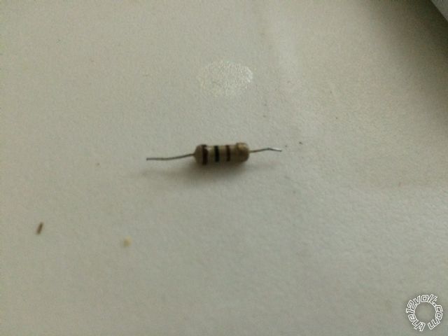
Posted By: howie ll
Date Posted: September 20, 2014 at 1:36 PM
Er no. No resistor.
For a third time use a meter and tell me your voltage between black and red at H1.
-------------
Amateurs assume, don't test and have problems; pros test first. I am not a free install service.
Read the installation manual, do a search here or online for your vehicle wiring before posting.
Posted By: wissam1981
Date Posted: September 20, 2014 at 1:54 PM
howie ll wrote:
Er no. No resistor.
For a third time use a meter and tell me your voltage between black and red at H1.
i already tell you in previous post, it's 13v
Posted By: catback
Date Posted: September 20, 2014 at 2:43 PM
Where/what is your ground location? A pic if you can.
13v is that with the car running or are you or your meter rounding up?
Posted By: wissam1981
Date Posted: September 20, 2014 at 3:03 PM
catback wrote:
Where/what is your ground location? A pic if you can.
13v is that with the car running or are you or your meter rounding up?
with car turn off, and used multimeter
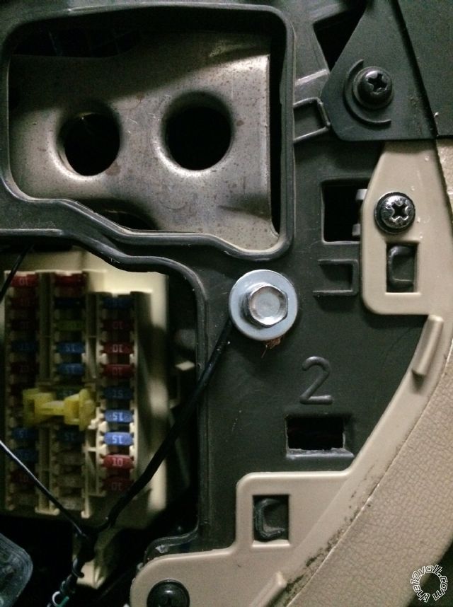
Posted By: catback
Date Posted: September 20, 2014 at 3:22 PM
That looks like a pretty weak ground. First off, if I'm not mistaken, that's plastic that the wire is resting on. Second, it looks like the bolt/washer is tightening down on the insulation instead of the wire. Third, you should have a ring terminal crimped/soldered on the end of that wire and bolt the ring terminal down instead of wrapping the wire around the bolt as you have done.
If you look around you may find a couple factory ground points or better places to attach your ground wire. Bare metal contact is the key to a solid ground.
Posted By: howie ll
Date Posted: September 20, 2014 at 4:11 PM
X 2 with Catback' The bolt might going through to metal but your wire is sitting on plastic. Never wrap wire around a bolt like that it will shake/vibrate loose.
-------------
Amateurs assume, don't test and have problems; pros test first. I am not a free install service.
Read the installation manual, do a search here or online for your vehicle wiring before posting.
Posted By: jgerard81
Date Posted: September 21, 2014 at 1:01 AM
When you connected the test light to ground out the black wire, it worked because the test light provided the system with a proper ground. It did not have anything to do with resistance through the test light. Once you relocate that ground wire, and use a ring terminal, you should be good to go.
Posted By: howie ll
Date Posted: September 21, 2014 at 1:08 AM
I use a test light to test every ground point, watch how bright the bulb glows.
And JGerard explained why.
-------------
Amateurs assume, don't test and have problems; pros test first. I am not a free install service.
Read the installation manual, do a search here or online for your vehicle wiring before posting.
Posted By: wissam1981
Date Posted: September 23, 2014 at 5:27 AM
I changed the Ground ( Black ) wire to multi locations ( car Body ), and still the same issue,
I even connect it to the Battery (-) directly with extra Wire.
Posted By: jgerard81
Date Posted: September 23, 2014 at 1:55 PM
Are you 100% sure you are plugging the GREEN/ blue harness into the correct port on the viper?
Posted By: howie ll
Date Posted: September 23, 2014 at 2:02 PM
Oh blimey mate too obvious?
-------------
Amateurs assume, don't test and have problems; pros test first. I am not a free install service.
Read the installation manual, do a search here or online for your vehicle wiring before posting.
Posted By: wissam1981
Date Posted: September 28, 2014 at 5:21 PM
i still have same problem guys,
i found this diagram for elantra 2010 doors lock.
https://jeffssalespage.com/sales/wp-content/uploads/2013/12/alarm-door-locks12.jpg
i'm wondering if this method will solve my issue ?
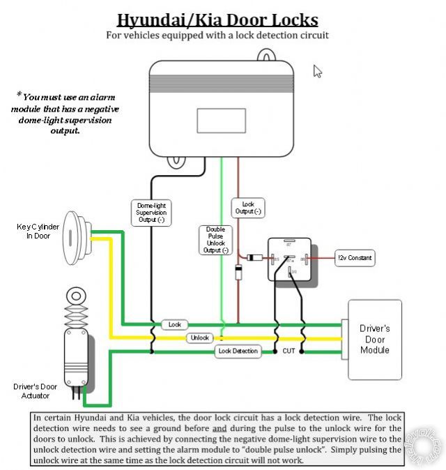
Posted By: catback
Date Posted: September 28, 2014 at 10:04 PM
Do the all the doors lock and unlock from the outside with the key? If so then yeah you can try that method. You can also try an earlier suggestion from jgerard81 where you use relays or a DEI 451m to control the lock wires and just have the 5706v control the relays/451m.
Posted By: wissam1981
Date Posted: September 29, 2014 at 4:12 AM
catback wrote:
Do the all the doors lock and unlock from the outside with the key?
what you mean?
Posted By: wissam1981
Date Posted: September 29, 2014 at 4:12 AM
catback wrote:
Do the all the doors lock and unlock from the outside with the key?
what you mean?
Posted By: howie ll
Date Posted: September 29, 2014 at 4:46 AM
Shut the doors use the key to lock and unlock.
-------------
Amateurs assume, don't test and have problems; pros test first. I am not a free install service.
Read the installation manual, do a search here or online for your vehicle wiring before posting.
Posted By: wissam1981
Date Posted: September 30, 2014 at 5:00 AM
howie ll wrote:
Shut the doors use the key to lock and unlock.
Yes I can
Posted By: wissam1981
Date Posted: September 30, 2014 at 5:00 AM
howie ll wrote:
Shut the doors use the key to lock and unlock.
Yes I can
|
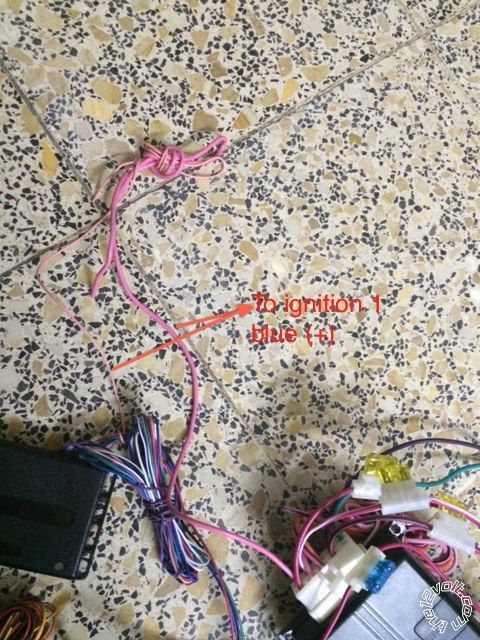
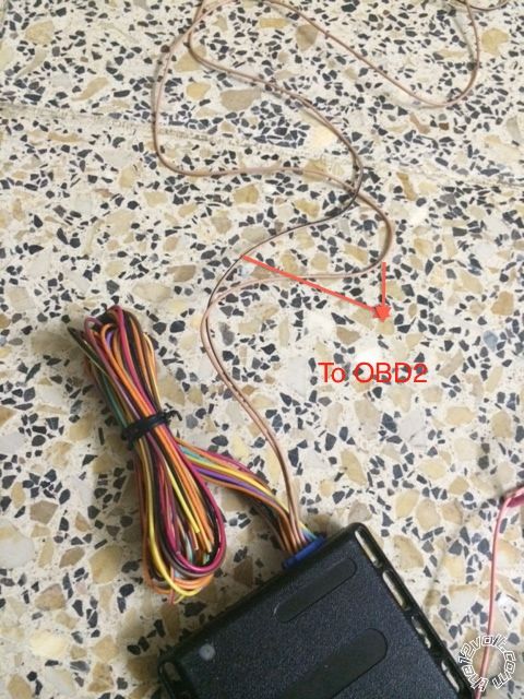
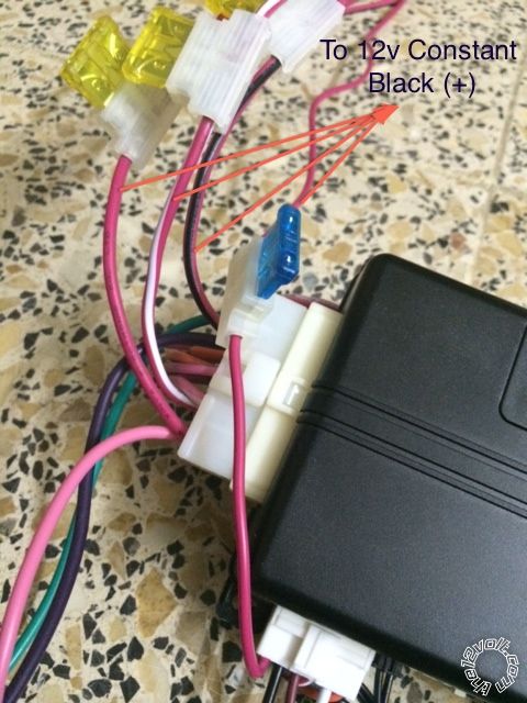
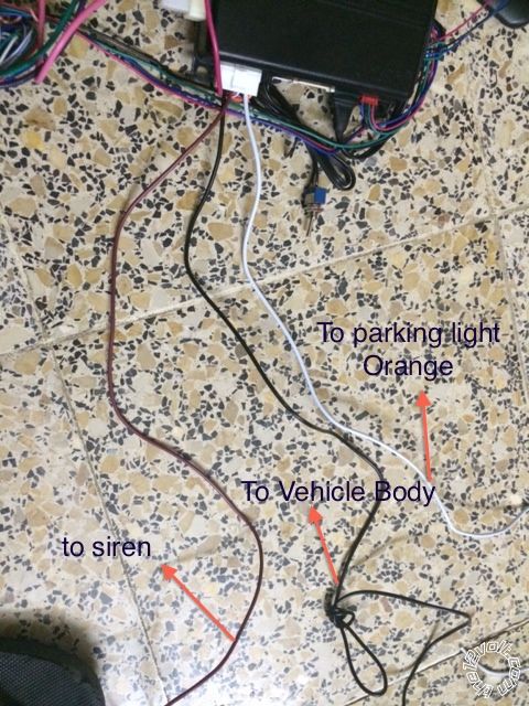
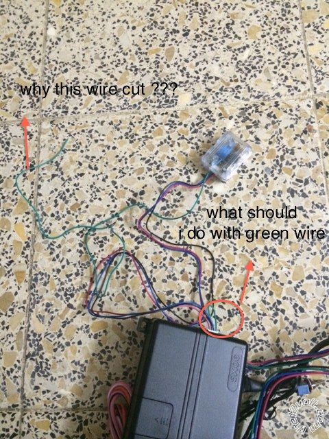
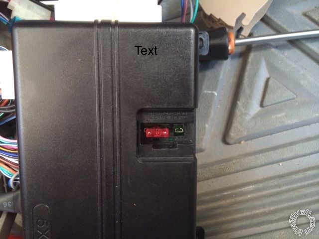
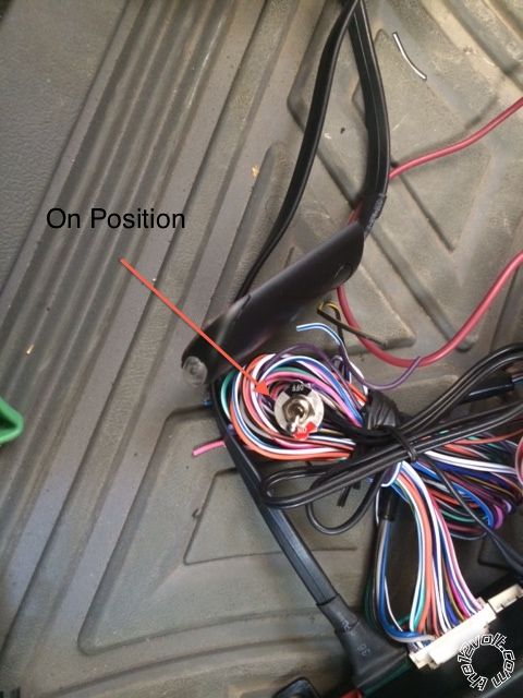
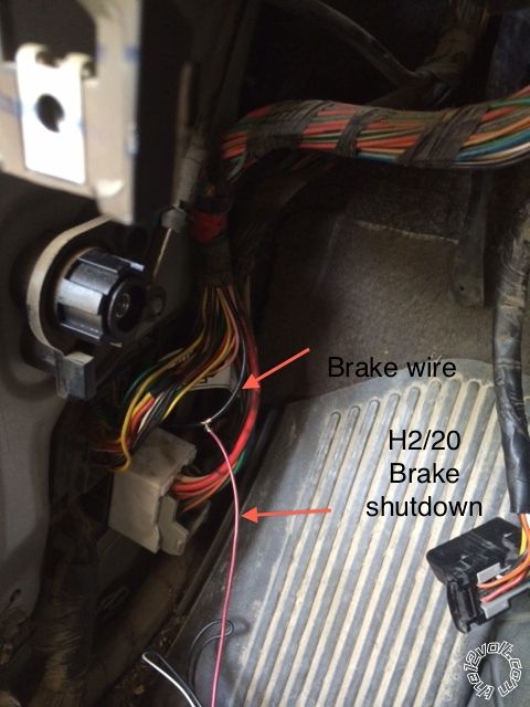
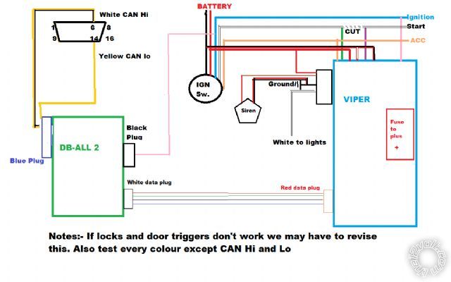