battery disconnect switch in car
Printed From: the12volt.com
Forum Name: Car Security and Convenience
Forum Discription: Car Alarms, Keyless Entries, Remote Starters, Immobilizer Bypasses, Sensors, Door Locks, Window Modules, Heated Mirrors, Heated Seats, etc.
URL: https://www.the12volt.com/installbay/forum_posts.asp?tid=137302
Printed Date: April 07, 2026 at 7:21 AM
Topic: battery disconnect switch in car
Posted By: pv13
Subject: battery disconnect switch in car
Date Posted: September 21, 2014 at 10:20 PM
My uncle recently purchased a "Battery Doctor/Mini Master disconnect switch with on-off knob for top or side post batteries" from Autozone, and wants to install it under his 1972 Chevelle dash.
Is this possible? I know these battery disconnects are meant to be installed close to the battery, but he has had a constant battery drain on the vehicle that no one has been able to fix, so he is trying to find a temporary solution that doesn't require opening up the hood every time he turns off the car.
I would appreciate any information I could get.
Thanks
Replies:
Posted By: catback
Date Posted: September 21, 2014 at 11:00 PM
Anything is possible but doing this is a very bad idea. Very heavy gauge would have to be run into the cabin of the car, a high amperage fuse or fusible link would have to be installed at the battery, and electrical performance would suffer from the extra length of cable and extra connection points. Meanwhile, there's more places for a high-current short to occur and possibly start a fire.
The inconvenience of opening the hood to operate a disconnect switch is far less than the inconvenience of a finely roasted '72 Chevelle. The best thing to do is find the battery drain, the electrical system on that car is quite basic so finding the parasitic drain shouldn't be too difficult.
Posted By: pv13
Date Posted: September 21, 2014 at 11:50 PM
Thanks for the reply. That is basically what I told him to do. He is going to be replacing all the electrical connections by next spring, so hopefully that will fix the problems he is having.
But just to clarify, the battery disconnect would be connected through the negative side of the battery. The installation scenario you described sounded like it would be connected through the positive. Right?
As far as I can tell the Chevelle has two main ground wires. The chassis ground (connected to the fender) and engine ground (connected to the bracket above the alternator). If I can't convince him to focus on the battery drain itself, the connections would be both ground wires on one post of the battery disconnect and the other post would be connected with a cable leading right to the negative of the battery. Correct?
Posted By: oldspark
Date Posted: September 22, 2014 at 1:18 AM
See newbie problem, engine kill switch where I discuss such issues.
I have never understood why people have used hot +12V isolation remote from the battery.
As to competitive sports that have not banned +12V isolation (in the cabin or remote vehicle corners)... what can I say?
Isolating the GND has none of the risks of hot cabling.
The battery GND (-ve) terminal connects to the isolation switch and all grounds are taken after the switch.
Posted By: pv13
Date Posted: September 22, 2014 at 1:59 AM
So how would I make the connections? One post on the switch would be connected to the negative post on the battery. What size cable should I use? The cable will pass through the firewall and be around 4 to 5ft.
The second post on the switch needs to have both chassis and engine ground. So would I connect the second post to ground inside the vehicle and, using the factory engine ground point, connect the engine ground to chassis ground in the engine bay? If that is correct, where is the best place to connect those wires? Would the firewall be good? Thanks
Posted By: oldspark
Date Posted: September 22, 2014 at 2:33 AM
The way I'd do it is chassis to engine in the engine bay, and battery to switch to chassis in the cabin.
Otherwise battery to switch & back out to the chassis.
Two cables from the output of the switch is undesirable.
You can have multiple cables from the chassis to the engine, or gearbox etc. (I usually run 2 or more in case one fails.)
IMO firewalls are not good - they're too thin.
The cable has to be heavy enough to not cause excessive voltage drop nor cable heat during cranking. Normal cable current with engine running is far less than cranking, in fact it should only be the battery recharge current.
If the existing cable from battery to starter ground (engine) has been sized to a minimum, then the new cable will have to be n times its copper cross section where n is the the length of the new cable compared to the old - ie, n times longer.
However the existing starter ground cable may be heavier than is needed.
The minimum gauge can also be calculated if you know the length and the starter motor current and the max voltage drop it can have (taking into account the +12V cable drop, plus connections).
Posted By: howie ll
Date Posted: September 22, 2014 at 2:38 AM
This is a really bad idea, find the drain first, probably a door switch for dome light, glovebox light or trunk light switch.
Any isolator switch must be at the battery AND at the negative side for safety reasons.
-------------
Amateurs assume, don't test and have problems; pros test first. I am not a free install service.
Read the installation manual, do a search here or online for your vehicle wiring before posting.
Posted By: oldspark
Date Posted: September 22, 2014 at 4:30 AM
Hmmm... now that I read the full OP...
I agree that it is a bad idea to fit an isolation switch to overcome a battery drain. Find the drain. Maybe it's a failing alternator diode or other component or wiring failure which will eventually burn the car to the ground.
And I assume disconnecting the battery is known to work - ie, it's not a failing battery.
Isolation switches are only fitted for vehicles are rarely used, or competition and maybe oft worked on vehicles - the latter 2 requiring disconnection of the vehicle-battery ground.
As for safety, it is not unsafe to isolate GND wrt shorts etc (and you may have picked up how stupidly moronic I consider hot-side isolation in cabins etc to be!) EXCLUDING the damage or stalling that could occur due to the longer cable - ie, longer the cable, the greater the risk of failures. But AFAIAK, the latter risk has not resulted in a 3rd ground being fitted to OEM vehicles - it is still common to only have 2 cables to join battery GND & chassis/body & engine/alternator without the 3rd "redundant" cable.
Posted By: pv13
Date Posted: September 22, 2014 at 4:39 AM
oldspark wrote:
The way I'd do it is chassis to engine in the engine bay, and battery to switch to chassis in the cabin.
Otherwise battery to switch & back out to the chassis.
Two cables from the output of the switch is undesirable.
You can have multiple cables from the chassis to the engine, or gearbox etc. (I usually run 2 or more in case one fails.)
IMO firewalls are not good - they're too thin.
The cable has to be heavy enough to not cause excessive voltage drop nor cable heat during cranking. Normal cable current with engine running is far less than cranking, in fact it should only be the battery recharge current.
If the existing cable from battery to starter ground (engine) has been sized to a minimum, then the new cable will have to be n times its copper cross section where n is the the length of the new cable compared to the old - ie, n times longer.
However the existing starter ground cable may be heavier than is needed.
The minimum gauge can also be calculated if you know the length and the starter motor current and the max voltage drop it can have (taking into account the +12V cable drop, plus connections).
Thanks for the input. If he is dead set on doing this, I will recommend that he upgrade his cables to 2 or 0 gauge Stinger wire. And because of that, I think only one wire will go through the firewall. Leaving chassis ground connection in the cab, and engine ground connection(s) in the engine bay.
So the best kind of ground would be a direct connection to the actual chassis?
Posted By: pv13
Date Posted: September 22, 2014 at 4:51 AM
Thanks for your responses. I agree with both of you. The drain should be the priority. He took it to his local mechanic, and the only thing they could supposedly find putting a drain on the battery was a gps smart tracker. Obviously, it has to be on all the time, but the manufacturer claims a continuous amp draw of only 50mA. That shouldn't be enough to drain overnight. Right?
Posted By: oldspark
Date Posted: September 22, 2014 at 5:24 AM
50mA IMO is a bit high.
I had an Alpine that drained ~120mA and that was only a problem after 3-4 days, and that's with a smallish battery (~40AH). My other drains are under 10mA.
Maybe the battery is old or has lost capacity. That's often the cause of such problems.
Of course draining a battery that quick is a problem. I'd steel the vehicles after it's been sitting for a day...
Of course now I know it'll have an isolator I can steel it anytime.
I bond to chassis because my vehicles are either of monocoque design with reasonable rail gauges here & there, else proper chassis frames.
Even if monocoque did involve heavy metal gauges, their electrical bonding should be quite good so it's a matter of having a big enough connection area.
I maintain that chassis and bodies conduct better than cables, but I have heard stories where apparently there is insufficient bonding & conduction due to insufficient spot welds or excessive corrosion. And of course non-metallic panels and glues will not conduct!
Some claim a mere 16G panel is insufficient for cranking and big amplifier etc currents but they don't seem to take panel width into account. Then again, some steels only have 6% the electrical conductivity of copper.
The simple test is to measure voltage drops during operation or cranking. If battery- to starter case is (say) only 1V, fine. If it's too high, do various measurements to see where the drop occurs.
Posted By: catback
Date Posted: September 22, 2014 at 9:42 AM
If your uncle installs a battery disconnect to kill parasitic draws, there goes his gps tracker.
As for needing larger cable than factory, it's almost a requirement because of the much longer run - battery to switch and back.
If the only drain found is a gps tracker, he should have his battery tested they do go bad on weekend fair weather drivers as commonly if not more commonly than daily drivers.
Posted By: pv13
Date Posted: September 22, 2014 at 1:04 PM
This chevelle has been a project car for the past two and a half years. He has replaced the floor, but this car sat in western Washington state for many years, so there is no telling how much rust is hiding until he takes it apart. That is what worries me about the reliability of his electrical connections, especially further back in the vehicle.
Thank you all for your help and advice. If he still wants the switch, I'll convince him to keep it next to the battery. But he needs to find the drain. The problem is that I don't have a Digital multimeter with the capabilities to measure amp draw, and the local mechanics don't seem to know a great deal about testing voltage drops, resistance, or current. I'm pretty sure they initially claimed the gps tracker was at fault because that is the only accessory item installed in the car :).
So I will have to track down a mechanic who knows what they're doing.
Thanks again.
Posted By: pv13
Date Posted: September 22, 2014 at 1:15 PM
catback wrote:
If your uncle installs a battery disconnect to kill parasitic draws, there goes his gps tracker.
As for needing larger cable than factory, it's almost a requirement because of the much longer run - battery to switch and back.
If the only drain found is a gps tracker, he should have his battery tested they do go bad on weekend fair weather drivers as commonly if not more commonly than daily drivers.
Thanks for your input. Yeah, the whole point of the gps tracker is to constantly track the vehicle. But if he is taking off his negative and removing power from the tracker, it no longer functions. I have explained this to him several times :)
He replaced the battery, alternator, external voltage regulator, and corresponding cables, but still had a drain on the battery.
He needs to find a reliable mechanic who truly knows how to test vehicle electrical systems, and approach the problem analytically. Moving throughout the charging system measuring each part, cable, and connection, and determining whether they are "good" or not.
Thanks again
Posted By: howie ll
Date Posted: September 22, 2014 at 2:14 PM
It ain't the tracker!
The units I install in the UK draw 3 milliamps except when sending and receiving on command.
-------------
Amateurs assume, don't test and have problems; pros test first. I am not a free install service.
Read the installation manual, do a search here or online for your vehicle wiring before posting.
Posted By: Ween
Date Posted: September 22, 2014 at 6:45 PM
Is there a Menards or Home Depot near you? Both have multimeters, inexpensive units that will measure current.
Is the fuse box under the dash the original one (with glass fuses?) or has it been upgraded? The original only has four fuses and circuit breakers for the battery draw circuits, granted they do supply multiple items.The multimeter (in ammeter mode) connected in series on the battery or ground cable will show the current draw (50mA or so). Disconnect the tracker, check draw. Remove the fuses one at a time (for the battery supplied circuits) noting draw.
The courtesy/dome light circuit might be tricky as you'll need the door open to access the fuse box easier. If the bulbs are accessible, remove them first. ..then the fuse. When the current draw drops to minimal (10mA or less), the offending circuit should be identified. Battery circuits under the hood to disconnect would be the alternator, voltage regulator (if present), horn relay (may have key buzzer built in) assuming the draw hasn't been found.
Hope this helps.
Mark
Posted By: pv13
Date Posted: September 22, 2014 at 7:05 PM
Ween] wrote:
Is there a Menards or Home Depot near you? Both have multimeters, inexpensive units that will measure current.
Is the fuse box under the dash the original one (with glass fuses?) or has it been upgraded? The original only has four fuses and circuit breakers for the battery draw circuits, granted they do supply multiple items.The multimeter (in ammeter mode) connected in series on the battery or ground cable will show the current draw (50mA or so). Disconnect the tracker, check draw. Remove the fuses one at a time (for the battery supplied circuits) noting draw.
The courtesy/dome light circuit might be tricky as you'll need the door open to access the fuse box easier. If the bulbs are accessible, remove them first. ..then the fuse. When the current draw drops to minimal (10mA or less), the offending circuit should be identified. Battery circuits under the hood to disconnect would be the alternator, voltage regulator (if present), horn relay (may have key buzzer built in) assuming the draw hasn't been found.
Hope this helps.
Mark
Thank you Mark. That does help. I told him to do a parasitic draw test in the past, but for some reason it never got done. He is going to be taking the car to his mechanic soon, and I will definitely pass on your suggestions. Thanks again
Posted By: oldspark
Date Posted: September 23, 2014 at 3:20 AM
Of course if it is the tracker, put a switch on that & forget battery isolation.
And FWIW, when he has problems with the alternator or regulator, replace them with a modern alternator with integral regulator. They are far superior and overcome various problems with external regulators. I suggest 2-wire types ie with S&L "small" wires - namely Sense (which goes direct to the battery + terminal) and chargeLamp which goes to the dash charge lamp (and electric fuel pump and dual-battery isolator relays etc). You merely connect the L terminal to the original regulator's chargeLight output and run a (thin) wire from S to batt+ (which can be fused tho preferably the wire is thin enough to be its own fuse).
Posted By: pv13
Date Posted: September 23, 2014 at 3:23 AM
oldspark wrote:
Of course if it is the tracker, put a switch on that & forget battery isolation.
And FWIW, when he has problems with the alternator or regulator, replace them with a modern alternator with integral regulator. They are far superior and overcome various problems with external regulators. I suggest 2-wire types ie with S&L "small" wires - namely Sense (which goes direct to the battery + terminal) and chargeLamp which goes to the dash charge lamp (and electric fuel pump and dual-battery isolator relays etc). You merely connect the L terminal to the original regulator's chargeLight output and run a (thin) wire from S to batt+ (which can be fused tho preferably the wire is thin enough to be its own fuse).
That's a good point. I'll make sure to pass on the advice. Thanks
Posted By: yellow_cake
Date Posted: September 24, 2014 at 3:50 AM
If you go on youtube, search for parasitic battery drain by EricTheCarGuy, that video in my opi nion is very helpfu.
Posted By: pv13
Date Posted: September 24, 2014 at 5:29 PM
yellow_cake wrote:
If you go on youtube, search for parasitic battery drain by EricTheCarGuy, that video in my opi nion is very helpfu.
It is very helpful! I saw that video months ago, and it was the way I told my uncle to find the drain. But he seemed to opt for something different :). We've both been really busy recently, but I'm still trying to convince him to forget about the switch and focus on the drain. Thanks
Posted By: davep.
Date Posted: September 26, 2014 at 8:47 PM
I'm very familiar with 68-72 Chevelles. I've owned my 70 El Camino for 41 years, and worked on tons of these cars over the years. A few comments /observations.
50ma is a 1.2 amp hour per day draw. A group 75 battery has at minimum a 50amp hour capacity at that minimal rate of discharge. You should be able to crank the car weeks later with a 50ma draw. It isn't the tracker.
If you do the cut-off switch in the negative wire, changing to a gear reduction mini starter (I specify a 1996, 454 7.4L Silverado pick up for the one I use) will reduce the amp draw of the starter that #4 wire will be more than adequate to crank the "mini" starter even with the 8' or so of added circuit run.
What alternator / regulator is in the 72? 1972 was the last year for the 10si Delco with divorced regulator mounted on the fender. Sometimes the old mechanical regulators would stick on. But 40 years later the original regulator has probably been changed out to an electronic unit which doesn't suffer this maladie.
\
In 73 they introduced the 12si with the internal regulator. I've seen some late 72's with 12si alternators. Early 12si's were notorious for regulator failures that kept the alternator on without the engine running. This will drain the battery overnight, as rotor draw is about 5 amps.
A quick test for alternator remaining "on" after engine stop is to take a steel screwdriver and touch it to the shaft in the center of the pulley nut. If the screwdriver "sticks" with magnetism, the field is energized, and is the source of battery draw.
Check the alternator.
It's not the tracker.
It could be a weak battery.
Use a mini starter if you want to keep cable size smaller, and do the shut-off.
Regards
Posted By: catback
Date Posted: September 27, 2014 at 10:58 AM
How hard is it to fix a battery drain when 8' of ground cable, a battery disconnect switch, AND a new mini-starter is the easier thing to do? sheesh 
Posted By: howie ll
Date Posted: September 27, 2014 at 11:24 AM
About 20 minutes with a 12Volt test light?
(Keep it simple).
-------------
Amateurs assume, don't test and have problems; pros test first. I am not a free install service.
Read the installation manual, do a search here or online for your vehicle wiring before posting.
Posted By: pv13
Date Posted: September 28, 2014 at 2:45 PM
davep. wrote:
I'm very familiar with 68-72 Chevelles. I've owned my 70 El Camino for 41 years, and worked on tons of these cars over the years. A few comments /observations.
50ma is a 1.2 amp hour per day draw. A group 75 battery has at minimum a 50amp hour capacity at that minimal rate of discharge. You should be able to crank the car weeks later with a 50ma draw. It isn't the tracker.
If you do the cut-off switch in the negative wire, changing to a gear reduction mini starter (I specify a 1996, 454 7.4L Silverado pick up for the one I use) will reduce the amp draw of the starter that #4 wire will be more than adequate to crank the "mini" starter even with the 8' or so of added circuit run.
What alternator / regulator is in the 72? 1972 was the last year for the 10si Delco with divorced regulator mounted on the fender. Sometimes the old mechanical regulators would stick on. But 40 years later the original regulator has probably been changed out to an electronic unit which doesn't suffer this maladie.
\
In 73 they introduced the 12si with the internal regulator. I've seen some late 72's with 12si alternators. Early 12si's were notorious for regulator failures that kept the alternator on without the engine running. This will drain the battery overnight, as rotor draw is about 5 amps.
A quick test for alternator remaining "on" after engine stop is to take a steel screwdriver and touch it to the shaft in the center of the pulley nut. If the screwdriver "sticks" with magnetism, the field is energized, and is the source of battery draw.
Check the alternator.
It's not the tracker.
It could be a weak battery.
Use a mini starter if you want to keep cable size smaller, and do the shut-off.
Regards
He bought the alternator (with the external regulator in the fender) and battery at the same time. So I will definitely have him check out the alternator. I convinced him to focus on the drain, so the switch is no longer necessary. Thanks
Posted By: oldspark
Date Posted: September 28, 2014 at 6:40 PM
Tho it sounds like this thread is over & solved...
pv13]H wrote:
bought the alternator (with the external regulator ...
So just the alternator, or the regulator as well?
Not that I think that's the problem - tho if it is it will be easy to find - but someone once said...
uncredited KIA wrote:
... when he has problems with the alternator or regulator, replace them with a modern alternator with integral regulator...
But it sounds like YOU have the right ideas. He needs to pull his finger out and do some basic checking.
If it's a laziness issue, as per catback - finding (or isolating) a drain is more work than installing a high current battery feed switch? (BTW - the attraction of reduction starters is irrelevant to polarities etc.)
If it's a thinking issue - good luck - but to isolate the battery and hence alarms & HU memories etc when the culprit was (supposedly) known... Surely you'd merely isolate the culprit? (In fact IMO if it is the tracker - remove it unless its for family to track the driver. Why have it otherwise?)
Posted By: oldspark
Date Posted: September 28, 2014 at 7:21 PM
And since this thread seems over (I'm tempted to make this reply a new thread...)
A few days ago I dropped in on a competitive mate who I hadn't seen for several years.
I asked if he was using - or if The Regulators - were prescribing multipole switches like the FIA approved Battery Isolator Switch when "engine kill" and "battery isolation" functions were combined.
What horrified me is that remote +12V isolation is still acceptable.
What amused me (with horror) was the other 2 things my mate said:
- various (complex?) arrangements use relays; &
- scrutineers don't care how the thing(s) work as long as when they flip the switch, the battery is isolated and the engine dies.
So yet again we can have a "safety feature" that kills you in the field but that's ok since it passed (static) tests.
Apologies, but I am simply amazed. We have devolved at least 30 years. What next - red EXIT signs in buildings (because that's logical? and ban laminated windscreens & airbag systems?
But I'll leave all that for the first victims to take action...
I was going to add that that is why I avoid Australian forums, however after seeing the wiring diagrams for the FIA approved switch (which all isolate the +12V batter terminal) I'm wondering if the rest of the world is turning stupid, or ignorant?
BTW - the IMO correct base diagram WRT heavy isolation wiring in the GND path ... 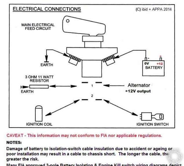
Posted By: pv13
Date Posted: September 30, 2014 at 4:31 PM
pv13] wrote:
davep. wrote:
I'm very familiar with 68-72 Chevelles. I've owned my 70 El Camino for 41 years, and worked on tons of these cars over the years. A few comments /observations.
50ma is a 1.2 amp hour per day draw. A group 75 battery has at minimum a 50amp hour capacity at that minimal rate of discharge. You should be able to crank the car weeks later with a 50ma draw. It isn't the tracker.
If you do the cut-off switch in the negative wire, changing to a gear reduction mini starter (I specify a 1996, 454 7.4L Silverado pick up for the one I use) will reduce the amp draw of the starter that #4 wire will be more than adequate to crank the "mini" starter even with the 8' or so of added circuit run.
What alternator / regulator is in the 72? 1972 was the last year for the 10si Delco with divorced regulator mounted on the fender. Sometimes the old mechanical regulators would stick on. But 40 years later the original regulator has probably been changed out to an electronic unit which doesn't suffer this maladie.
\
In 73 they introduced the 12si with the internal regulator. I've seen some late 72's with 12si alternators. Early 12si's were notorious for regulator failures that kept the alternator on without the engine running. This will drain the battery overnight, as rotor draw is about 5 amps.
A quick test for alternator remaining "on" after engine stop is to take a steel screwdriver and touch it to the shaft in the center of the pulley nut. If the screwdriver "sticks" with magnetism, the field is energized, and is the source of battery draw.
Check the alternator.
It's not the tracker.
It could be a weak battery.
Use a mini starter if you want to keep cable size smaller, and do the shut-off.
Regards
He bought the alternator (with the external regulator in the fender) and battery at the same time. So I will definitely have him check out the alternator. I convinced him to focus on the drain, so the switch is no longer necessary. Thanks
I took a steel screwdriver to the alternator like you said, and while there wasn't a strong magnetic connection, you could definitely feel the magnetic force between the two when the car had been sitting for two weeks.
Does this mean the alternator or external regulator is faulty? He had a problem with the drain before he replaced these parts.
I sent you a private message, as this is no longer about the battery disconnect switch.
Thanks.
Posted By: oldspark
Date Posted: September 30, 2014 at 4:49 PM
Many alternators will have residual magnetism - that's why sometimes certain types start without the trickle/tickle D+/L feed.
A strong pull indicates rotor current (or permanent magnets).
A weak pull may exist with no rotor current.
And not all leakages go thru the rotor.
The magnet test is a simple test to indicate high rotor current or residual magnetism.
It is not a "current drain" test.
Posted By: pv13
Date Posted: September 30, 2014 at 5:58 PM
oldspark wrote:
Many alternators will have residual magnetism - that's why sometimes certain types start without the trickle/tickle D+/L feed.
A strong pull indicates rotor current (or permanent magnets).
A weak pull may exist with no rotor current.
And not all leakages go thru the rotor.
The magnet test is a simple test to indicate high rotor current or residual magnetism.
It is not a "current drain" test.
Okay thanks. Given that he had the same drain before he replaced the alternator,external regulator, and battery, it is probably something like residual magnetism. Thanks
Posted By: howie ll
Date Posted: September 30, 2014 at 6:22 PM
Good lord simply use, borrow or find a DMM with a 10amp DC current rating, disconnect the NEG terminal and place he NEG or black lead to the battery terminal, the POS or red lead to the loose lead, after setting up the meter to read 10amps current.
Then start disconnecting alternator feed and and removing removing fuses one at a time.
Trunk light?
Glovebox light?
Bet you can't even get a reading for the tracker on the 10amp scale.
-------------
Amateurs assume, don't test and have problems; pros test first. I am not a free install service.
Read the installation manual, do a search here or online for your vehicle wiring before posting.
Posted By: oldspark
Date Posted: October 01, 2014 at 7:43 PM
x2.
This thread should have run its course. Four pages for something that is a typical procedure - test (DMM measure) and eliminate or trace until the problem is found.
Incidentally, on the residual magnetism, essentially all electro-mag rotor alternators should exhibit that unless they have aluminium or non-ferric main shafts (not that I know of any for automobiles).
It's a question of how much. Hence as I said it's merely a "positive confirmation" test - ie, confirms the existence of a highish rotor current but does not rule out anything else.
And since I often magnetise my screwdrivers with sharp knock(s) whilst oriented north-south I question the validity of any (weak) magnetic test. (LOL - those Mythbuster ignorami had to use a battery & wire to magnetise the ferro in their compass! Yep, they were as useful as ever.)
|