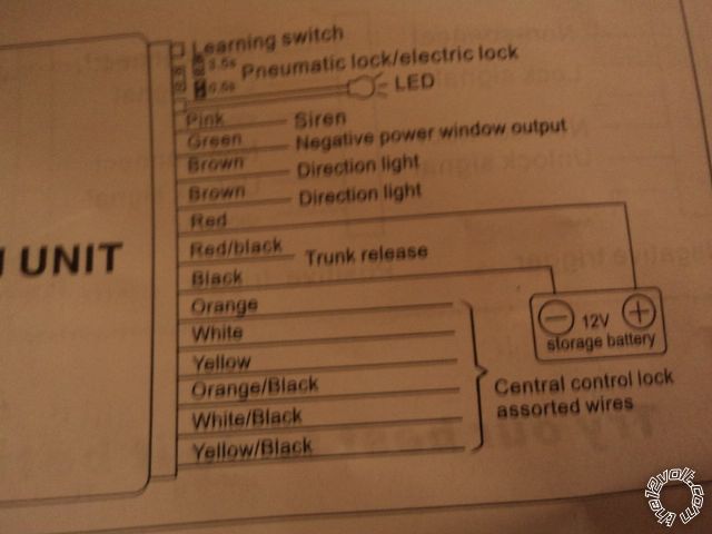
I bought a cheap keyless entry kit online, and cant get my doors to unlock/lock with the system. I wired my parking lights to work, and they activate when I click the remote, and I hear relays clicking, but nothing happens to my doors. I believe I set it up as a Negative trigger. I am still confused about what wires to officially connect the lock and unlock wires from the system to. It seems like every forum/ website/ post has a different method of using different wires. I have tried many of them, and still no luck. The connections from the back of the system, in order are:
Pink: Siren
Green: Negative window output
Brown: direction light
Brown: direction light
Red: 12V
BLACK/ red: trunk release
Black: ground
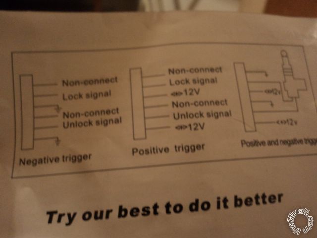
Now the second part of the system differs if you set it up as a negative/positive or dual triggers.
With the Negative trigger set up:
Orange: non-connect
white: lock signal
yellow: ground
ORANGE / black: non-connect
WHITE/ black: unlock signal
yellow/black: ground
What I have done is taken the yellow and yellow/black, and connected them together, and spliced them on to the system ground (black) wire, so essentially there is just one ground wire for the whole system.
The white lock wire and WHITE/ black unlock wire have been connected to numerous combinations of different colored wires, with still not result. I am wondering if i am missing something. Should I ground the orange and ORANGE / black too? or give them 12v? I am at a lose :( any help would be fantastic!
The Keyless entry wiring diagrams:

Other image got cut off, here it is:
Your 1993 Camry has Type B power locks. Your RKE system wiring setup is correct. Basically, it's just 2 internal
relays that are wired up to provide the correct output for whatever type system your car has ( Type A, B, C, etc ).
Lock internal relay:
Orange ( Pin 87a ) : non-connect
White ( Pin 30 ) : lock signal ( output )
Yellow ( Pin 87 ) : ground ( input )
Unlock internal relay:
ORANGE / Black ( Pin 87a ) : non-connect
WHITE/ Black ( Pin 30 ) : unlock signal ( output )
Yellow/Black ( Pin 87 ): ground ( input )
So, for your 1993 Camry application, the Yellow and Yellow/Black source/input wires are connected to Chassis
Ground. The Orange and ORANGE / Black wires are not used and should be insulated. The White and WHITE/ Black
output wires are connected to these wires in your Camry :
POWER LOCK BLUE/WHITE (TYPE B) IN PASSENGER KICK PANEL, BLUE PLUG
POWER UNLOCK LIGHT GREEN/ RED (TYPE B) IN PASSENGER KICK PANEL, BLUE PLUG
If you don't have a computer safe LED test probe, you can use a Digital Multi Meter to test for these wires. Set
the DMM to 20V DC, connect the Red test lead to a +12V constant source and the Black test lead to the suspect
wire. When you press the corresponding lock button on the passenger door panel switch, the DMM should go
to +12V. If I remember, the Blue Plug in the passenger kick panel is pretty easy to find and access. If you have
positioned the RKE system under the drivers side dash panel, you might have to extend/lengthen the two wires
so they reach the PKP area. All these connections should be well soldered and properly insulated for best
durability and reliable operation.
-------------
Soldering is fun!
Thanks kreg! I was able to successfully wire the system. Appreciate your help!