So i just installed my first remote starter in a while and i was wondering if someone could upgrade me on some theory that i'm not understanding. This is sort of a 3 part question.
I have a vehicle with 2 starter wires and the unit i bought (bulldog RS82b) basically tells me to just hook the output of the module up to both starter wires.
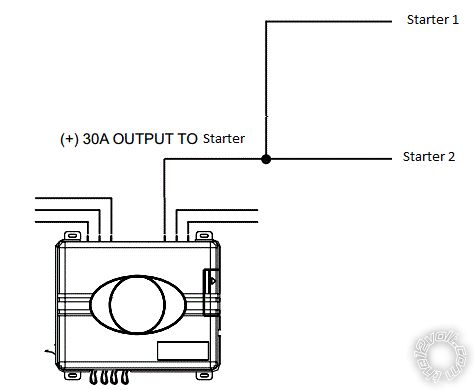
Now i have read several threads on this site that tell me the above is a terrible idea and that this is a more appropriate install.
Question #1 - If the current draw of both starter wires is within the capacity of the installed relay in the remote starter why is it not ok to do what is shown in the first picture?
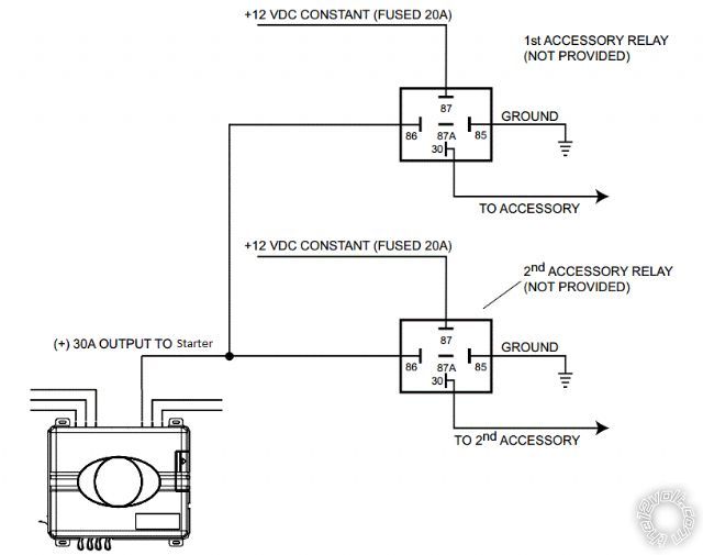
Question #2 - Assuming the first picture is bad why wouldn't you just install it like this since the unit is certainly designed to at least handle one of the wires.
Question #3 - Most cars (including mine) only have one 12v constant wire that all of this power is being tapped from. Do most people use this wire to tap off all of these extra relays or are some people running a completely separate line from the battery? Just curious what everyone else does because this is the only one that has ever seems weird to me during installs because you can have 3 or 4 connections coming off this one 12v constant wire.
I'm chomping at the bit to hear responses to these questions.
Just my thoughts as a silly lay reader (I'm not an installer etc).
If you have a 30A capable output, why instead use 1 or 2 relays each limited to 20A?
Else why not use a 40A or 60A relay etc and maybe split the feed & fuse?
IE - the centre diagram seems stupid per se but may have been appropriate for a specific install.
Of course it might be the use of relays instead of high current diodes to prevent interconnection when not being powered...
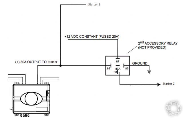
The bottom pic is in keeping with what I said above - ie, keeping the original 30A capability and extending an additional 20A.
I doubt that any typical constant +12V feed handles 20A or 50A etc without voltage drop or blowing a fuse - except where that feed is off the battery or after some master flink.
IMO it's the usual rule. If it's a low power feed, run it from anywhere. If it's high current - or you want the best or cleanest voltage - run your own fused feed from the battery etc; via a relay if needed.
The first diagram is usually a no-no, you don't permanently join two separate and possibly isolated circuits circuits together. If they are separated, they were separated for a reason.
Out of the three diagrams #2 is the best of the three, reason being #1 is obviously bad for reasons above and #3 is not that great because the relay activates during both remote start and regular key use. Utilizing the ground while running output with diagram #3 would rectify the downfall of #3 and make it the ideal setup as it only would require one relay.
The power feed feeding the ignition switch is all you need to feed the ignition wires. It's capable enough when the ignition switch is doing the connecting/switching, no reason why it wouldn't be enough with the remote starter doing the connecting/switching.
Assuming no low current NEG (-) starter output on this unit to drive a relay, the second diagram is also correct for starter also but in both cases fuse each relay at 30 amps, AFAIK all Bosch/Tycho cubes are 30 amp rated across the contacts.
-------------
Amateurs assume, don't test and have problems; pros test first. I am not a free install service.
Read the installation manual, do a search here or online for your vehicle wiring before posting.