07 town & country
Printed From: the12volt.com
Forum Name: Car Security and Convenience
Forum Discription: Car Alarms, Keyless Entries, Remote Starters, Immobilizer Bypasses, Sensors, Door Locks, Window Modules, Heated Mirrors, Heated Seats, etc.
URL: https://www.the12volt.com/installbay/forum_posts.asp?tid=137607
Printed Date: May 13, 2026 at 10:06 PM
Topic: 07 town & country
Posted By: oleg4
Subject: 07 town & country
Date Posted: November 05, 2014 at 7:22 PM
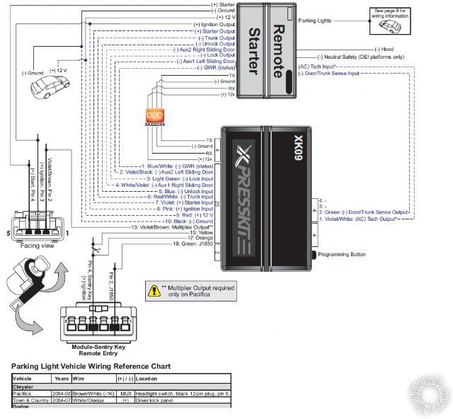
I am installing a 2 way viper alarm with remote starter, using a XK09 for bypass.
Got most of the wiring done, but got stuck with the parking light.
Need help finding the wire.
Thanks
Replies:
Posted By: oleg4
Date Posted: November 05, 2014 at 7:25 PM
it is a 07 chrysler town & country touring 3.8l
Posted By: smokeman1
Date Posted: November 05, 2014 at 8:01 PM
The DBall instructions lists it as WHITE/ Orange (+) in drivers kick panel.
https://www.bulldogsecurity.com/bdnew/vehiclewiringdiagrams.aspx
Bulldog list two positive wires in drivers kick panel as well as a Negative wire at the headlight switch
-------------
When all else fails, Read the Instructions
Support the12volt.com Make a Donation
Posted By: kreg357
Date Posted: November 05, 2014 at 8:16 PM
As Mr. Smoke says...
Being as the T&C is similar to the Dodge Caravan, look up the Caravan at Bulldog Security. They have a very complete write up with a bunch of photos and relay diagrams. Should make finding the wire easier. I always go with the WHITE/ Brown (-) wire @ the Headlight Switch using a 2K Ohm 1/2 watt resistor. ------------- Soldering is fun!
Posted By: oleg4
Date Posted: November 05, 2014 at 8:51 PM
Thanks a lot guys, will look for it tomorrow.
Posted By: smokeman1
Date Posted: November 05, 2014 at 9:17 PM
Excellent call on the Caravan Kreg. I always forget about the similar make/model versions.
-------------
When all else fails, Read the Instructions
Support the12volt.com Make a Donation
Posted By: oleg4
Date Posted: November 07, 2014 at 10:01 AM
Also is their a way that I could tap to tech wire inside the car instead of going to the coil
Posted By: kreg357
Date Posted: November 07, 2014 at 10:14 AM
The XK09 flashed with 9.Chrysler V3.02 firmware should supply Tach signal. On some DEI remote starter's it will
not supply the Tach signal via D2D, so you might have to hardwire the connection. ( XK09 4 Pin Plug, Violet/White
to R/S Tach input wire.)
I've found the firewall pass through pretty convenient on those vehicles and the coil pack produces a good Tach
signal. On the 3.3L and 3.8L, use the BLUE/GREEN, BLUE/TAN or BLUE/ORANGE wire at the coil pack.
------------- Soldering is fun!
Posted By: oleg4
Date Posted: November 07, 2014 at 5:55 PM
thx for the reply,
everything works accept in dose not crank when i hit the starting button.
i
also installed
DEI 520T BACKUP BATTERY
and
XK09 BYPass
Tech signal is programed
Transmission mode is in automatic.
when i run remote start shutdown/start up diagnostics
diagnostic
it told
low or no rpm
timer mode/turbo mode/ manual mode
low battery (voltage mode)
here is what i wire to
Main Harness 6pin
h1/1 red const 12v - ------ --- --- --- --- tap to a const 12v TN/WH BCM
h1/2 black grnd ----------------- ---- --- -- -- chassis ground Bk BCM
h1/3 brown siren out - -- - - ----------- --- connect to sirens red (black to ground)
h1/4 WHITE/ brown park light isolation wire ------- not used
h1/5 white park light out - -------------------- WHITE/ BROWN at head light switch
h1/6 orange ground when armed out -------------- Not used
Door lock 3 in
1 blue out - not used
2 empty
3 green - not used
Aux/shutdown/trigger harness, 24-pin connector
1 PNK/WHITE (-) 200mA Ignition 2/Flex OUTPUT - - - - - - - - Not used
2 BLUE/WHITE (-) 200mA 2ND STATUS /REAR DEFOGGER OUTPUT- - - - - - Not used
3 RED / WHITE (-) 200mA TRUNK RELEASE OUTPUT- - - - - - - - - Not used
4 BLACK / YELLOW (-) 200mA DOME LIGHT OUTPUT- - - - - - - - - - Not used
5 DARK BLUE (-) 200mA STATUS OUTPUT- - - - - - - - - - - - - - Not used
6 WHITE/ BLACK (-) 200mA AUX 3 OUTPUT- - - - - - - - - - - - Not used
7 WHITE/ VIOLET (-) 200mA AUX 1 OUTPUT- - - - - - - - - Not used
8 ORANGE / BLACK (-) 200mA AUX 4 OUTPUT- - - --- - Not used
9 GRAY (-) HOOD PIN INPUT (NC OR NO) - - - - - --- - - - -Hood pin
10 BLUE (-) TRUNK PIN/INSTANT TRIGGER INPUT (N/C OR N/O)- - - - Not used
11 WHITE/ BLUE ACTIVATION INPUT - - - - - - Not used
12 VIOLET/WHITE* TACHOMETER INPUT - - - - - Not used
13 BLACK/ WHITE** (-) NEUTRAL SAFETY /PARKING BRAKE INPUT - - - - - - Ground
14 GREEN/ BLACK (-) 200mA FACTORY ALARM DISARM OUTPUT- - - - - Not used
15 GREEN* (-) DOOR INPUT - - - - - - - - Not used
16 BROWN / BLACK (-) 200mA HORN HONK OUTPUT- - - - - - - Not used
17 PINK (-) 200mA IGNITION 1 OUTPUT - - - - - - Not used
18 VIOLET* (+) DOOR INPUT - - - - - - - Not used
19 VIOLET/BLACK (-) 200mA AUX 2 OUTPUT - - - - - - - - Not used
20 BROWN (+) BRAKE SHUTDOWN INPUT - - - - - - - - WHITE/ Tan at Brake switch
21 VIOLET / YELLOW (-) 200mA STARTER OUTPUT - - - - - - Not used
22 GRAY/BLACK (-) DIESEL WAIT TO START INPUT - - - - - - Not used
23 ORANGE (-) 200mA ACCESSORY OUTPUT - - - - - - - - Not used
24 GREEN / WHITE (-) 200mA FACTORY ALARM ARM OUTPUT - - - -- Not used
remote start 10 pin heavy gauge connector
1 NC No Connection- - - - - -- - - - -- - Not used
2 RED / BLACK (+) FUSED 12V ACCESSORY/STARTER INPUT- - - - - - - -- Not used
3 PINK/BLACK (+) FLEX RELAY INPUT 87A key side (if required) of FLEX RELAY- - - -Not used
4 PINK/WHITE (+) IGNITION 2 / FLEX RELAY OUTPUT- - - - - - - - Not used
5 RED (+) FUSED 12V IGNITION 1 INPUT - - - - - - - - - - - - - - - Not used
6 GREEN (+) STARTER INPUT (KEY SIDE OF THE STARTER KILL) - - - - YELLOW IGNITION SWITCH
7 VIOLET (+) STARTER OUTPUT (CAR SIDE OF THE STARTER KILL) - - - - - - Not used
8 ORANGE (+) ACCESSORY OUTPUT - - - - - - - - - - - - - - - - Not used
9 RED / WHITE (+) FUSED 12V IGNITION 2 / FLEX RELAY INPUT 87 - - - - - - - - Not used
10 PINK (+) IGNITION 1 INPUT/OUTPU - - - - - - - - - - - - - - PINK/WHITE IGNITION SWITCH
Posted By: oleg4
Date Posted: November 07, 2014 at 5:58 PM
This is How i installed xk09 by pass
Posted By: oleg4
Date Posted: November 07, 2014 at 6:08 PM
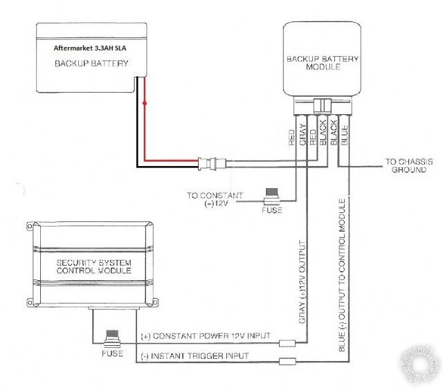
and this is how i installed my backup battery
the instant trigger is wired to 24pin aux/shut/trig harness
10 BLUE (-)TRUNK PIN/INSTANT TRIGGER INPUT (N/C OR N/O) --- Instant trigger
Posted By: smokeman1
Date Posted: November 07, 2014 at 6:41 PM
RED / Black and Red to constant 12volt
Remove green from starter wire (yellow) and connect violet
-------------
When all else fails, Read the Instructions
Support the12volt.com Make a Donation
Posted By: kreg357
Date Posted: November 07, 2014 at 6:46 PM
1 NC No Connection- - - - - -- - - - -- - Not used
2 RED / BLACK (+) FUSED 12V ACCESSORY/STARTER INPUT +12V Constant
3 PINK/BLACK (+) FLEX RELAY INPUT 87A FLEX RELAY- - - - Not used
4 PINK/WHITE (+) IGNITION 2 / FLEX RELAY OUTPUT- - - - - Not used
5 RED (+) FUSED 12V IGNITION 1 INPUT - - - - - - - - - - - - +12V Constant
6 GREEN (+) STARTER INPUT (KEY SIDE ) - - - - YELLOW @ IGNITION SWITCH ( cut wire )
7 VIOLET (+) STARTER OUTPUT (CAR SIDE ) - - - - - - Yellow @ IGNITION SWITCH ( cut wire )
8 ORANGE (+) ACCESSORY OUTPUT - - - - - - - - - - - - - - Not used
9 RED / WHITE (+) FUSED 12V IGNITION 2 / FLEX RELAY INPUT Not used
10 PINK (+) IGNITION 1 INPUT/OUTPU - - - - - - - - - - - - - - PINK/WHITE IGNITION SWITCH ------------- Soldering is fun!
Posted By: oleg4
Date Posted: November 07, 2014 at 7:44 PM
thx for the reply, one more question the instant trigger from the back up battery, did i connect it correctly.
this is how i connected it
24pin aux/shut/trig harness
10 BLUE (-)TRUNK PIN/INSTANT TRIGGER INPUT (N/C OR N/O) --- Instant trigger Back Up Battery
|