acc + ign.sw viper-omegalink
Printed From: the12volt.com
Forum Name: Car Security and Convenience
Forum Discription: Car Alarms, Keyless Entries, Remote Starters, Immobilizer Bypasses, Sensors, Door Locks, Window Modules, Heated Mirrors, Heated Seats, etc.
URL: https://www.the12volt.com/installbay/forum_posts.asp?tid=137719
Printed Date: April 27, 2026 at 5:11 AM
Topic: acc + ign.sw viper-omegalink
Posted By: mediaman
Subject: acc + ign.sw viper-omegalink
Date Posted: November 17, 2014 at 12:37 PM
I NEED TO KNOW IF ACC+ SIGNAL FROM IGNITION SWITCH NEEDS TO CONNECT TO VIPER 4806V, THE BYPASS MODULE OL-AL(MDB)-GM2 DOCUMENT #8871 SHOWS THAT IT DOES.BUT,THEIR DRAWING SHOWS A GENERIC REMOTE STARTER.
THANK YOU.
-------------
1616884422
Replies:
Posted By: kreg357
Date Posted: November 17, 2014 at 6:28 PM
Absolutely.
------------- Soldering is fun!
Posted By: mediaman
Date Posted: November 18, 2014 at 12:48 PM
Thank You, I believe that it would be connected to the "Remote Start,8-pin connector" but not clear of how. It appears as well, that pins 1,4 and 7 of the same connector would tie together and go to constant 12v., is that correct ? I would appreciate if you would clear all that up for me.
Thanks,again.
-------------
1616884422
Posted By: mediaman
Date Posted: November 18, 2014 at 1:40 PM
PLEASE CORRECT ME IF I'M WRONG.I BELIEVE IT'S PIN 6 ORANGE(+)ACC.OUTPUT TO FEED IGN. SW. ACC+ ,AND PIN 5 VIOLET(+) STARTER OUTPUT GOES TO IGN.SW.START WIRE. AND 1,4 AND 7 PROVIDES THE HOT FOR THE RELAYS.
-------------
1616884422
Posted By: kreg357
Date Posted: November 18, 2014 at 7:30 PM
4806V Remote Start, 8-pin connector
1 RED / BLACK (+) 12VDC INPUT for ACC & starter +12V Constant
2 PINK/BLACK (+) FLEX RELAY INPUT 87A not used
3 PINK/WHITE (+) IGNITION 2 / FLEX OUTPUT not used
4 RED (+) 12VDC INPUT for ignition 1 +12V constant
5 VIOLET (+) STARTER OUTPUT not used
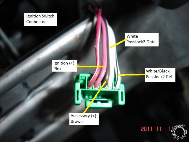
6 ORANGE (+) ACCESSORY OUTPUT to Green 6 pin plug, Pin 4 Brown (+) Ignition switch ***
7 RED / WHITE (+) 12VDC INPUT for Flex not used
8 PINK (+) IGNITION 1 INPUT/OUTPUT to Green 6 pin plug, Pin 3 Pink (or Yellow) (+) Ignition switch
*** Also goes to OL-AL(MDB)-GM2 BLACK/ White Accessory Input wire
There is no vehicle ignition "Starter wire" at the main ignition switch harness.
There is no vehicle need for the Viper Flex Relay Pink/White wire and therefore no need to connect the RED / White wire to
+12V constant ( won't hurt to connect it but...).
The vehicles White wire at Pin 5 of the ignition switch is actually a MUX wire and is controller by the bypass module.
Therefore, no direct connections from the Viper to this wire. Follow the above Remote Start, 8-pin connector wiring
listed. ------------- Soldering is fun!
Posted By: mediaman
Date Posted: November 18, 2014 at 7:56 PM
Sounds good,ignition switch pin 5 on doc.#8871, type 2 wiring from Omegalink, shows it to be Passlock and wire is cut.Then bypass module ,WTE/BLK to IGN.SW. connector and WTE/RED spliced with YEL. goes to the cut wire to the vehicle side.They also show +12v power to ignition switch pin 2.Shouldn't I take all constant +12v from BCMx3,+12V. 50AMP RED / blk WIRE ?
Thank You.
-------------
1616884422
Posted By: kreg357
Date Posted: November 18, 2014 at 8:01 PM
i need to know if acc+ signal from ignition switch needs to connect to viper 4806v, the bypass module ol-al(mdb)-gm2 document #8871 shows that it does.but,their drawing shows a generic remote starter.
thank you.
-------------
Soldering is fun!
Posted By: mediaman
Date Posted: November 18, 2014 at 8:24 PM
What do you think about the below wiring ?
Ignition switch pin 5 on doc.#8871, type 2 wiring from Omegalink, shows it to be Passlock and wire is cut.Then bypass module ,WTE/BLK to IGN.SW. connector and WTE/RED spliced with YEL. goes to the cut wire to the vehicle side.
-------------
1616884422
Posted By: mediaman
Date Posted: November 18, 2014 at 8:27 PM
I see you already mentioned that it's controlled by the Bypass module but they don't refer it by MUX
-------------
1616884422
Posted By: kreg357
Date Posted: November 18, 2014 at 8:54 PM
Yes, it is described as Passlock but it does a couple of functions. Take a look at DEI TechTip 1605 to see what the bypass modules is really doing to that White wire. Here is a link to a ZIP file that includes Tech Tip 1605 : https://www.the12volt.com/installbay/file.asp?ID=1080 ------------- Soldering is fun!
Posted By: mediaman
Date Posted: November 18, 2014 at 9:14 PM
I have worked in Electronics for a lot of yrs.and I really get into technical stuff.
Thanks for the notes.
-------------
1616884422
Posted By: mediaman
Date Posted: November 19, 2014 at 5:27 PM
Kreg357 , PM me about diagram.
Thanks
-------------
1616884422
Posted By: mediaman
Date Posted: November 26, 2014 at 12:32 AM
I completed the installation , Thank You to all that helped.
-------------
1616884422
|