viper 211 hv, mini peterbilt
Printed From: the12volt.com
Forum Name: Car Security and Convenience
Forum Discription: Car Alarms, Keyless Entries, Remote Starters, Immobilizer Bypasses, Sensors, Door Locks, Window Modules, Heated Mirrors, Heated Seats, etc.
URL: https://www.the12volt.com/installbay/forum_posts.asp?tid=138288
Printed Date: May 14, 2026 at 6:21 AM
Topic: viper 211 hv, mini peterbilt
Posted By: wanes world
Subject: viper 211 hv, mini peterbilt
Date Posted: January 17, 2015 at 10:00 PM
I'm having issues connecting the Viper 211 HV to my project build. The wiring diagram is confusing. Can someone point me in the right direction?
-------------
WAYNES WORLD
Replies:
Posted By: tedmond
Date Posted: January 18, 2015 at 8:21 AM
vehicle?
-------------
Ted
2nd Year Tier 1 Medical School
Still installing as a hobby...pays for groceries
Compustar Expert
Posted By: davep.
Date Posted: January 18, 2015 at 12:00 PM
The 211 has on-board door lock relays, and 6 wires are associated with the locks. The 211 is about as basic as installs come. Most of the wire functions should be self-explanatory. Get those connected up and the alarm system functioning. Then deal with the locks.
From observation here, some DIY's and novices have difficulty understanding lock system wiring and interfaces. Knowing the vehicle, or what the lock system is if a custom-build, peeps here can tell you the wiring connections for the 6 211's lock wires.
Posted By: howie ll
Date Posted: January 18, 2015 at 1:23 PM
Dave, without further info from the OP there's no point in proceeding although we could make an assumption ref Spal/Mes.
-------------
Amateurs assume, don't test and have problems; pros test first. I am not a free install service.
Read the installation manual, do a search here or online for your vehicle wiring before posting.
Posted By: wanes world
Date Posted: January 18, 2015 at 5:43 PM
Guys,
The truck is a conversion to a mini Peterbilt in my garage .
I followed the "directions". The red, yellow & orange are hots. The black is ground. The grn/blk , & the blue/ blk are the wires to the actuators. Violet & violet/blk are hots to the circuits. This is where I can't get the fobs to open or close the locks. I used myPower Probe to check all four actuators & they function well. This is where I'm at now.
The conversion in based on my 96 Dodge 2500 dieiselrace truck.
Is there any ideas?
WAYNES WORLD
-------------
WAYNES WORLD
Posted By: wanes world
Date Posted: January 18, 2015 at 5:49 PM
davep. wrote:
The 211 has on-board door lock relays, and 6 wires are associated with the locks. The 211 is about as basic as installs come. Most of the wire functions should be self-explanatory. Get those connected up and the alarm system functioning. Then deal with the locks.
From observation here, some DIY's and novices have difficulty understanding lock system wiring and interfaces. Knowing the vehicle, or what the lock system is if a custom-build, peeps here can tell you the wiring connections for the 6 211's lock wires.
davep,
the unit has 18 wires on the box. I just posted the ones I used but it still doesn't work.
That's why I'm puzzled as to the cause of my issues..
WAYNES WORLD ------------- WAYNES WORLD
Posted By: davep.
Date Posted: January 18, 2015 at 6:31 PM
wanes world wrote:
Is there any ideas?
WAYNES WORLD
My responses begin with --
Guys,The truck is a conversion to a mini Peterbilt in my garage .
--Sounds like a cool Project.
I followed the "directions". The red, yellow & orange are hots.
-- red H1/1 = hot at all times
-- Yellow H1/15 = Hot with IGN ON only.
-- Orange H1/16 = ground when armed. You shouldn't need this. Disconnect it.
The black is ground.
-- Black H1/11, correct, is ground.
The grn/blk , & the blue/ blk are the wires to the actuators.
--Correct. Lock and unlock sides of the actuators.
Violet & violet/blk are hots to the circuits.
--These two should be Hot at all times. Fuse them, too.
-- ^^ These 4 connections should now be correct depending on how the manual switches (if any) are wired.
-- If you do NOT have manual switches for the actuators, (this is a stand-alone RKE-only system) then you need to connect:
Brn/blk and the wht/blk wires to Ground.
-- IF you DO have interior manual switches, report back how these are wired to the actuators. You can try it first, but if it blows fuses, we'll have to figure out how the switches are wired. Are they the stock Dodge wiring and switches?
This is where I can't get the fobs to open or close the locks.
-- Connect the brn/blk and wht/blk wires to ground.
-- Some DEI's won't actuate the locks if the IGN is on (the yellow wire) so connect that to an IGN-only source, and try the locks again.
There's some ideas.
I KNEW this was "something special" Howie. That's why I replied the way I did in the first post. Cheers. DP.
Posted By: davep.
Date Posted: January 18, 2015 at 6:59 PM
davep. wrote:
The 211 has on-board door lock relays, and 6 wires are associated with the locks. The 211 is about as basic as installs come. Get ...the alarm system functioning. Then deal with the locks.
I'm so sorry. This is a Remote Keylees Entry ONLY. No alarm. I installed an Avital 2101 two weeks ago. No wonder the wiring looked familiar. Same thing as your 211. This post should get you straightened out.
````````````````````````````
OK. If you still have the stock 1996 Dodge lock wiring and switches, use this diagram as a guide. Here's the way I would do it.
At the passenger switch, Cut the pnk/blk and orn/blk wires in two.
Connect switch-side pnk/blk to 211 brn/blk.
Connect switch-side orn/blk to 211 wht/blk.
Connect motor-side pnk/blk to 211 blu/blk.
Connect motor-side orn/blk to 211 grn/blk.
Connect 211 violet and violet/blk to FUSED Hot at all times. (Tap the red wire at door switch would be acceptable as well).
I triple-checked the above. It will work, if the Dodge wiring is still in the below configuration.
EDIT: Is this your truck? The red one? 12.94? That's a lot of iron to move that quickly. I'm a Syclone Owner, and don't worry too much about being beat on the street, but I'd loose to you if you had time to spool-up. Pretty cool stuff.
  [/IMG]
Posted By: wanes world
Date Posted: January 18, 2015 at 7:43 PM
Guys,
I'm looking into these responses. I appreciate the info.
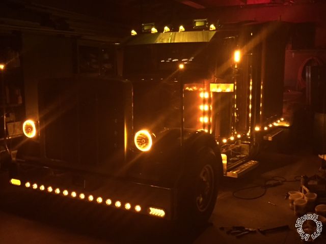
This is my truck--------
I'll get back with the results -- I hope soon.
Thank You,
WAYNES WORLD ------------- WAYNES WORLD
Posted By: wanes world
Date Posted: January 18, 2015 at 8:08 PM
davep. wrote:
wanes world wrote:
Is there any ideas?
WAYNES WORLD
My responses begin with --
Guys,The truck is a conversion to a mini Peterbilt in my garage .
--Sounds like a cool Project.
I followed the "directions". The red, yellow & orange are hots.
-- red H1/1 = hot at all times
-- Yellow H1/15 = Hot with IGN ON only.
-- Orange H1/16 = ground when armed. You shouldn't need this. Disconnect it.
This is my first order of business--------
The black is ground.
-- Black H1/11, correct, is ground.
This is correct-----
The grn/blk , & the blue/ blk are the wires to the actuators.
--Correct. Lock and unlock sides of the actuators.
This is correct-----
Violet & violet/blk are hots to the circuits.
--These two should be Hot at all times. Fuse them, too.
This is a single wire that is done--------
-- ^^ These 4 connections should now be correct depending on how the manual switches (if any) are wired.
I hope the grn/blk & blu/blk are the wires you speak of-----
-- If you do NOT have manual switches for the actuators, (this is a stand-alone RKE-only system) then you need to connect:
I do have a master switch on the drivers door-----
Brn/blk and the wht/blk wires to Ground.
This appears to be my error------:-(
-- IF you DO have interior manual switches, report back how these are wired to the I do not have any separate switches for the door locks except the master in the drivers door. It is actuators. You can try it first, but if it blows fuses, we'll have to figure out how the switches are wired. Are they the stock Dodge wiring and switches?
This is where I can't get the fobs to open or close the locks.
-- Connect the brn/blk and wht/blk wires to ground.
-- Some DEI's won't actuate the locks if the IGN is on (the yellow wire) so connect that to an IGN-only source, and try the locks again.
I'll move that yellow -----
There's some ideas.
I KNEW this was "something special" Howie. That's why I replied the way I did in the first post. Cheers. DP.
Guys---- check out that lights only photo. This is the project thus far. Stay tuned -----
Thank You,
WAYNES WORLD ------------- WAYNES WORLD
Posted By: wanes world
Date Posted: January 18, 2015 at 8:18 PM
Davep,
YES that's my truck ! It has posted some 11's before I started this conversion 3 years ago. I didn't realize I had a video that old on Youtube. Thank You ! :-)
Now that the Lil Pete has dieted , it should be faster----I hope !
My truck doesn't have any stock wiring except for the engine & chassis.
Thanks for the great info.
WAYNES WORLD
-------------
WAYNES WORLD
Posted By: wanes world
Date Posted: January 24, 2015 at 3:45 PM
Guys,
Tried to adjust the wires -----no luck except for locking when held for 4-5 seconds.
I tried each door actuator by itself & they all work at each door.
The box makes noise with each lock or unlock button.
One last thing is the blue light doesn't work.
I have the manual door button wired with WHITE/ BROWN / black wires to make it work.
This is puzzling-----
WAYNES WORLD
-------------
WAYNES WORLD
Posted By: wanes world
Date Posted: January 24, 2015 at 4:25 PM
Davep,
New wrinkle,
I disconnected the yellow ---- the doors lock & the blue light flashes like it should !
But the fob won't unlock the doors?
I'm getting closer-------
WAYNES WORLD
-------------
WAYNES WORLD
Posted By: wanes world
Date Posted: January 24, 2015 at 4:54 PM
Davep,
The remaining wires----
2--blue nothing
3--brn horn nothing
4--blk/wht light nothing
13--grn/blk light nothing
14----wht/blue nothing
18--RED / wht nothing
10-- parking works
16-- org grd works
This latest wrinkle makes the doors unlock Plus the blue light works perfectly.
I'm getting much closer.
Any thoughts?
WAYNES WORLD
-------------
WAYNES WORLD
Posted By: davep.
Date Posted: January 24, 2015 at 8:58 PM
I'm completely lost. I have not a clue how you have things wired. I don't know what door switches you're using. Wire colors mean nothing to me, unless you tell me what they go to or from.
Print the following diagram out. Study it until you understand how the STOCK lock system works. Then pencil the following 211 hook-ups into the diagram:
At the passenger switch, Cut the pnk/blk and orn/blk wires in two.
Connect switch-side pnk/blk to 211 brn/blk. (87a unlock)
Connect switch-side orn/blk to 211 wht/blk. (87a lock)
Connect motor-side pnk/blk to 211 blu/blk. (30 unlock)
Connect motor-side orn/blk to 211 grn/blk. (30 lock)
Connect 211 violet (87 unlock) and violet/blk (87 lock) to FUSED Hot at all times. (Tap the red wire at door switch would be acceptable as well).
IF you can explain how the current door switches are wired, I MAY be able to tell you how to interface the 211 to your existing configuration.
Please start reading my posts carefully. If I ask a specific question, answer it. Or make a specific location to connect a particular wire to, do it. Answers to the questions provide clues as to what to ask next, or tell you to try next. But random "I disconnected this, now I'm closer" isn't very helpful. Other than I think you have the yellow wire connected to a 12V at all times source. Which you said you had connected to "hot" in your opening post. In my first response I told you how to connect those wires, and now you're getting around to following my suggestion?
Please study this stuff until you figure out how a stock lock system works. And then I think you'll understand how to wire your locks to the 211.
#16 orange shouldn't be connected to anything.
Here is one more study aid. If you were to substitute the 211 for either door switch in the below diagram, here's how you would hook it up. The "pin" corresponds to the door switch terminal in the diagram. The number in parentheses indicates the terminal if it were a relay. There are several sections on this forum to help you understand relays. If you know relay terminal functions, then this should help you understand what's going on inside the 211.
pin1 = grn/blk Lock Common (30)
pin2 = brn/blk Unlock N/C (87a)
pin3 = violet Unlock N/O B+ Power (87)
pin3 = vio/blk Lock N/O B+ Power (87)
pin4 = wht/blk Lock N/C (87a)
pin5 = blu/blk Unlock Common (30)
 [/IMG]
Posted By: wanes world
Date Posted: January 24, 2015 at 10:10 PM
Davep,
I'm sorry this is so frustrating !
This project is a kit. There is no stock wiring at all. The doors were wired with a BF-05 Bai Feng Chinese 4 door lock system. The switches are in photo. the Chinese wiring system in photo. 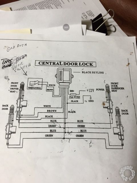 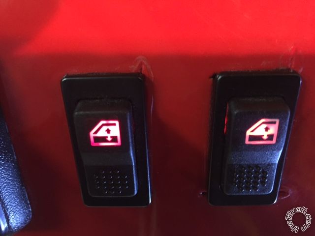
I hope this helps. This is how confusing it gets for me as well.
The yellow isn't connected to anything. Its setting on the steering wheel with the other 7 wires that are not going to be hooked up. The white h1/10 does work. the 2 3 4 13 14 18 don't do anything when the key fob is pushed.
Does this help?
Thank You,
WAYNES WORLD ------------- WAYNES WORLD
Posted By: davep.
Date Posted: January 25, 2015 at 12:04 AM
Now we're getting somewhere.
violet and violet/ black to ground.
grn/blk to white at door switch
blu/blk to brown at door switch.
If lock and unlock are "backwards", reverse the second two connections.
Posted By: wanes world
Date Posted: January 25, 2015 at 12:18 AM
Davep,
I'll give that a try tomorrow.
Which wire goes to the other actuators?
Thank You very Much,
-------------
WAYNES WORLD
Posted By: davep.
Date Posted: January 25, 2015 at 12:26 AM
Does the door switch lock and unlock both doors?
If so, those connections will work. They will have the 211 doing the same thing electrically that the door switch does. No 211 wiring goes to the actuators.
Wire the actuators and module as shown in the "Central Locking System" diagram.
Posted By: wanes world
Date Posted: January 25, 2015 at 12:30 AM
Davep,
I really appreciate your patience in helping me with this issue.
Thank You,
WAYNES WORLD
-------------
WAYNES WORLD
Posted By: wanes world
Date Posted: January 25, 2015 at 2:34 PM
davep. wrote:
Now we're getting somewhere.
violet and violet/ black to ground.
grn/blk to white at door switch
blu/blk to brown at door switch.
If lock and unlock are "backwards", reverse the second two connections.
Davep,
violet & violet/blk has a fuse inline ----- why should it go to grd?
The door switch does unlock all the doors.
I followed the above suggestions but now it doesn't lock or unlock.
It blew the fuse in violet & violet/blk
Here's the wiring set up----
1--red hot
2--blue not hooked up
3/4--blk/wht dome light doesn't work
5--grn/blk lock doors
6--wht/blk not hooked up
7/9--violet &violet/lk hots
8--blue/blk unlock works when fob is hit but doesn't unlock
10--white parking lights works with fob the only one that does
11--blk-- grd
12--brn horn but no output with fob
13--lt grn/blk factory alarm no output with fob
14--wht/blu no output with fob
15--yellow switched hot not hooked up
16--orange not hooked up
17--brn/blk i have it grounded
18--RED / wht nothing from fob
This is the 211 wires ----am I doing this right?
What would be best?
Thank You,
WAYNES WORLD ------------- WAYNES WORLD
Posted By: wanes world
Date Posted: January 25, 2015 at 2:39 PM
Davep,
One more point to consider ---
When I put power to the lock or unlock they work all 4 doors.
I tested the output from the 211 with the testlight, it puts out power as signaled but doesn't lock the doors. Where as it does unlock the doors after a few seconds.
Does this make sense to you?
WAYNES WORLD
-------------
WAYNES WORLD
Posted By: davep.
Date Posted: January 25, 2015 at 8:37 PM
Yes or no to the following questions, please:
Disconnect all connections from the lock circuits to the 211.
Cycle the locks with the door switch. Do the locks work normally from the door switch?
If = yes, continue.
Look at the door switch is there a white and a brown wire?
If = yes, continue.
Probe the white wire with a test lead connected to ground.
Do the locks lock or unlock?
If = yes, is it lock or unlock? Make a note of which it is.
Now probe the brown wire with a test lead connected to ground.
Do the locks lock or unlock?
If = yes, is it lock or unlock? Make a note of which it is.
If there are any "no" answers to the above, post the results.
If you answer "yes" to all the above questions, you should now know that grounding the brown and white wire at the door switch operates the locks. I will tell you how to connect the 211. continue reading..
```````````````````````````
Here's a cut and paste of your connections above.Corrections are in bold. Comments are in parentheses. Connect your 211 EXACTLY the way the table below says to. If grounding the white and brown wires at the switch lock and unlock the doors, It will work. EXACTLY! Print this post out, and take it to the shop. EXACTLY.
It's only 7 wires, including the park lights. When you get done, only 7 wires should be connected:
3 to Ground,
1 red to 12V,
2 to door switch,
1 to park lights.
1--red hot (12 V at all times)
2--blue N/C
3/4--blk/wht N/C and N/C
5--grn/blk LOCK = White wire at door switch, if white locks. Brown, if brown locks.
6--wht/blk N/C
7/9--violet &violet/blk Connect to GROUND
8--blue/blk UNLOCK = White wire at door switch, if white unlocks. Brown, if brown unlocks.
10--white parking lights
11--blk-- grd
12--N/C
13--N/C
14--N/C
15--N/C IGN input. (Don't need it for now. Leave N/C).
17--N/C (brn/blk I have it grounded. Disconnect it. This is why you blew the fuse).
18--N/C
This is a simple as I can make it for you. If you can't make it work from this post (its only 7 wires) I admit I fail as an instructor. I have many HOURS in these posts now. If it still doesn't work, I don't know what to try with you next, but I have to throw in the towel. Hope you get it this time.
Take Care.
Dave P
Posted By: wanes world
Date Posted: January 25, 2015 at 9:15 PM
Davep,
I see your ideas but it may take a while to get back to the garage due to work schedule. Truck drivers get no free time usually during the week. I will get back for sure on sat.
Thank You,
WAYNES WORLD
-------------
WAYNES WORLD
Posted By: wanes world
Date Posted: January 31, 2015 at 4:15 PM
davep. wrote:
Yes or no to the following questions, please:
Disconnect all connections from the lock circuits to the 211.
Cycle the locks with the door switch. Do the locks work normally from the door switch?
If = yes, continue.
Nothing works-------
Look at the door switch is there a white and a brown wire?
If = yes, continue.
Yes----- they go inside the dash------
Probe the white wire with a test lead connected to ground.
Do the locks lock or unlock?
If = yes, is it lock or unlock? Make a note of which it is.
They connect to nothing--------
Now probe the brown wire with a test lead connected to ground.
Do the locks lock or unlock?
If = yes, is it lock or unlock? Make a note of which it is.
SAME --not connected
If there are any "no" answers to the above, post the results.
If you answer "yes" to all the above questions, you should now know that grounding the brown and white wire at the door switch operates the locks. I will tell you how to connect the 211. continue reading..
```````````````````````````
Here's a cut and paste of your connections above.Corrections are in bold. Comments are in parentheses. Connect your 211 EXACTLY the way the table below says to. If grounding the white and brown wires at the switch lock and unlock the doors, It will work. EXACTLY! Print this post out, and take it to the shop. EXACTLY.
It's only 7 wires, including the park lights. When you get done, only 7 wires should be connected:
3 to Ground,
1 red to 12V,
2 to door switch,
1 to park lights.
1--red hot (12 V at all times)
2--blue N/C
3/4--blk/wht N/C and N/C
5--grn/blk LOCK = White wire at door switch, if white locks. Brown, if brown locks.
6--wht/blk N/C
7/9--violet &violet/blk Connect to GROUND
These must be to hot to wrk the lock-----they have a fuse just like the red hot wire----
8--blue/blk UNLOCK = White wire at door switch, if white unlocks. Brown, if brown unlocks.
When I do this absolutely nothing happens
10--white parking lights
11--blk-- grd
12--N/C
13--N/C
14--N/C
15--N/C IGN input. (Don't need it for now. Leave N/C).
17--N/C (brn/blk I have it grounded. Disconnect it. This is why you blew the fuse).
18--N/C
This is a simple as I can make it for you. If you can't make it work from this post (its only 7 wires) I admit I fail as an instructor. I have many HOURS in these posts now. If it still doesn't work, I don't know what to try with you next, but I have to throw in the towel. Hope you get it this time.
Take Care.
Dave P
Think how I feel ! Please note the 7/9 has a fuse ----- my thought it must be hot! Plus it's the only way the lock FOB button makes it work !
When I connect the blu/blk or grin/blk ------ they light the test light but the locks don't work. I ground the one wire of the actuator while I apply hot to the other ---the locks work.
Any thoughts?
WAYNES WORLD
------------- WAYNES WORLD
Posted By: wanes world
Date Posted: January 31, 2015 at 4:53 PM
Davep,
I found the lone MISSING wire---------
#6---The WHITE/ black is the key to unlocking the doors.
It all works now! UNREAL !
The three wires all needed for each closed & or open circuit MUST be connected.
This is one for the books--------
It seems not all blanket solutions are right for everybody . Should I try to hook up the horn or parking lights??????
Thank You,
Wayne
-------------
WAYNES WORLD
Posted By: davep.
Date Posted: January 31, 2015 at 11:24 PM
I'm glad you have it working. I have an observation and comment.
You obviously haven't hooked it up the way I suggested, because I left 5-blk/wht Not Connected.
I don't think you even read, much less understood, anything I've written in this thread over the past two weeks. You kept fumbling around on your own until you stumbled onto getting it to work.
As far as "It seems not all blanket solutions are right for everybody" .. That's kind of an insult. You insinuate that I was guessing, or suggesting configurations without considering YOUR particular installation. Nothing could be further from the truth. I asked about your truck, its switches, etc. You FINALLY put up a diagram of the lock system. The wiring I suggested was the SIMPLEST I could come up with. 7 wires total. I (or pretty much anyone else on The 12Volt) could have suggested perhaps 5 or more OTHER ways to incorporate a 211 into that lock system. There's more than one right way to do things. I picked the SIMPLEST. You picked a more complicated solution if you're using all 6 of the 211's lock wires.
Again I'm glad you got it working. A thank-you for my patience would have been appreciated. Instead of insinuating that my suggestions were a waste of time because that's not the configuration you used to get it to work. They would have worked just fine. You chose to ignore them.
Posted By: wanes world
Date Posted: January 31, 2015 at 11:37 PM
davep. wrote:
I'm glad you have it working. I have an observation and comment.
You obviously haven't hooked it up the way I suggested, because I left 5-blk/wht Not Connected.
ECUSE ME ---- Dave but just 2 post up you have it NC
I don't think you even read, much less understood, anything I've written in this thread over the past two weeks. You kept fumbling around on your own until you stumbled onto getting it to work.
It seems to reflect the above again.
As far as "It seems not all blanket solutions are right for everybody" .. That's kind of an insult. You insinuate that I was guessing, or suggesting configurations without considering YOUR particular installation. Nothing could be further from the truth. I asked about your truck, its switches, etc. You FINALLY put up a diagram of the lock system. The wiring I suggested was the SIMPLEST I could come up with. 7 wires total. I (or pretty much anyone else on The 12Volt) could have suggested perhaps 5 or more OTHER ways to incorporate a 211 into that lock system. There's more than one right way to do things. I picked the SIMPLEST. You picked a more complicated solution if you're using all 6 of the 211's lock wires.
I NEVER MEANT TO INSUST YOU IN ANY WAY ! IN FACT YOU HAVE GONE OUT OF YOUR WAY TO BELITTLE ME--------
Again I'm glad you got it working. A thank-you for my patience would have been appreciated.
Thank You-----
Instead of insinuating that my suggestions were a waste of time because that's not the configuration you used to get it to work. They would have worked just fine. You chose to ignore them.
I don't like to repeat myself but I have said thank you every single time I replied HAVE YOU EVER THOUGHT OF RETURNING A COMPLIMENT ------To ANYBODY ??
Have a nice day-------- Wayne ------------- WAYNES WORLD
Posted By: oldspark
Date Posted: February 01, 2015 at 2:06 AM
Yeah Dave! Look how often I thank people for getting me to assist them with their headaches - especially when my repeatedly sought advice is repeatedly ignored.
You should also be thankful for your tax savings - by solving issues here you avoid the tax burden resulting from professional visit or consultation charges etc.
Of course I might have missed something... I have only looked at the last reply or two and the opening postings.
Posted By: howie ll
Date Posted: February 01, 2015 at 2:51 AM
I hope our friend doesn't have to ever control 1 wire multiplex locks.
-------------
Amateurs assume, don't test and have problems; pros test first. I am not a free install service.
Read the installation manual, do a search here or online for your vehicle wiring before posting.
|