2009 Corolla Japanese Made.
Printed From: the12volt.com
Forum Name: Car Security and Convenience
Forum Discription: Car Alarms, Keyless Entries, Remote Starters, Immobilizer Bypasses, Sensors, Door Locks, Window Modules, Heated Mirrors, Heated Seats, etc.
URL: https://www.the12volt.com/installbay/forum_posts.asp?tid=138637
Printed Date: March 24, 2026 at 7:19 AM
Topic: 2009 Corolla Japanese Made.
Posted By: cherxiong
Subject: 2009 Corolla Japanese Made.
Date Posted: March 10, 2015 at 1:26 PM
Please help me identify the ignition switch wire.
I have 8 pin plug.
Pin 1 has a white wire,
Pin 2 has two black wires,
Pin 3 has a yellow wire,
Pin 4 is emptied,
Pin 5 has 2 white wires.
Pin 6 has a white wire,
pin 7 has a Gray wire,
Pin 8 is emptied.
Thanks in advance.
Replies:
Posted By: howie ll
Date Posted: March 10, 2015 at 1:39 PM
TEST
With first ACC, then IGN, then crank.
-------------
Amateurs assume, don't test and have problems; pros test first. I am not a free install service.
Read the installation manual, do a search here or online for your vehicle wiring before posting.
Posted By: howie ll
Date Posted: March 10, 2015 at 1:44 PM
You've got 2 X IGN., 2 X start, ACC and at least 1 12V+ constant input.
-------------
Amateurs assume, don't test and have problems; pros test first. I am not a free install service.
Read the installation manual, do a search here or online for your vehicle wiring before posting.
Posted By: cherxiong
Date Posted: March 10, 2015 at 3:18 PM
Thank you so much Howie II
Posted By: cherxiong
Date Posted: March 10, 2015 at 5:59 PM
Howeii. Is it possible to have two 12DCV constant. Two pin always stay at 12DCV when I tested.
Posted By: howie ll
Date Posted: March 10, 2015 at 6:40 PM
Yes, nearly always on Toyotas. Sorry, I should have mentioned that above.
-------------
Amateurs assume, don't test and have problems; pros test first. I am not a free install service.
Read the installation manual, do a search here or online for your vehicle wiring before posting.
Posted By: cherxiong
Date Posted: March 11, 2015 at 9:07 AM
Thanks again for confirming, your time, and your help. I have more confidence now.
:))))
Posted By: cherxiong
Date Posted: March 12, 2015 at 11:14 AM
Howeii, sorry to bother you again. I am trying to hook up my remote car starter. My question is why do I have two start wires in one pin (Pin 5)? How do I know which wire to connect my starter wire out put from the remote starter. Also the Accessory also has two wires. Howeii , please advise.
My remote starter:
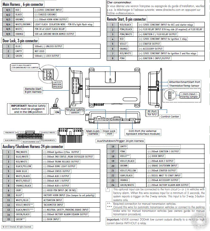
Remote Start, 8-pin connector
1. RED / BLACK (+) 12VDC CONSTANT INPUT for ACC and starter relays
2. PINK/BLACK (+) FLEX RELAY INPUT 87A key side (if required) of FLEX RELAY
3. PINK/WHITE (+) IGNITION 2 / FLEX RELAY OUTPUT
4. RED (+) 12VDC CONSTANT INPUT for ignition 1 relay
5. VIOLET (+) STARTER OUTPUT
6. ORANGE (+) ACCESSORY OUTPUT
7. RED / WHITE (+) 12VDC CONSTANT INPUT for ignition 2 and flex relays
8. PINK (+) IGNITION 1 INPUT/OUTPUT
Posted By: howie ll
Date Posted: March 12, 2015 at 11:21 AM
Hook the violet to either if they share a pin.
You should have 2 IGN. wires pink to one, pink/white to the other.
Orange to one ACC then H2 orange (thin wire) to relay 85
Relay 86 and 87 to 20 amp fused constant.
30 to second ACC. Diode 1N4004 across 85 and 86, band to 86.
Pink/black not used.
-------------
Amateurs assume, don't test and have problems; pros test first. I am not a free install service.
Read the installation manual, do a search here or online for your vehicle wiring before posting.
Posted By: cherxiong
Date Posted: March 12, 2015 at 11:43 AM
Thanks.
How about these two wires below here. Should I hook them to the constant wires of the key switch? or "Do Not Use" like the Pink/Black you've mentioned
1. RED / BLACK (+) 12VDC CONSTANT INPUT for ACC and starter relays
7. RED / WHITE (+) 12VDC CONSTANT INPUT for ignition 2 and flex relays
Posted By: howie ll
Date Posted: March 12, 2015 at 11:45 AM
Yes.
You might also have to get an immobiliser by-pass as well.
-------------
Amateurs assume, don't test and have problems; pros test first. I am not a free install service.
Read the installation manual, do a search here or online for your vehicle wiring before posting.
Posted By: cherxiong
Date Posted: March 12, 2015 at 12:05 PM
Thanks again for all the valuable information. I bought the by-pass module already. I will hook them up and let you know : )
Posted By: tedmond
Date Posted: March 12, 2015 at 1:22 PM
the idatalink ads-alca works great on this car.
i use the 12v at the fuse box. It's a fairly large gauge, white or black single wire
-------------
Ted
2nd Year Tier 1 Medical School
Still installing as a hobby...pays for groceries
Compustar Expert
Posted By: cherxiong
Date Posted: March 12, 2015 at 1:33 PM
Thanks Ted. I know. I did research and saw on youtube seem to be large wire, but when I look at all the wires at the key switch harness and see that they are all so small. I need to be triple quadruple more careful about them.
Thanks for pointing out.
Posted By: howie ll
Date Posted: March 12, 2015 at 2:03 PM
You can use the ignition wires but the white fusebox battery input is a better source.
-------------
Amateurs assume, don't test and have problems; pros test first. I am not a free install service.
Read the installation manual, do a search here or online for your vehicle wiring before posting.
Posted By: tedmond
Date Posted: March 12, 2015 at 3:07 PM
for all your outputs, its best to solder on a smaller gauge wire to the large gauge, then wire it at the ignition. I have seen cases where the added weight causes the factory wire to break.
-------------
Ted
2nd Year Tier 1 Medical School
Still installing as a hobby...pays for groceries
Compustar Expert
Posted By: cherxiong
Date Posted: March 12, 2015 at 4:19 PM
Very good advice. Haven't think of that. Thanks
Posted By: howie ll
Date Posted: March 13, 2015 at 3:18 AM
I de-pin the heavy gauge plug, have the right connectors and insert smaller gauge wires then use a single 15 amp fuse, all you need.
In your case do as Ted suggested.
-------------
Amateurs assume, don't test and have problems; pros test first. I am not a free install service.
Read the installation manual, do a search here or online for your vehicle wiring before posting.
Posted By: cherxiong
Date Posted: March 13, 2015 at 5:40 AM
Thanks to both of you. It's my first time. Very exciting to learn new experience.
Posted By: howie ll
Date Posted: March 13, 2015 at 6:22 AM
If you have any problems, post your wiring and what wires they are connected to.
You haven't mentioned what you're installing, I assume a DEI product.
-------------
Amateurs assume, don't test and have problems; pros test first. I am not a free install service.
Read the installation manual, do a search here or online for your vehicle wiring before posting.
Posted By: cherxiong
Date Posted: March 13, 2015 at 6:36 AM
Thank you. I just don't want to be too much burden. I am trying to install Viper 4706V. DBALL2 by-pass flashing with XKLOADER2
Posted By: cherxiong
Date Posted: March 13, 2015 at 7:02 AM
Howeii and Ted
Do I need the Biwriter to program the Viper or the DBALL2? or any thing else?
Posted By: howie ll
Date Posted: March 13, 2015 at 7:14 AM
You need to program the DB-ALL2 via the XK loader having downloaded the program from the Xpresskit site.
Depending on whether a plug at the BCM or a driver kick panel plug controls the windows raising if so you only need the bitwriter to program aux for that function.
Frankly I'd only spend the money if you were doing lots of installs.
-------------
Amateurs assume, don't test and have problems; pros test first. I am not a free install service.
Read the installation manual, do a search here or online for your vehicle wiring before posting.
Posted By: cherxiong
Date Posted: March 13, 2015 at 7:51 AM
Howeii, I might assuming like your profile signature said. I tested the ignition switch and came out as follow. Please help me double check to confirm that I am right.
Ignition Switch 8 pin Connector
Pin 1 : White (Ignition 1) Pin 2: A pair of Black (Accessory) Pin 3: Yellow (12 V DC) Pin 4: Emptied
Pin 5: A pair of White (Starter) Pin 6: White ( 12 V DC) Pin 7: Gray (Ignition 2) Pin 8: Emptied
Tested result with Multimer Tester
Pin 1. ACC = 0 On = 12 Crank = drop to 10V DC Pin 2. ACC = 12 On = 12 Crank = drop to 10V DC Pin 3. ACC = 12 On = 12 Crank = drop to 10V DC Pin 4. No test (Emptied)
Pin 5. ACC = 0 On = 12 Crank = drop to 10V DC Pin 6. ACC = 12 On = 12 Crank = drop to 10V DC Pin 7. ACC = 12 On = 12 Crank = drop to 10V DC Pin 8. No test (Emptied)
Posted By: cherxiong
Date Posted: March 13, 2015 at 7:54 AM
Correction
Pin 7. ACC = 0 On = 12 Crank = drop to 10V DC
Posted By: howie ll
Date Posted: March 13, 2015 at 7:55 AM
Use a test light, Snap-On, Mac NOT a DMM much quicker and more reliable.
-------------
Amateurs assume, don't test and have problems; pros test first. I am not a free install service.
Read the installation manual, do a search here or online for your vehicle wiring before posting.
Posted By: howie ll
Date Posted: March 13, 2015 at 7:56 AM
I was a going to pick you up on pin 7. 
When you have pairs going to a single terminal (pin) you can connect (ONLY via solder and Scotch 33 please) to either. ------------- Amateurs assume, don't test and have problems; pros test first. I am not a free install service.
Read the installation manual, do a search here or online for your vehicle wiring before posting.
Posted By: tedmond
Date Posted: March 13, 2015 at 8:45 AM
Meter or DMM are both reliable test tools, I agree that a test light is quicker to use. Personally, my fluke dmm is used more often than the power probe.
On that note, as Howie mentioned, a bitwriter is not necessary. Even pros rarely touch the bit-writer, unless it's a "custom" setting. The programming menu is fairly sufficient for the avid DIYer. If your DBALL2 is not flashed, pick up a XK-loader if you plan to do other cars in the future. If not, it would more cost effective to have a shop flash it for 10-15 dollars.
-------------
Ted
2nd Year Tier 1 Medical School
Still installing as a hobby...pays for groceries
Compustar Expert
Posted By: howie ll
Date Posted: March 13, 2015 at 9:05 AM
X 2 with Ted. We seen all of this before where an avid amateur has all the finest (most expensive) tools. Frankly the only top of the range tools are my Snap-On spanners and sockets, Milwaukee compact combi drill and Milwaukee compact screwdriver plus Weller soldering equipment.
The only wires you mustn't probe with a tester would be data, e.g. CAN or LIN networks or airbag circuits, data wires are usually in a twisted pair and measure about 2.5 V, airbag circuits generally have yellow looms.
TBH the last late Yaris I did, I used a spare key and a 556U plus hardwire.
No need for a DB-ALL.
The other install caveat would be don't turn on the ignition with anything unplugged.
VAG are the worst offenders (airbag, ABS lights staying on) but Toyotas have been known to cause nightmares on occasion especially if not firmly plugged back in.
I have a pair of no-name DMMs with a 10 amp DC current rating, more than adequate for this kind of work.
-------------
Amateurs assume, don't test and have problems; pros test first. I am not a free install service.
Read the installation manual, do a search here or online for your vehicle wiring before posting.
Posted By: cherxiong
Date Posted: March 13, 2015 at 9:33 AM
Thanks both. You two are very formative (So generous to amateurs like me). I bought the XK-loader and flashed the By-Pass DBALL aready. Hope I got the right firm ware. I don't need to do anything with the remote starter right, besides connecting the wire and programming the remote control.
Posted By: cherxiong
Date Posted: March 13, 2015 at 9:33 AM
very informative
Posted By: cherxiong
Date Posted: March 13, 2015 at 9:38 AM
Posted By: howie ll
Date Posted: March 13, 2015 at 9:38 AM
What worries me is you mentioned Japanese build. Is this a right hand drive JDM car or one built for sale in the US?
If it's the second then the software you downloaded should be fine.
-------------
Amateurs assume, don't test and have problems; pros test first. I am not a free install service.
Read the installation manual, do a search here or online for your vehicle wiring before posting.
Posted By: cherxiong
Date Posted: March 13, 2015 at 9:53 AM
It's the one built for sale in the USA. : ). Left hand drive.
Posted By: howie ll
Date Posted: March 13, 2015 at 10:08 AM
OK then the software should be OK.
-------------
Amateurs assume, don't test and have problems; pros test first. I am not a free install service.
Read the installation manual, do a search here or online for your vehicle wiring before posting.
Posted By: cherxiong
Date Posted: March 13, 2015 at 11:06 AM
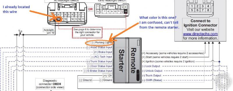
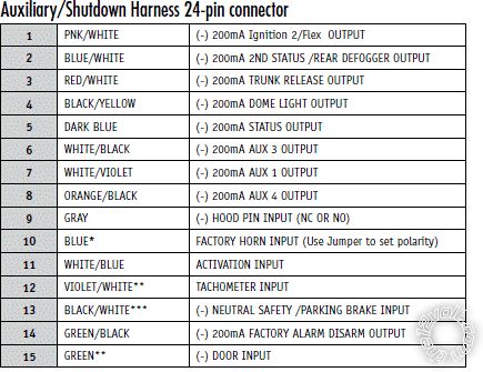
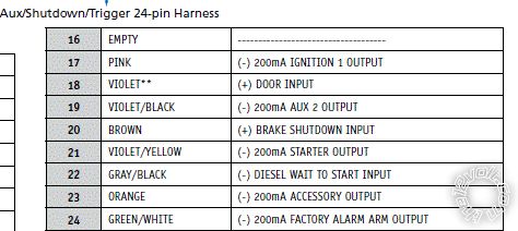
Howeii and Ted, This might be a stupid question, but which pin from the Auxilary/Shutdown Harness 24-pin connector is the parking light wire from the remote starter to connect to the Pin 18 of the 20 pin plug white connector at the headlight switch of the car.
The diagram from DBALL2 shows that I need to make this connection.
Pin 13 : BLACK/ White*** = (-) Neutral Safety/Parking Brake Input, is the closest one to the parking light mentioned in the diagram.
Posted By: howie ll
Date Posted: March 13, 2015 at 11:13 AM
Are you looking at type 1?
I can't see what you're talking about.
Pin 13 is handled by D2D on the DB-ALL, if auto just ground pin 13 BLACK/ white.
-------------
Amateurs assume, don't test and have problems; pros test first. I am not a free install service.
Read the installation manual, do a search here or online for your vehicle wiring before posting.
Posted By: howie ll
Date Posted: March 13, 2015 at 11:21 AM
You will also need to hardwire from the H2 dark blue status wire to the key sense wire,
ignition key switch or dash fuse box, white 32 pin plug (2E), pin 23.
-------------
Amateurs assume, don't test and have problems; pros test first. I am not a free install service.
Read the installation manual, do a search here or online for your vehicle wiring before posting.
Posted By: cherxiong
Date Posted: March 13, 2015 at 1:44 PM
Yes. I am talking about Type 1. I got the Hard wire for the key sense. Just not sure about the Parking Light connection on the diagram.
Posted By: howie ll
Date Posted: March 13, 2015 at 2:18 PM
Look further down, it will show you what type of connector and the colour.
-------------
Amateurs assume, don't test and have problems; pros test first. I am not a free install service.
Read the installation manual, do a search here or online for your vehicle wiring before posting.
Posted By: cherxiong
Date Posted: March 14, 2015 at 2:23 AM
I look at every page already. Still confuse. Here is a picture, not sure if it's going to come out right.
Posted By: cherxiong
Date Posted: March 14, 2015 at 2:36 AM
Which of the following is the one for (-) Parking Light
Posted By: howie ll
Date Posted: March 14, 2015 at 4:44 AM
White at H1, set the internal light flash fuse for NEG, see second diagram, there's a slider on top of the r/start unit.
That wire goes to 18 or 13 depending on which connector.
To test that it is 18 (or 13) take your test light, clip to a good ground and probe to wire, should bring on your lights.
-------------
Amateurs assume, don't test and have problems; pros test first. I am not a free install service.
Read the installation manual, do a search here or online for your vehicle wiring before posting.
Posted By: cherxiong
Date Posted: March 14, 2015 at 5:44 AM
Good morning Howeii, The H2 you mentioned above, is it the H/5? (of the Main Harness/6 pin connector). My H/2 (of the Main Harness/6 pin connector) is black and is the ground.
Posted By: cherxiong
Date Posted: March 14, 2015 at 5:49 AM
Correction : )
I meant the H1 not H2. The one that you mentioned. My H1 is the 12vdc. The white wire (of the Main Harness/6 pin connector in the second diagram)is H/5.
Posted By: cherxiong
Date Posted: March 14, 2015 at 5:51 AM
I set the internal light flash fuse for NEG already. Thanks
Posted By: howie ll
Date Posted: March 14, 2015 at 6:18 AM
H1/5 white .
-------------
Amateurs assume, don't test and have problems; pros test first. I am not a free install service.
Read the installation manual, do a search here or online for your vehicle wiring before posting.
Posted By: cherxiong
Date Posted: March 15, 2015 at 9:21 AM
Howeii and Ted,
The key sense at the key switch has only two wire right (Blue and WHITE/ black)? I hooked up everything, but the remote starter doesn't work. Press the remote control to start, the system of the car flashing three times then silence. Got "Error" on the two way remote control. Please advise.
Thanks
Posted By: howie ll
Date Posted: March 15, 2015 at 9:53 AM
One wire at the keysense will show NEG when a key is inserted.
You haven't programmed tach.
Is your car auto or manual?
-------------
Amateurs assume, don't test and have problems; pros test first. I am not a free install service.
Read the installation manual, do a search here or online for your vehicle wiring before posting.
Posted By: cherxiong
Date Posted: March 15, 2015 at 9:54 AM
Yea I program tach already. My car is automatic
Posted By: cherxiong
Date Posted: March 15, 2015 at 9:57 AM
I tried to connect to one at a time to try, but I have the same result
Posted By: howie ll
Date Posted: March 15, 2015 at 9:59 AM
Change the programming to AUTO Menu 3 , feature 1
Also perform shutdown diagnostics, refer to top right back side of guide which you showed above.
-------------
Amateurs assume, don't test and have problems; pros test first. I am not a free install service.
Read the installation manual, do a search here or online for your vehicle wiring before posting.
Posted By: cherxiong
Date Posted: March 15, 2015 at 11:46 AM
Start shutdown diagnostics flashes 7 times indicating : Time mode/Turbo mode/Manual mode Error. what's the solution to this. Is it because I have the wrong mode only or something else?
Posted By: howie ll
Date Posted: March 15, 2015 at 11:50 AM
I already told you:-
"Change the programming to AUTO Menu 3 , feature 1"
-------------
Amateurs assume, don't test and have problems; pros test first. I am not a free install service.
Read the installation manual, do a search here or online for your vehicle wiring before posting.
Posted By: cherxiong
Date Posted: March 15, 2015 at 11:58 AM
I did that. Still not starting
Posted By: howie ll
Date Posted: March 15, 2015 at 12:01 PM
Menu 3 feature 2, option 4 tachometer.
That's it, subject to me being there, that's all I can do.
-------------
Amateurs assume, don't test and have problems; pros test first. I am not a free install service.
Read the installation manual, do a search here or online for your vehicle wiring before posting.
Posted By: cherxiong
Date Posted: March 15, 2015 at 12:03 PM
Do i need to hardwire the Tachometer wire?
Posted By: cherxiong
Date Posted: March 15, 2015 at 12:03 PM
Just incase
Posted By: howie ll
Date Posted: March 15, 2015 at 12:05 PM
You said you already programmed tach, if you were successful then tach wire must be OK!
-------------
Amateurs assume, don't test and have problems; pros test first. I am not a free install service.
Read the installation manual, do a search here or online for your vehicle wiring before posting.
Posted By: howie ll
Date Posted: March 15, 2015 at 12:07 PM
I actually think you may have missed a second ignition at the ignition switch. I'm pretty sure they had two SEPARATE start wires and two SEPARATE ignition wires.
How have you joined your wires?
-------------
Amateurs assume, don't test and have problems; pros test first. I am not a free install service.
Read the installation manual, do a search here or online for your vehicle wiring before posting.
Posted By: howie ll
Date Posted: March 15, 2015 at 12:11 PM
Second starter only on XRS model, IGNITIONS should be white and grey.
-------------
Amateurs assume, don't test and have problems; pros test first. I am not a free install service.
Read the installation manual, do a search here or online for your vehicle wiring before posting.
Posted By: cherxiong
Date Posted: March 15, 2015 at 12:46 PM
Now i have the diagnostic as 8 flash :the neutral safety shutdown. I have the neutral safety switch on the on position as of right now. Any suggestion?
Posted By: cherxiong
Date Posted: March 15, 2015 at 12:56 PM
my ony have one starter (a pair of two white wires)
Switch at ignition key : Pin 1: Ignition
Pin 2: Accessory ((A pair of Black wire)
Pin 3 Yellow ( 12 Volt constant)
Pin 6: Starter (A pair of white wires)
Pin 7: Ignition 2 (Gray)
Pin 4 and 8 are emptied
Posted By: cherxiong
Date Posted: March 15, 2015 at 12:58 PM
I connected all the 12 V DC constant to the wire at dash fuse box
Posted By: howie ll
Date Posted: March 15, 2015 at 1:06 PM
BLACK/ white on the H2 plug should be grounded.
-------------
Amateurs assume, don't test and have problems; pros test first. I am not a free install service.
Read the installation manual, do a search here or online for your vehicle wiring before posting.
Posted By: cherxiong
Date Posted: March 15, 2015 at 1:09 PM
yes, it is properly grounded to a metal already.
Posted By: cherxiong
Date Posted: March 15, 2015 at 1:09 PM
It's the very first thing I did
Posted By: smokeman1
Date Posted: March 15, 2015 at 4:24 PM
Way back on page 1, you listed a Yellow wire in Pin 3. None of the wiring guides that I have looked at list a Yellow wire.
Not saying there couldn't be one, but did you test your wires with a DMM for each of the functions? Starter, Ignition 1 & 2, Accessory, maybe a Starter 2.
I'm just saying none of your wire colors and positions match to any wiring guide I have looked at.
To determine where the vehicle was manufactured: 1st character of the VIN= "J" for Japan, "1", "4", or "5" for USA, and "2" for Canada. Sometimes referred to "NUMMI" (New United Motor Manufacturing) for vehicles made in USA, and "TMMC" (Toyota Motor Manufacturing Canada) for vehicles made in Canada.
-------------
When all else fails, Read the Instructions
Support the12volt.com Make a Donation
Posted By: howie ll
Date Posted: March 15, 2015 at 4:30 PM
Smokie, I asked those questions back awhile. That's why I asked the OP to test.
I think OP is missing an ignition wire.
-------------
Amateurs assume, don't test and have problems; pros test first. I am not a free install service.
Read the installation manual, do a search here or online for your vehicle wiring before posting.
Posted By: smokeman1
Date Posted: March 15, 2015 at 4:37 PM
4706 corolla
Pin 1 Red 12 volts constant
Pin 2 NOT USED
Pin 3 Pink/White Green (Pin 4?)
Pin 4 Red 12 volts constant
Pin 5 Violet Black (Pin 8?)
Pin 6 Orange Gray (Pin 3?)
Pin 7 RED / White 12 Volt constant
Pin 8 Pink Brown (Pin 6?)
Based on the wiring guides, and granted they might not be correct, this is the way I see it being wired.
I concur Howie.
-------------
When all else fails, Read the Instructions
Support the12volt.com Make a Donation
Posted By: cherxiong
Date Posted: March 15, 2015 at 4:45 PM
Yea. Checked it more than three times before I installed the. My VIN started with a J, which is a japan made. and yes the constant is a yellow. There is a pair of constant that is white. I know. I did a lot of research and none of them has the same configure like mine. My has an 8 pin plugs, but the wires only go to 1,2,3,5,6,and 7, which is very different.
Posted By: smokeman1
Date Posted: March 15, 2015 at 4:56 PM
Japan wire listing:
Ign 1......Gray.. Pin 6
Ign 2......White..Pin 4
Starter.....White..Pin 8
Starter 2....White..Pin 1..doesn't say if (+) or (-)
Acc.........Black..Pin 3
All Stated as (+) except starter 2 didn't say, BUT, TEST each wire for it's function
-------------
When all else fails, Read the Instructions
Support the12volt.com Make a Donation
Posted By: cherxiong
Date Posted: March 15, 2015 at 4:58 PM
I have two ignition wire which is just like you said Howeii
a White and a Gray, Pin one and Pin 7
Posted By: cherxiong
Date Posted: March 15, 2015 at 4:59 PM
The only thing that confused me is that why do my car has a pair going into a single pin like Pin number 2 and Pin number 6
Posted By: smokeman1
Date Posted: March 15, 2015 at 5:01 PM
If they test out as Ignition wires, Pink from Viper to Gray, and Pink/White to White
-------------
When all else fails, Read the Instructions
Support the12volt.com Make a Donation
Posted By: cherxiong
Date Posted: March 15, 2015 at 5:06 PM
Does it make a difference? I had Pink connecting with White, Pink/White connecting with Gray
Posted By: cherxiong
Date Posted: March 15, 2015 at 5:09 PM
That's because Viper said Pink/white = ignition 2 and Pink = Ignition 1
Posted By: smokeman1
Date Posted: March 15, 2015 at 5:23 PM
Shouldn't make a difference, the Pink & Pink/White both function as Ignition.
-------------
When all else fails, Read the Instructions
Support the12volt.com Make a Donation
Posted By: cherxiong
Date Posted: March 15, 2015 at 5:27 PM
Accessories, ignition seem to function fine. Sitting in the car, i can here the ignition clicking, but starter is not cranking, not sure is it because of the Error (8 Flashes) that prevent the starter from cranking?
Posted By: smokeman1
Date Posted: March 15, 2015 at 6:25 PM
Have you tested a starter 2?
-------------
When all else fails, Read the Instructions
Support the12volt.com Make a Donation
Posted By: cherxiong
Date Posted: March 15, 2015 at 6:27 PM
I don't have a starter 2. There's only one starter
Posted By: cherxiong
Date Posted: March 15, 2015 at 6:29 PM
Does the length of the wire create any issue? I didn't cut much of the wire from viper. They are almost the same lenth, which is quite long.
Posted By: smokeman1
Date Posted: March 15, 2015 at 6:41 PM
Time to list all of the wire connectons from the viper to what on the corolla.
-------------
When all else fails, Read the Instructions
Support the12volt.com Make a Donation
Posted By: tedmond
Date Posted: March 15, 2015 at 7:14 PM
plug in the neutral safety switch, turn to on.
Make sure you ground the BLACK/ white on the 24 pin connector
-------------
Ted
2nd Year Tier 1 Medical School
Still installing as a hobby...pays for groceries
Compustar Expert
Posted By: cherxiong
Date Posted: March 15, 2015 at 7:16 PM
Okay:
Initial Tested
The Key Switch:
Pin 1 (White) : Off = 0 ACC = 0 On = 12 Crank = 12 } = Ignigtion
Pin 2 (Two Blacks) : Off = 0 ACC = 12 On = 12 Crank = 12 } = AcCessory
Pin 3 (Yellow) : Off =12 ACC = 12 On = 12 Crank = 12 } = 12V DC Constant
Pin 4 : Emptied
Pin 5(Two Whites) : Off = 0 Acc = 0 On = 0 Crank = 12 } = Starter
Pin 6(White) : Off =12 ACC = 12 On = 12 Crank = 12 } = 12V DC Constant
Pin 7 (Gray) : Off = 0 ACC = 0 On = 12 Crank = 12 } = Ignigtion
Connection :
(Viper 4706 guide)
8 Pin connector
Pin 1 RED / Black (12 V) connected to 12 V on the dash fuse box
Pin 2 Pin/Black. No use Howeii recommendation
Pin 3 Pink/White +(Ignition 2) connecting to Gray (Pin7)
Pin 4 Red (12VDC constant input for ignition 1 Relay) connecting to 12 V at the dash fuse box
Pin 5 Violet Starter output connecting to Pin 5 at the key switch 8 pin plug.
Pin 6 Orange (Accessory output) connecting to Pin 2 at the key switch 8 pin plug.
Pin 7 RED / White (+ 12 VDC Constant input for ignition 2 and flex relay) connecting to the 12 V at the Dash Fuse Box
Pin 8 Pink (+ Ignition 1 Input/output) connecting to Pin 1 at the key switch 8 pin plug.
Posted By: cherxiong
Date Posted: March 15, 2015 at 7:29 PM
Main Harness 6 pin connector from Viper
H/1 Red (+ 12VDC Constant input) Connectin to the 12V at the Dash Fuse box.
H/2 Black (-) Chassis Ground Connecting to kick-panel ground
H/3 Brown (-) 200mA Horn Honk output (Didn't use because of the DBALL 2)
H/4 WHITE/ Brown Light Flash isolation wire-pin 87a ligh flash relay (Didn't use)
H/5 White pin 30 of light flash relay connecting to the pin 18 of the white 20 pin plug connector (Viper diagram)
H/6 Orange 500mA ground When Armed Output (Didn't use because of the DBALL2
Posted By: cherxiong
Date Posted: March 15, 2015 at 7:34 PM
Because I connected all the 12V DC to the White single pin connector at the fuse box now, all the ignition wire also have a constant 12V except the starter and the Accessory wire. Just tested, is there something wrong right here
Posted By: cherxiong
Date Posted: March 15, 2015 at 7:35 PM
Because I connected all the 12V DC to the White single pin connector at the fuse box now, all the ignition wire also have a constant 12V except the starter and the Accessory wire. Just tested, is there something wrong right here
Posted By: cherxiong
Date Posted: March 15, 2015 at 7:48 PM
From the DBALL2 (Connection according to DBALL 2 Diagram)
Pin 3 HS CAN HIgh Tan/Black connecting to Diagnostic connector OBDII pin 6 Light Green.
Pin 4 HS Can Low: Tan connecting to Diagnostic connector OBDII pin 14 White
Pin 10 and 11 No connection like what it show on the OBDII because my car doesn't have that.
Pin 10 Yellow/Back Connecting to RX Pin 4 black connector at immobilzer Pink color
Pin 11 ORANGE / Black Connecting to TX Pin 5 black connector at immobilzer Grenn Color.
Connecting the 4 pin D2D from the DBALL2 to the Remote Starter
Posted By: cherxiong
Date Posted: March 15, 2015 at 7:51 PM
Thanks for help. Promise to make a contribution to the 12Volt's if I got it to work. Very friendly people. Thanks a lot
Posted By: tedmond
Date Posted: March 15, 2015 at 7:54 PM
cherxiong wrote:
Okay:
Initial Tested
The Key Switch:
Pin 2 (Two Blacks) : Off = 0 ACC = 12 On = 12 Crank = 12 } = AcCessory
Connection :
(Viper 4706 guide)
8 Pin connector
Pin 2 Pin/Black. No use Howeii recommendation
your pin 2 should show no voltage on crank if its an acc. If its 12v during acc, ign and crank its most likely an ignition.
make sure you power up the red, RED / white and RED / black of the large gauge harness ------------- Ted
2nd Year Tier 1 Medical School
Still installing as a hobby...pays for groceries
Compustar Expert
Posted By: tedmond
Date Posted: March 15, 2015 at 8:05 PM
cherxiong wrote:
From the DBALL2 (Connection according to DBALL 2 Diagram)
Pin 10 and 11 No connection like what it show on the OBDII because my car doesn't have that.
Pin 10 Yellow/Back Connecting to RX Pin 4 black connector at immobilzer Pink color
Pin 11 ORANGE / Black Connecting to TX Pin 5 black connector at immobilzer Grenn Color.
pin 10 and 11 are or aren't connected? ------------- Ted
2nd Year Tier 1 Medical School
Still installing as a hobby...pays for groceries
Compustar Expert
Posted By: cherxiong
Date Posted: March 15, 2015 at 8:23 PM
The Pin 10 and 11 from the 14 pin connector aren't connected, because that's for auto light and my car doesn't have Pin 19, so it's not connected.
The Pin 10 and 11, which is the Yellow/black and ORANGE / Black are from the 12 pin connector.
Two different connectors.
Posted By: cherxiong
Date Posted: March 15, 2015 at 8:29 PM
Ted, that's what I think too base on the reading of many sites. But that's the only one that fits to Accessory. Because it the only one that generates 12V at the ACC position, unlike the other two that generate 12V at the "On" position and no Voltage at ACC. If I named this one as Ignition, then I will have three ignition wire and no ACC. wire.
Posted By: cherxiong
Date Posted: March 15, 2015 at 8:36 PM
Ted : make sure you power up the red, RED / white and RED / black of the large gauge harness.
Ted, because I connected these two the 12V DC as you recommended which is to the White pin at the dash fuse box. Now both of my ignition wires run a 12V constant at all time. OFf: 12v ACC= 12V On = 12V and Crank also = 12V, which I don't know if that's what it's supposed to be.
Posted By: tedmond
Date Posted: March 15, 2015 at 8:41 PM
if your ignition output from the viper is constant 12v, it looks like the internal relays have latched. are you sure you have a ground connection and 12v on the 6pin?
-------------
Ted
2nd Year Tier 1 Medical School
Still installing as a hobby...pays for groceries
Compustar Expert
Posted By: cherxiong
Date Posted: March 15, 2015 at 8:46 PM
Ted,
Yes, very positive
Posted By: cherxiong
Date Posted: March 15, 2015 at 8:49 PM
Do i need to remove anything from the 12V relay before connected. Because I didn't touch the internal relays at all.
Posted By: tedmond
Date Posted: March 15, 2015 at 8:49 PM
look at the ignition connector from the wire side, release tab above, Top right would be pin 1, moving to the left is pin 4
pin 1 - starter
pin 2 - empty
pin 3 - acc
pin 4 - ignition
pin 5 - empty
pin 6 - ignition
pin 7 - constant12v
pin 8 - starter
you shouldn't have voltage on your ignition lines unless the starter is active. Disconnect power to the brain, tap the brain with a screwdriver and hopefully it unlatches. A bad ground will do just that. In the kick panel ground it to a factory bolt.
-------------
Ted
2nd Year Tier 1 Medical School
Still installing as a hobby...pays for groceries
Compustar Expert
Posted By: cherxiong
Date Posted: March 15, 2015 at 8:52 PM
Ted, please refer to page 5. I posted a diagram From Viper. Please confirm.
Posted By: cherxiong
Date Posted: March 15, 2015 at 8:57 PM
: ) ) talking about the brain. Remember I am an amateur. Not sure what you are talking about when you talk about the brain :)
Posted By: cherxiong
Date Posted: March 15, 2015 at 8:58 PM
My ground is hooked up with the ground on the Kick-Panel with the factory bolt which already have two ground wires there.
Posted By: smokeman1
Date Posted: March 15, 2015 at 9:03 PM
The "brain" is the black viper box, Viper 4706, that all of the wires connect to.
-------------
When all else fails, Read the Instructions
Support the12volt.com Make a Donation
Posted By: cherxiong
Date Posted: March 15, 2015 at 9:12 PM
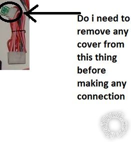
Is there anything to be remove or just leave the way it is and making the connection
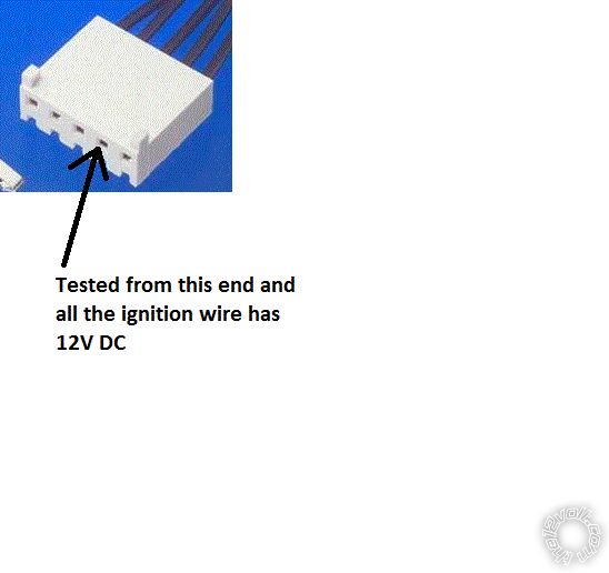
Posted By: cherxiong
Date Posted: March 15, 2015 at 9:30 PM
I removed the connector from the box and tested the wires individually from the connection side and the ones that supposed to be ignition wires already have 12V.
For example:
Posted By: cherxiong
Date Posted: March 15, 2015 at 9:53 PM
I used the learning TAch with the key start. Does it make any difference. Because the Virtual TAch require a remote start which you can't really do it if your remote has not been paired with your starter.
Posted By: tedmond
Date Posted: March 15, 2015 at 11:33 PM
If you have 12v on the connector side, your wiring at the ignition is wrong.
-------------
Ted
2nd Year Tier 1 Medical School
Still installing as a hobby...pays for groceries
Compustar Expert
Posted By: cherxiong
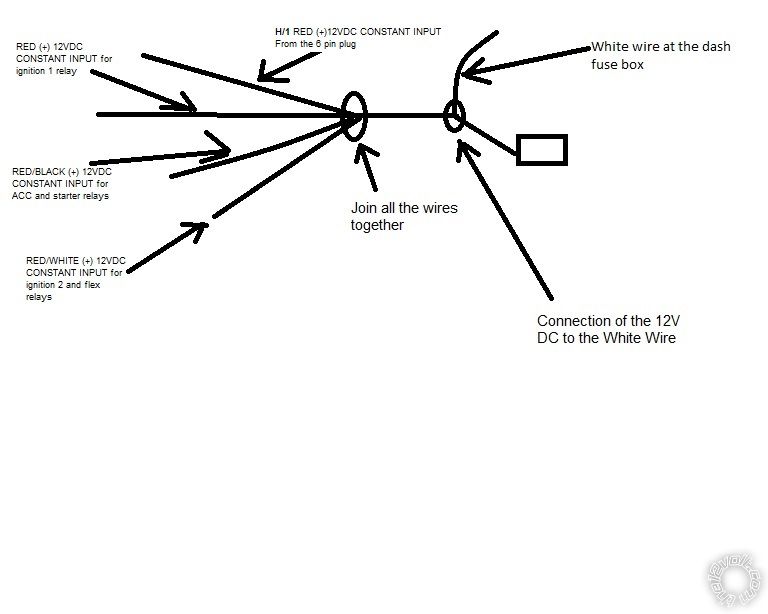
Date Posted: March 16, 2015 at 5:58 AM
I combine all the 12V DC wire together before connecting to the white wire at the dash fuse box as below: Look to see and let me know if this connection create a problem.
Posted By: cherxiong
Date Posted: March 16, 2015 at 6:07 AM
I saw this guy post here had the same configure like my car at the switch
Mike M2
Platinum
Platinum
spacespace
Joined: June 29, 2005
Location:
United States
Posts: 2,653
Posted: March 10, 2008 at 2:25 PM - IP Logged
Strange they are different! Here's what i got today...
12volt- white and yellow @ switch
Ignition1- white @ switch
Ignition2- gray @ switch
Accessory- black @ switch
Starter- white(terminal with 2 wires in it @switch
Posted By: cherxiong
Date Posted: March 16, 2015 at 6:28 AM
My only concern is the Keysense- blue (at the key switch), which I connected with (Pin 5 DARK BLUE (-) 200mA STATUS OUTPUT from the Viper 24 pin plug). If this is right, then I am at the dead end.
I also use wrapping instead of soldering, that might not give me enough voltage?
Posted By: tedmond
Date Posted: March 16, 2015 at 6:28 AM
Post a picture of your ignition wiresat the switch and it's connections from the viper
-------------
Ted
2nd Year Tier 1 Medical School
Still installing as a hobby...pays for groceries
Compustar Expert
Posted By: cherxiong
Date Posted: March 16, 2015 at 7:04 AM
Okay. Will take picture tonight and post it.
Posted By: smokeman1
Date Posted: March 16, 2015 at 9:58 AM
Your car is certainly a puzzler.
Did the DB-ALL2 complete the programming for Type 1 Installation? All four steps?
On page 9 your listing for TX & RX appear to be reversed.
Pin 10 TX Yellow/Black from the DBALL should go to Pin 5 Green
Pin 11 RX ORANGE / Black from the DBALL should go to Pin 4 Pink
Then follow the programing steps on page 19. It must program correctly, or it won't work.
Your immobilizer wiring shows as NUMMI. Refer back to page 7.
-------------
When all else fails, Read the Instructions
Support the12volt.com Make a Donation
Posted By: howie ll
Date Posted: March 16, 2015 at 10:19 AM
Cherxiong I want you to answer me with a checked list.
1) Red, RED / white and RED / black at H3, red at H1 all connected to the thick white at BCM?
2) Do a voltage test between the above terminals on the plugs and your ground point.
Should read 12.3 to 12.5 on your DMM.
3) Is the BLACK/ white on H2 connected to ground? Again measure between the BLACK/ white and red at H1 with your DMM, should be 12-12.5 volts.
4) Have you successfully programmed for:-
a) Tach
b) Automatic
c) Tachometer sense.
d) DB-ALL2
5) From H3
a) Pink to ignition?
b) Pink/white to second ignition?
c) Violet (purple) to starter?
d) Orange to ACC?
Make sure the above group aren't touching each other, e.g. sliver of wire.
How have you connected the joints?
-------------
Amateurs assume, don't test and have problems; pros test first. I am not a free install service.
Read the installation manual, do a search here or online for your vehicle wiring before posting.
Posted By: cherxiong
Date Posted: March 16, 2015 at 10:20 AM
Smokeman.
I flashed the DB-All2 with the xkloader through Xpresskit.com/Directechs.com using express VIP 4.5. Followed all the step for type installation type 1 and also connecting the dball in order as page 19 and program correctly.
I will check page 7 again you mentioned again, but that's for type 2a, not sure if it applies to my vehicle.
Thanks
Posted By: cherxiong
Date Posted: March 16, 2015 at 10:23 AM
I should connect all my constant to the key switch to see if it makes any difference. Because the diagram for Type one is directed to connect to the key switch connector.
Posted By: howie ll
Date Posted: March 16, 2015 at 10:25 AM
Easier to go to white at fusebox or white (could be black at BCM).
Did you use thinner gauge cable like I suggested much neater.
-------------
Amateurs assume, don't test and have problems; pros test first. I am not a free install service.
Read the installation manual, do a search here or online for your vehicle wiring before posting.
Posted By: cherxiong
Date Posted: March 16, 2015 at 10:27 AM
Howeii,
I will print your check list and get the answer for you if I have time to go back to look at my car today.
Thanks
Posted By: smokeman1
Date Posted: March 16, 2015 at 10:32 AM
NOT page 7 of the DBALL install guide, Page 7 of this thread referring to NUMMI vs TMMC made corolla
Your TX & RX appear to be reversed per your listing of wired connections.
-------------
When all else fails, Read the Instructions
Support the12volt.com Make a Donation
Posted By: cherxiong
Date Posted: March 16, 2015 at 10:42 AM
Smokeman,
I am not so sure, but my VIN number started with a "J". I had taken the car for oil change and recalls repair. Dealer said it's a Japanese made.
Posted By: cherxiong
Date Posted: March 16, 2015 at 10:47 AM
Smokeman. I will go check the "TX & RX appear to be reversed per your listing of wired connections." again to make sure that i list it right and not reverse.
Thanks.
Posted By: howie ll
Date Posted: March 16, 2015 at 10:49 AM
If they were wrong surely you won't get the green light on the DB-ALL?
Hence my check list request.
-------------
Amateurs assume, don't test and have problems; pros test first. I am not a free install service.
Read the installation manual, do a search here or online for your vehicle wiring before posting.
Posted By: cherxiong
Date Posted: March 16, 2015 at 10:51 AM
Howeii...
howie ll wrote:
Easier to go to white at fusebox or white (could be black at BCM).
Did you use thinner gauge cable like I suggested much neater.
No. I didn't want to mess around with it too much, so I just strip the original wire and hook to the white wire at the fuse box.
Posted By: cherxiong
Date Posted: March 16, 2015 at 10:52 AM
Yea, i do have a green light on the DBALL
Posted By: howie ll
Date Posted: March 16, 2015 at 10:54 AM
Hook? Define because you might be shorting constant to ignition.
-------------
Amateurs assume, don't test and have problems; pros test first. I am not a free install service.
Read the installation manual, do a search here or online for your vehicle wiring before posting.
Posted By: cherxiong
Date Posted: March 16, 2015 at 11:01 AM
I used the wrapping method (hook). Wrap the wire around one side then the other and finally around itself. Following bulldog method: https://www.bulldogsecurity.com/pdf/modelsrs82_85.pdf
Posted By: howie ll
Date Posted: March 16, 2015 at 11:02 AM
You should then solder the joint and use Scotch 33+ to seal it.
-------------
Amateurs assume, don't test and have problems; pros test first. I am not a free install service.
Read the installation manual, do a search here or online for your vehicle wiring before posting.
Posted By: cherxiong
Date Posted: March 16, 2015 at 11:02 AM
Then taping the wire with electrical tape
Posted By: howie ll
Date Posted: March 16, 2015 at 11:04 AM
We crossed posts, SOLDER, makes a more conductive and secure joint.
-------------
Amateurs assume, don't test and have problems; pros test first. I am not a free install service.
Read the installation manual, do a search here or online for your vehicle wiring before posting.
Posted By: cherxiong
Date Posted: March 16, 2015 at 11:05 AM
Howei II
Yea. The only thing left is soldering to see if it make a difference as of right now
Posted By: cherxiong
Date Posted: March 16, 2015 at 11:09 AM
Just curious, I don't need to put any key in the bypass module or the remote starter right? for this installation.
Posted By: howie ll
Date Posted: March 16, 2015 at 11:13 AM
No.
-------------
Amateurs assume, don't test and have problems; pros test first. I am not a free install service.
Read the installation manual, do a search here or online for your vehicle wiring before posting.
Posted By: cherxiong
Date Posted: March 16, 2015 at 11:16 AM
I am not a solderer, that's why I pick the wrapping method. but I will try to do it this week. I just can't imagine de-soldering if thing doesn't go right
Posted By: smokeman1
Date Posted: March 16, 2015 at 11:20 AM
Again I ask for an entire listing of ALL connection from what to what.
Viper 4706 and the DBALL
This shouldn't be this difficult of an install.
You might be missing something that if you list all of your connections, we might be able to "see it"
-------------
When all else fails, Read the Instructions
Support the12volt.com Make a Donation
Posted By: howie ll
Date Posted: March 16, 2015 at 11:23 AM
Ignition 2 or the red primaries at H3 not connected, or poor ground hence asking for the check list.
-------------
Amateurs assume, don't test and have problems; pros test first. I am not a free install service.
Read the installation manual, do a search here or online for your vehicle wiring before posting.
Posted By: cherxiong
Date Posted: March 16, 2015 at 11:25 AM
Smokeman,
I listed yesterday on page 9 after you asked me. Please help me check.
Thanks
Posted By: howie ll
Date Posted: March 16, 2015 at 11:34 AM
ALL of your connections please.
-------------
Amateurs assume, don't test and have problems; pros test first. I am not a free install service.
Read the installation manual, do a search here or online for your vehicle wiring before posting.
Posted By: cherxiong
Date Posted: March 16, 2015 at 11:40 AM
That's everything i have connected.
I used the 8 pin connectors from Viper, and 6 Pin connectors from Viper. Then the DBALL to the Remote starter. All listed on page 9.
The only wire that was not there is the Pin 5 Dark Blue Wire from the 24 pin connector connecting to the key sense blue wire at the key switch two pin plug.
Posted By: howie ll
Date Posted: March 16, 2015 at 11:42 AM
Or the grounded BLACK/ white from H2?
-------------
Amateurs assume, don't test and have problems; pros test first. I am not a free install service.
Read the installation manual, do a search here or online for your vehicle wiring before posting.
Posted By: cherxiong
Date Posted: March 16, 2015 at 11:42 AM
I know, I thought it would be easy too. I should do wire to wire connection instead of D2D connection.
Posted By: howie ll
Date Posted: March 16, 2015 at 11:44 AM
No D2D works perfectly well with a DB-ALL 2
-------------
Amateurs assume, don't test and have problems; pros test first. I am not a free install service.
Read the installation manual, do a search here or online for your vehicle wiring before posting.
Posted By: cherxiong
Date Posted: March 16, 2015 at 11:47 AM
Howie II.
The only ground wire I haven't used was the one from the 24 pin connector.
Listing as:
13 BLACK/ WHITE*** (-) NEUTRAL SAFETY /PARKING BRAKE INPUT
Posted By: cherxiong
Date Posted: March 16, 2015 at 11:49 AM
*** Ground this wire for automatic transmission vehicles or connect to the parking
brake wire for manual transmission vehicles (see owners guide for manual
transmission procedure).
Posted By: howie ll
Date Posted: March 16, 2015 at 11:50 AM
And that's your answer right there.
That's why I wanted you to follow my check list. I find quite often using DB-ALL2 that some things you have to hardwire.
-------------
Amateurs assume, don't test and have problems; pros test first. I am not a free install service.
Read the installation manual, do a search here or online for your vehicle wiring before posting.
Posted By: howie ll
Date Posted: March 16, 2015 at 11:52 AM
BTW, Smokeman and myself mentioned the BLACK/ white at least three times.
And BTW Corollas are made in Japan, China, India, the US, S.America and Turkey which makes Corollas for the Middle East and the similar "Auris" for Western Europe.
And they are all the same!
-------------
Amateurs assume, don't test and have problems; pros test first. I am not a free install service.
Read the installation manual, do a search here or online for your vehicle wiring before posting.
Posted By: tedmond
Date Posted: March 16, 2015 at 11:53 AM
cherxiong wrote:
*** Ground this wire for automatic transmission vehicles or connect to the parking
brake wire for manual transmission vehicles (see owners guide for manual
transmission procedure).
you have to ground this wire. If you read back a few pages your 8 start error was due to your neutral safety. Myself, and 3 others pointed it out. ------------- Ted
2nd Year Tier 1 Medical School
Still installing as a hobby...pays for groceries
Compustar Expert
Posted By: cherxiong
Date Posted: March 16, 2015 at 11:53 AM
Okay, I will ground that tonight and let you guys know.
Posted By: howie ll
Date Posted: March 16, 2015 at 11:55 AM
Now do you see why I wanted you to do a check/test list?
-------------
Amateurs assume, don't test and have problems; pros test first. I am not a free install service.
Read the installation manual, do a search here or online for your vehicle wiring before posting.
Posted By: cherxiong
Date Posted: March 16, 2015 at 11:56 AM
Ted,
I know. But it doesn't show in the diagram. The one showed in the diagram, which is the Black Wire from the 6 pin connector and has been grounded.
Posted By: howie ll
Date Posted: March 16, 2015 at 12:10 PM
Let me refer you back to page 7 of this opus.
Q) Now i have the diagnostic as 8 flash :the neutral safety shutdown. I have the neutral safety switch on the on position as of right now. Any suggestion?
And my answer:-
BLACK/ white on the H2 plug should be grounded.
-------------
Amateurs assume, don't test and have problems; pros test first. I am not a free install service.
Read the installation manual, do a search here or online for your vehicle wiring before posting.
Posted By: howie ll
Date Posted: March 16, 2015 at 12:11 PM
We can't help those who don't help themselves. This really is one of the easiest vehicles to do.
-------------
Amateurs assume, don't test and have problems; pros test first. I am not a free install service.
Read the installation manual, do a search here or online for your vehicle wiring before posting.
Posted By: cherxiong
Date Posted: March 16, 2015 at 12:15 PM
Any other wire that need to be connected from the connector bellow. I will connect everything tonight if possible.
Posted By: cherxiong
Date Posted: March 16, 2015 at 12:16 PM
Sorry Howeii,
I think if it doesn't show on the diagram then the D2D should take care of everything already.
Posted By: smokeman1
Date Posted: March 16, 2015 at 12:22 PM
The D2D takes care of the Ground for the power to the DB-ALL.
Not the ground for the Viper unit OR the BLACK/ White Safety ground. If an automatic transmission BLACK/ White MUST BE GROUNDED. Along with the black ground from the 6 pin harness.
-------------
When all else fails, Read the Instructions
Support the12volt.com Make a Donation
Posted By: cherxiong
Date Posted: March 16, 2015 at 12:27 PM
Thanks. I owe you guys each a shot of Blue Label if it works. : ) )
Posted By: howie ll
Date Posted: March 16, 2015 at 12:37 PM
Dark blue status wire to keysense unless DB-ALL2 does it.
Don't drink, mines a carton of Kent deluxe (if still sold in the US) or Marlboro light 100's
 ------------- Amateurs assume, don't test and have problems; pros test first. I am not a free install service.
Read the installation manual, do a search here or online for your vehicle wiring before posting.
Posted By: tedmond
Date Posted: March 16, 2015 at 12:54 PM
smokeman1 wrote:
The D2D takes care of the Ground for the power to the DB-ALL.
Not the ground for the Viper unit OR the BLACK/ White Safety ground. If an automatic transmission BLACK/ White MUST BE GROUNDED. Along with the black ground from the 6 pin harness.
 ------------- Ted
2nd Year Tier 1 Medical School
Still installing as a hobby...pays for groceries
Compustar Expert
Posted By: cherxiong
Date Posted: March 16, 2015 at 12:55 PM
Posted By: cherxiong
Date Posted: March 16, 2015 at 12:57 PM
Thanks to all. Working or not I am very happy with all the efforts to help me out. Impressed!!!!!!!!!!!!!!!!!!!!!!!!!!!!!!!!!
Posted By: cherxiong
Date Posted: March 16, 2015 at 7:37 PM
Thanks all.....It works after I grounded the BLACK/ White wire. I didn't change any connection that I have made on page 9. I didn't have to have the key sense connected to the dark blue wire, Howeii...Thanks for helping from the beginning to the end.
Thank you to Tedmond, Smokeman for trying so hard to help amateur like me.
A little donation has made to the 12Volts as promissed.
Thanks.
Posted By: smokeman1
Date Posted: March 16, 2015 at 7:57 PM
OUTSTANDING!!
-------------
When all else fails, Read the Instructions
Support the12volt.com Make a Donation
Posted By: cherxiong
Date Posted: March 16, 2015 at 8:45 PM
If anyone ever comes across this topic. This is a connection of remote starter 4706V (Viper) and Corolla 2009 Japan Made. The configuration and connection is all summarized on page 9. The only two connection that were not there were the Hood Pin, and the BLACK/ White ground. Connecting these two option and all the connection on page 9 and you should be good to go. Thanks to Tedmond, Smokeman1, and Howei II. They are the expert if you have any question.
Posted By: cherxiong
Date Posted: March 17, 2015 at 6:12 PM
smokeman, Ted, and Howeii,
I went to solder all the wire and now I can't start my car. What is going on. The constant is not at 12V anymore. Please advise
Posted By: cherxiong
Date Posted: March 17, 2015 at 6:12 PM
it only went to around 10V
Posted By: cherxiong
Date Posted: March 17, 2015 at 6:13 PM
Was trying to make it more solid, but worse
Posted By: cherxiong
Date Posted: March 17, 2015 at 6:17 PM
Even the white wire at the dash fuse doesn't show twelve volt
Posted By: smokeman1
Date Posted: March 17, 2015 at 7:11 PM
I would start looking at fuses. See if one is "popped"
Might have to look under the hood for fuses. I take it the White wire you are refering to is the one at the fuse box. Just my guess.
-------------
When all else fails, Read the Instructions
Support the12volt.com Make a Donation
Posted By: cherxiong
Date Posted: March 17, 2015 at 7:52 PM
"Popped" you meant I might need to replace a fuse? And yes, that the white wire I was referring to.
Posted By: cherxiong
Date Posted: March 17, 2015 at 7:54 PM
Did you mean the fuse for the battery is broken, possibly?
Posted By: tedmond
Date Posted: March 17, 2015 at 8:34 PM
look inside the fuse box under the hood. It should say BATTERY its a pretty large 100-150 amp fuse. Not your typical 2 pin fuse. Its a thin rectangle if I'm not mistaken. Pig to pull out though, as the fusebox has to be disassembled.
your soldering iron probably touched ground while soldering.
-------------
Ted
2nd Year Tier 1 Medical School
Still installing as a hobby...pays for groceries
Compustar Expert
Posted By: cherxiong
Date Posted: March 18, 2015 at 5:17 AM
Posted By: cherxiong
Date Posted: March 18, 2015 at 6:12 AM
Before I drive my car out of the parking lot, I want to make sure that it's safe : ). One more important safety question is:
Do I need to connect the Pin 20 Brown (+) Brake Shutdown Input from the 24 pin connector of the remote starter to the Brake Pedal
Posted By: howie ll
Date Posted: March 18, 2015 at 6:16 AM
Test it may be from the DB-ALL.
Effect remote start then push foot brake if it shuts down you're OK.
-------------
Amateurs assume, don't test and have problems; pros test first. I am not a free install service.
Read the installation manual, do a search here or online for your vehicle wiring before posting.
Posted By: cherxiong
Date Posted: March 19, 2015 at 7:30 AM
Awesome. Tested and working. Driving to work today. All safe and sound.
Posted By: cherxiong
Date Posted: May 16, 2015 at 5:41 PM
My starter wont start my car any more. Please help. When remote start, nothing happen. No cranking. The remote control sense that the car has been started, and the timer of the remote control start running, but the car doesn't start. Inside the car, I have Check Engine Light on, Oil Indicator light on, and the Battery light on.
Just change the oil today to make sure that it was not low oil level, but that doesn't help.
Thanks so much
Posted By: howie ll
Date Posted: May 16, 2015 at 5:49 PM
Does it start on the key?
-------------
Amateurs assume, don't test and have problems; pros test first. I am not a free install service.
Read the installation manual, do a search here or online for your vehicle wiring before posting.
Posted By: smokeman1
Date Posted: May 16, 2015 at 6:41 PM
Did you check the fuses?
-------------
When all else fails, Read the Instructions
Support the12volt.com Make a Donation
Posted By: howie ll
Date Posted: May 17, 2015 at 2:22 AM
One small step at a time please Smoke, we both already know the answer ------------- Amateurs assume, don't test and have problems; pros test first. I am not a free install service.
Read the installation manual, do a search here or online for your vehicle wiring before posting.
Posted By: cherxiong
Date Posted: May 17, 2015 at 6:31 AM
hehehe Howeii
Yes. it start with the key.
Which fuse should I check? The one in the dash board or the one that comes with RS?
Posted By: howie ll
Date Posted: May 17, 2015 at 6:34 AM
The THREE with the RS specifically the one on the RED / BLACK H3 wire.
Make sure you're getting 12 Volts at the PURPLE H3 on start.
-------------
Amateurs assume, don't test and have problems; pros test first. I am not a free install service.
Read the installation manual, do a search here or online for your vehicle wiring before posting.
Posted By: cherxiong
Date Posted: May 23, 2015 at 5:14 PM
All the fuses tested today, and all giving 12volts
Posted By: howie ll
Date Posted: May 24, 2015 at 1:58 AM
Use a meter to check continuity or specifically does the violet starter output go to 12V+ during remote start?
Do a shutdown diagnostic test.
-------------
Amateurs assume, don't test and have problems; pros test first. I am not a free install service.
Read the installation manual, do a search here or online for your vehicle wiring before posting.
Posted By: cherxiong
Date Posted: May 24, 2015 at 8:55 AM
Don't know what happened. I went back to the car today and unplugged all the fuses and replugged them back on and it just works again. Wish I know what cause the problem, that way I can solve it in the future if I have this problem again.
Posted By: cherxiong
Date Posted: July 09, 2015 at 9:56 AM
Airbags came off and on for a month now. For both of my car that I have this remote car starter installed. Please help, Howie II and anyone out there.
Thanks
|


