icbm7071 alarm in 2005 Buick Rendezvous
Printed From: the12volt.com
Forum Name: Car Security and Convenience
Forum Discription: Car Alarms, Keyless Entries, Remote Starters, Immobilizer Bypasses, Sensors, Door Locks, Window Modules, Heated Mirrors, Heated Seats, etc.
URL: https://www.the12volt.com/installbay/forum_posts.asp?tid=138840
Printed Date: April 03, 2026 at 11:11 PM
Topic: icbm7071 alarm in 2005 Buick Rendezvous
Posted By: antman1
Subject: icbm7071 alarm in 2005 Buick Rendezvous
Date Posted: April 19, 2015 at 11:52 AM
I have a 2005 Buick Rendezvous and have not found a wiring diagram for this install.
I have purchased the ICBM 7071 and have installed one of these in my other vehicle with the help of the awesome members on this site and was hoping I may be able to get some more help on wiring this up in the 2005 Buick Rendezvous. I am not sure on what wire will go to what. I also just got this vehicle used and it did not come with a key fob so I am not sure if it already has an alarm or key less entry. I am not sure how to tell. If anyone can help me I would really appreciate it. Here is the instruction manual for this alarm. Thank you all in advance.
Here is the link to the manual:
ICBM7071 Manual
If you can help please let me know, Thank you.
Replies:
Posted By: tedmond
Date Posted: April 19, 2015 at 2:51 PM
Since your unit is not compatible in D2D, You will need to follow a w2w connection.
Purchase a bypass module of your choice. I suggest the idatalink ads-alca, but the fortin evo-all works as well. The idatalink will require a flash on it for your vehicle DLGL1, however the fortin would be ready to go out of the box.
https://cdncontent2.idatalink.com/corporate/Content/Manuals/DL-GM1/ADS-AL(DL)-GM1_20111004.pdf
https://fortin.ca/download/12981/evo-all_gm.rev-20140123.pdf
After you have connected the corresponding wires (only connect whats supported in the guide) to the remote start + ignition, ground when running, data to the car etc.
From there you need to power the 12v constant of the remote start to the ignition harness + connect the acc, ign, start wires, run a hood pin and brake shutdown.
-------------
Ted
2nd Year Tier 1 Medical School
Still installing as a hobby...pays for groceries
Compustar Expert
Posted By: antman1
Date Posted: April 19, 2015 at 3:09 PM
So the wiring is pretty straight forward? No relays needed and special things to do for it to work? Thank you for your response.
Posted By: antman1
Date Posted: August 21, 2015 at 1:38 AM
tedmond wrote:
Since your unit is not compatible in D2D, You will need to follow a w2w connection.
Purchase a bypass module of your choice. I suggest the idatalink ads-alca, but the fortin evo-all works as well. The idatalink will require a flash on it for your vehicle DLGL1, however the fortin would be ready to go out of the box.
https://cdncontent2.idatalink.com/corporate/Content/Manuals/DL-GM1/ADS-AL(DL)-GM1_20111004.pdf
https://fortin.ca/download/12981/evo-all_gm.rev-20140123.pdf
After you have connected the corresponding wires (only connect whats supported in the guide) to the remote start + ignition, ground when running, data to the car etc.
From there you need to power the 12v constant of the remote start to the ignition harness + connect the acc, ign, start wires, run a hood pin and brake shutdown.
Would This work for the Bypass module?

Also when you say "Since your unit is not compatible in D2D, You will need to follow a w2w connection." you mean direct Wire to Wire right? And if so does that mean I should not need to add relays and such just connect the wires to the corresponding connections in the car? Thank you again.
Posted By: kreg357
Date Posted: August 21, 2015 at 7:13 AM
Yes, W2W means wire to wire. The ICBM is not capable of D2D communication.
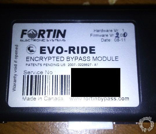
Look at the back of the EVO-ALL for a white sticker. It should denote the important info about the module as it left the factory.
Specifically the H/W version and F/W version. You need F/W version 4.06. If it is something other than that, you will need to get
it re-flashed to the correct 4.06 version. If that is OK, here is a link to the install guide :
https://fortin.ca/download/12981/evo-all_gm.rev-20140123.pdf
You will follow the Connection 3 wiring diagram. All of the gray dashed lines must be connected to the corresponding wire of the
ICBM module ( with the possible exception of the Emergency Brake output and Unlock Driver 2 ). The solid Black wires are
mandatory connections. The EVO-ALL handles the power door locks, trunk release, parking lights, transponder bypass and supplies
the door status, foot brake and Tach signals. Set the ICBM to (-) Parking Light output and configure for (-) door lock outputs.
Here is a list of the cars main ignition wires :
12 VOLT CONSTANT ORANGE (+) @ IGNITION SWITCH HARNESS
STARTER YELLOW (+) @ IGNITION SWITCH HARNESS
IGNITION 1 PINK (+) @ IGNITION SWITCH HARNESS
IGNITION 2 DARK GREEN (+) @ IGNITION SWITCH HARNESS
ACCESSORY /HEATER BLOWER 1 ORANGE (+) @ IGNITION SWITCH HARNESS
ACCESSORY /HEATER BLOWER 2 BROWN (+) @ IGNITION SWITCH HARNESS
The ICBM can directly supply power to all but the Brown ACC2 wire. Leave that un-powered for now. If you have issues, you might
need to power it using an extra 30/40 Amp SPDT relay with fuse.
Your best bet is to make up a nice wiring chart that lists to to / from for all of your proposed connections for the R/S &
the EVO-ALL and post that for member review / input. ------------- Soldering is fun!
Posted By: antman1
Date Posted: August 25, 2015 at 9:42 PM
**EDIT**
I just noticed your post kreg357 as I was trying to post this up. Thank you for your reply. I didnt get an email saying anyone replied. I am going to study how to install the EVO-ALL with the system. I have the EVO-ALL just have to read more into it cause I have never looked into it before. I will try to figure it out and post another with what I found for connecting the unit with the EVO-ALL when I get done studying. It is a learning experience.
So far from what I can tell the EVO-ALL is going to have most all the wiring from the alarm connected to it except those few you mentioned in your post? Also there is a Orange Accessory wire and Orange Constant, Both say at the Ignition Harness. Are they one in the same or will I find 2 different wires?
This EVO-ALL looks like I may be able to do most my wiring outside the car and then connect these wires. I am still gonna study up on it. Thank you so much for replying.
Posted By: antman1
Date Posted: August 25, 2015 at 10:45 PM
Ok, I am not sure what all I may be missing but this is starting to not look too bad to install now. I am not sure on the connections needed from the EVO-ALL to the vehicle so I will need to look at that more. Anyone have a subscription to Wirecolor that might be able to post the diagram for installing the EVO-All in the 2002-2007 Buick Rendezvous?
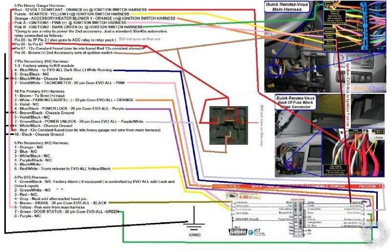
Here is what I have so far.
5 Pin Heavy Gauge Harness:
Red - 12 VOLT CONSTANT - ORANGE (+) @ IGNITION SWITCH HARNESS
Purple - STARTER - YELLOW (+)@ IGNITION SWITCH HARNESS
Orange - ACCESSORY /HEATER BLOWER 1 - ORANGE (+)@ IGNITION SWITCH HARNESS
Pink A - ACCESSORY /HEATER BLOWER 2 - BROWN (+)@ IGNITION SWITCH HARNESS
Pink B - N/C
*Going to use a relay to power the 2nd accessory. Just a standard 30a/40a automotive relay connected as follows:
Pin 85 - Blue/White (-) bypass wire in H4 harness
Pin 86 - ACCESSORY /HEATER BLOWER 1 - Orange Accessory wire from above
Pin 87 - 12v Constant Fused (can tie into fused Red 12v constant above)
Pin 30 - BLACK/ White (+) 2nd Accessory wire at ignition switch
7 Pin Secondary (H4) Harness:
1-3 - Factory wiring to R/S module
4 - Blue/White (See Above)
5 - Gray/Black - N/C
6 - BLACK/ White - Chassis Ground
7 - Violet/White TACHOMETER - 20 pin Conn EVO-ALL PINK
10 Pin Primary (H1) Harness
1 - Brown - To Siren (+) input
2 - White - PARKING LIGHTS ( - ) - 20 pin Conn EVO-ALL ORANGE
3 - Violet - N/C
4 - Blue/Black - POWER LOCK - 20 pin Conn EVO-ALL Purple
5 - BROWN / Black - Chassis Ground
6 - Violet/Black - N/C
7 - GREEN/ Black - POWER UNLOCK - 20 pin Conn EVO-ALL PURPLE / White
8 - WHITE/ Black - Chassis Ground
9 - Red - 12v Constant fused (can tie into heavy gauge red wire from main harness)
10 - Black - Chassis Ground
6 Pin Secondary (H2) Harness:
1 - Orange N/C
2 - Blue - N/C
3 - WHITE/ Black - N/C
4 - PURPLE / Black - N/C
5 - BLACK/ White N/C
6 - RED / White - N/C
8 Pin (H3) Harness:
1 - GREEN/ Black - ?? NOT SURE
2 - GREEN / WHITE - ?? NOT SURE
3 - Red N/C.
4 - Gray - Must add aftermarket hood pin.
5 - Brown BRAKE - 20 pin Conn EVO-ALL BLACK
6 - Yellow - Pink wire from main harness
7 - Green - DOMELIGHT SUPERVISION DOOR STATUS - 20 pin Conn EVO-ALL GREEN
8 - Purple - N/C
Posted By: kreg357
Date Posted: August 27, 2015 at 8:15 AM
Not a brand I use but being as you have 2 of them...
Here are some corrections / suggestions :
5 Pin Heavy Gauge Harness:
Red - 12 VOLT CONSTANT - ORANGE (+) @ IGNITION SWITCH HARNESS
Purple - STARTER - YELLOW (+)@ IGNITION SWITCH HARNESS
Orange - ACCESSORY /HEATER BLOWER 1 - ORANGE (+)@ IGNITION SWITCH HARNESS
Pink A - IGNITION1 - PINK (+) @ IGNITION SWITCH HARNESS
Pink B - IGNITION2 - DARK GREEN (+) @ IGNITION SWITCH HARNESS
*Going to use a relay to power the 2nd accessory. Just a standard 30a/40a automotive relay connected as follows:
Pin 85 - to 7P Pin 2 ( also goes to ACC relay in relay pack )
Pin 86 - to Pin 87
Pin 87 - 12v Constant Fused (can tie into fused Red 12v constant above)
Pin 30 - Brown (+) 2nd Accessory wire at ignition switch
7 Pin Secondary (H4) Harness:
1-3 - Factory wiring to R/S module
4 - Blue/White - to EVO-ALL Dark Blue (-) While Running
5 - Gray/Black - N/C
6 - BLACK/ White - Chassis Ground
7 - Violet/White TACHOMETER - 20 pin Conn EVO-ALL PINK
10 Pin Primary (H1) Harness
1 - Brown - To Siren (+) input
2 - White - PARKING LIGHTS ( - ) - 20 pin Conn EVO-ALL ORANGE
3 - Violet - N/C
4 - Blue/Black - POWER LOCK - 20 pin Conn EVO-ALL Purple
5 - BROWN / Black - Chassis Ground
6 - Violet/Black - N/C
7 - GREEN/ Black - POWER UNLOCK - 20 pin Conn EVO-ALL PURPLE / White
8 - WHITE/ Black - Chassis Ground
9 - Red - 12v Constant fused (can tie into heavy gauge red wire from main harness)
10 - Black - Chassis Ground
6 Pin Secondary (H2) Harness:
1 - Orange N/C
2 - Blue - N/C
3 - WHITE/ Black - N/C
4 - PURPLE / Black - N/C
5 - BLACK/ White to EVO-ALL Pink Tach output ** Program for Tach Mode
6 - RED / White - Trunk release to EVO-ALL Yellow/Black
8 Pin (H3) Harness:
1 - GREEN/ Black - N/C Factory Alarm ( if equipped ) is controlled by EVO-ALL with Lock and Unlock inputs
2 - GREEN / WHITE - N/C " "
3 - Red N/C.
4 - Gray - Must add aftermarket hood pin.
5 - Brown BRAKE - 20 pin Conn EVO-ALL BLACK
6 - Yellow - Pink wire from main harness
7 - Green - DOOR STATUS - 20 pin Conn EVO-ALL GREEN
8 - Purple - N/C ------------- Soldering is fun!
Posted By: antman1
Date Posted: August 27, 2015 at 11:19 AM
Thank you so much. This helps me out a lot. I will start doing my prep on this. I am still not sure how the EVO-ALL connects to the Vehicle for all this though. The EVO-ALL I got was an open box and I dont have the code needed for the website to give me a diagram for my vehicle. I am still working on seeing what I need to do for that part of this.
Posted By: kreg357
Date Posted: August 27, 2015 at 6:18 PM
Download the correct EVO-ALL install guide and follow the Connection 3 wiring. Only one wire to the car, everything else goes to the R/S.
Remember, you need F/W Ver 4.06. Other versions won't work ( according to the install guide ). ------------- Soldering is fun!
Posted By: antman1
Date Posted: August 28, 2015 at 10:10 AM
kreg357 wrote:
Download the correct EVO-ALL install guide and follow the Connection 3 wiring. Only one wire to the car, everything else goes to the R/S.
Remember, you need F/W Ver 4.06. Other versions won't work ( according to the install guide ).
That is incredible. I was expecting it to be like the others I have done but this EVO-ALL pretty much does the most of it. thank you. I had a couple of questions though in the changes you posted.
on 5 Pin Heavy Gauge Harness:
Red - 12 VOLT CONSTANT - ORANGE (+) @ IGNITION SWITCH HARNESS
Orange - ACCESSORY /HEATER BLOWER 1 - ORANGE (+)@ IGNITION SWITCH HARNESS
(These 2 cant be the same Orange wire at the ignition harness are they?)
On the relay:
Pin 85 - to 7P Pin 2 ( also goes to ACC relay in relay pack )
Pin 86 - to Pin 87
Pin 87 - 12v Constant Fused (can tie into fused Red 12v constant above)
Pin 30 - Brown (+) 2nd Accessory wire at ignition switch
(Is Pin 86 going to loop to pin 87? and on Pin 85 I am not sure on which one is "7P Pin 2 and the ACC relay wire" and I may have made an error on Pin 30. Not sure what wire to connect for the spot I put Brown (+) 2nd accessory wire at ignition switch)
on 6 Pin Secondary (H2) Harness:
5 - BLACK/ White to EVO-ALL Pink Tach output ** Program for Tach Mode
(this BLACK/ White wire is for "Dome Light Output (-)500 mA" and it is saying to have that go to Tach Wire on the EVO-ALL. I have Violet/White wire from the H4 harness for the tach signal)
Posted By: kreg357
Date Posted: August 28, 2015 at 2:08 PM
Here is a link to the ReadyRemote site for the wiring guide plus photo's of the wires : https://www.readyremote.com/main.asp
They have a very nice photo of the ignition harness connector.
Point 1
on 5 Pin Heavy Gauge Harness:
Red - 12 VOLT CONSTANT - ORANGE (+) @ IGNITION SWITCH HARNESS
Orange - ACCESSORY /HEATER BLOWER 1 - ORANGE (+)@ IGNITION SWITCH HARNESS
(These 2 cant be the same Orange wire at the ignition harness are they?)
Please use the ReadyRemote link posted above to assist in finding the correct ignition wires. As a basic GM product you will find :
Ignition 1 = Pink
Ignition 2 = Dark Green ( most other GM's have a White IGN2 wire )
Accessory 1 = Orange
Accessory 2 = Brown
Starter = Yellow
While there might be many wires in that area. Testing and referring to the photo will identify the correct wires for the ICBM connections.
Point 2
On the relay:
Pin 85 - to 7P Pin 2 ( also goes to ACC relay in relay pack )
Pin 86 - to Pin 87
Pin 87 - 12v Constant Fused (can tie into fused Red 12v constant above)
Pin 30 - Brown (+) 2nd Accessory wire at ignition switch
(Is Pin 86 going to loop to pin 87? and on Pin 85 I am not sure on which one is "7P Pin 2 and the ACC relay wire" and I may have made
an error on Pin 30. Not sure what wire to connect for the spot I put Brown (+) 2nd accessory wire at ignition switch)
The relay is for the car's Accessory 2 wire. This wire is Brown. I changed the relay wiring slightly because I didn't want to use the
(-) GWR signal for both the relay and the EVO-ALL. In my mind the EVO-ALL has priority and the ICBM only has one GWR output.
Yes, Pin 86 and 87 get tied together. Use a meter to check the 7P Pin 2 wire that controls the ACC1 relay to verify that it is a (-) signal
and tap into that for the ACC2 relay control.
Point 3
on 6 Pin Secondary (H2) Harness:
5 - BLACK/ White to EVO-ALL Pink Tach output ** Program for Tach Mode
(this BLACK/ White wire is for "Dome Light Output (-)500 mA" and it is saying to have that go to Tach Wire on the EVO-ALL. I have
Violet/White wire from the H4 harness for the tach signal)
You could be correct here. I don't have an install guide for the ICBM unit and am trying to use the diagram in the link you supplied.
I can't see it very well. There is a wire called Oil Pressure Switch / Tach. Connect the EVO-ALL's Tach output to that. From prior
posts on ICBM units, this is where some of your problems will occur. The basic rule of thumb is " Stay away from any R/S system
that uses an Oil Pressure Switch input." ------------- Soldering is fun!
Posted By: antman1
Date Posted: August 31, 2015 at 11:23 AM
I was going to begin this wiring today and just now noticed that I dont think I have the correct firmware from what I see. I was wondering if maybe BestBuys install bay or some place might be able to program it? I might have to buy the FlashLink if not. I actually think I have the wrong thing and will have to get the EVO-ALL.
**EDIT** Well it turns out I am a goofball for sure. This is not the EVO-ALL as I should have clearly seen on the device. I will have to order the right one. I guess I will need to sell this one off to someone.
Posted By: kreg357
Date Posted: August 31, 2015 at 9:14 PM
Yes, that is the wrong module. You need the EVO-ALL.
-------------
Soldering is fun!
Posted By: antman1
Date Posted: September 02, 2015 at 12:05 AM
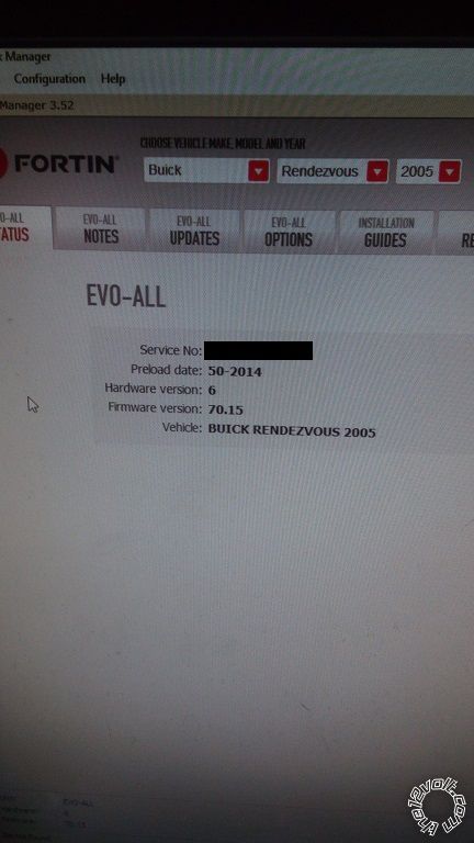
I ordered the EVO-ALL. The unit is Hardware V8 and flashed to Firmware 6.73.14, I assume that will work ok that it is flashed to a newer firmware than version 4.06. I should have it on Friday and I will do my wiring and post a pic of my prep.
Posted By: kreg357
Date Posted: September 02, 2015 at 3:13 AM
Well, you are getting closer. The EVO-ALL is the module you need. However, the 6.73.14 firmware is for Honda products and will
not work on your older Buick vehicle.
Here is the long story. The EVO-ALL was originally like other Fortin modules in the fact that it could support all vehicles with just one
firmware loaded. This pre-loaded, ready to go right out of the box module was a big plus for installers. At a certain point a decision
was made ( due to memory space limitations ), to split-up the firmware for each different vehicle brand / manufacturer. This happened
around Ver 4.06. At Ver 4.07 the old GM / Chrysler J1850 support was dropped. Basically, for your vehicle, Ver 4.06 will work but
anything newer, like Ver 4.09, won't. After the F/W split, Ver 6.70.xx was for GM products but Ver 6.70 still wouldn't support the older
J1850 vehicles until Ver 6.70.11 when J1850 was added back in. Ver 6.71.xx is for Ford, 6.72 is for Nissan, Ver 6.73 is for Honda,
Ver 6.74 is for Chrysler, etc... ( This little bit of Fortin history / knowledge is why +12V Dealers / Installers charge the prices they do
and why most all bypass module manufacturers do not directly support DIY'ers.)
Anyway, for the EVO-ALL to work properly on your 2005 Buick Rendezvous, you need either F/W Ver 4.06 or the current GM F/W,
Ver 6.70.15 ( actually 6.70.11 and up ). You will need to find a place that will re-flash your module. You can do it yourself, if you have
the ~$50 Fortin FlashLink-2 USB cable. ------------- Soldering is fun!
Posted By: antman1
Date Posted: September 03, 2015 at 7:47 PM
thank you. I will see if I can find someone to help me on flashing it. I may have to get the Flashlink cable. This really helped me to understand how it all works though.
Posted By: antman1
Date Posted: September 04, 2015 at 6:28 PM
well this has been an adventurous day and journey. I got my EVO-ALL today and checked with several car audio and alarm places and some tilted their heads and said "Whats that"? While others said "I dont have that but if I did it would be $85 to flash it so you might as well by this module we carry for $79". lol. I will just have to wait a little longer and order the Flash Link v2 programmer.
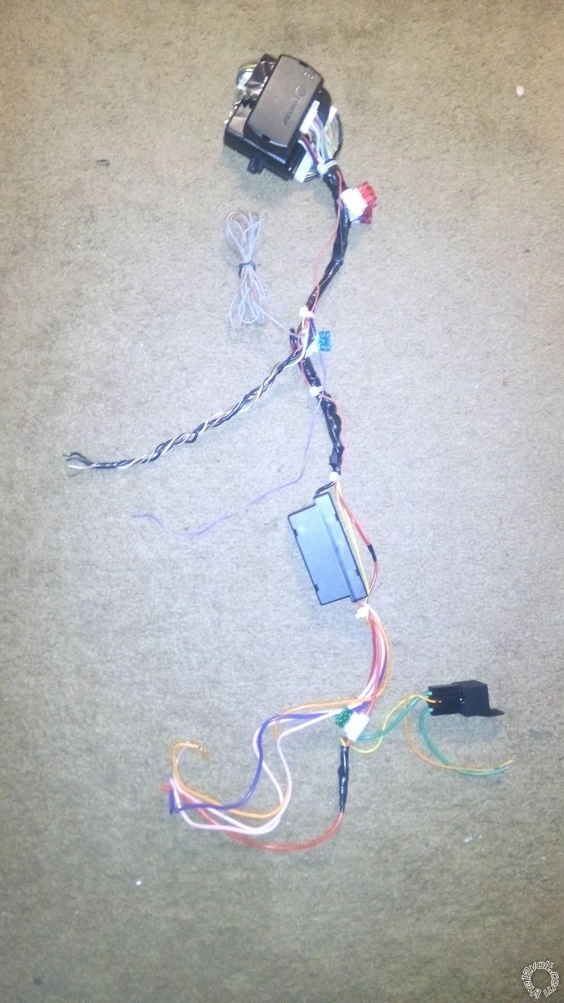
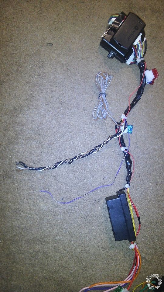
In the mean time I dont see why I couldnt go ahead and do my prep and soldering of the EVO-ALL to the ICBM 7071 so I can just install it to the car after I program it. When I get done I will post pics and stuff to make sure it looks good. Thanks again.
Posted By: kreg357
Date Posted: September 04, 2015 at 9:47 PM
Too bad I don't live closer, I would flash it for you...
Good plan to do the bench prep first. Might want to post your planned wiring for forum members to review and post suggestions. ------------- Soldering is fun!
Posted By: antman1
Date Posted: September 05, 2015 at 12:28 AM
Here is what I have so far. I am not sure on the connection for the relay on Pin 85 still. I got confused again when looking at how everything will go.
Posted By: antman1
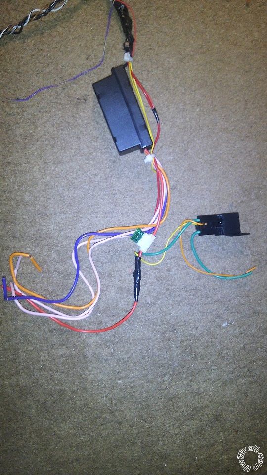
Date Posted: September 06, 2015 at 5:29 PM
Should I connect pin 85 of the relay to the Orange Accessory wire on the heavy main harness? And pin 30 of the relay is just going to go to the Accessory 2 wire on the ignition harness?
Also I was wondering how the EVO-ALL is going to get power? I see the Ignition wire that I am connecting to Ignition 1 on the main harness (I think that is right?), but I dont see a 12v or ground connection.. only the wires to the alarm and the Ignition and OBD2 connection. Am I missing anything there? I will post a pic of my prep I have done when I get back. going for a walk with the kids and will add it to this post as an edit.
Posted By: antman1
Date Posted: September 07, 2015 at 1:54 AM
Posted By: antman1
Date Posted: September 08, 2015 at 12:10 AM
I got all the prep work done. I just put pin 85 from the relay on the Blue/White wire that the EVO-ALL is also using. I dont think it would be a problem.
Now I am just waiting for the Flashlink v2 so I can program it. Hopefully all goes well after that and it will be all done.
Posted By: kreg357
Date Posted: September 08, 2015 at 7:18 AM
The external ACC2 relay will be ON as soon as the R/S unit brings up the GWR signal, signifying a remote start is initiated. As such,
it will not drop the ACC2 output during cranking as is normal when the car is started with the key. Please take a look at the control
wires going from the R/S unit to the satellite relay pack. There is a wire in there that was mentioned earlier that will give you the proper
(-) Accessory relay control signal. That is the control wire I would use for the ACC2 relay.
-------------
Soldering is fun!
Posted By: antman1
Date Posted: September 08, 2015 at 9:40 AM
I will check that but wouldn't it work just as well if I used the Orange Accessory wire on pin 86 like I did in the past versions of this and still used the Blue/White?
Pin 85 - Blue/White (-) bypass wire in H4 harness and EVO-ALL
Pin 86 - Orange Accessory wire from above
Pin 87 - 12v Constant Fused
Pin 30 - Brown (+) 2nd Accessory wire at ignition switch
Then it would only work at the same time as the first accessory wire instead of having 12v constant.
**EDIT**
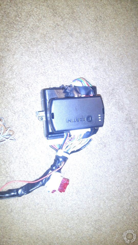
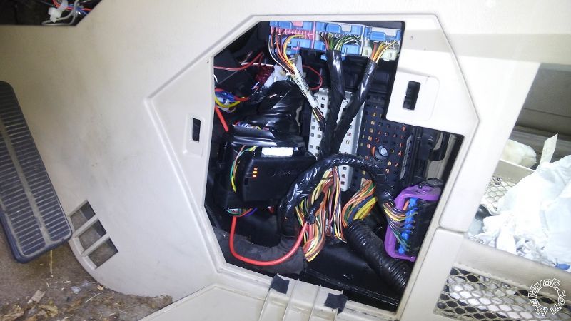
Got me a whole new problem I havent run into on other ICBM 7071s' until now. The Alarm is supposed to have a Jumper "JC2" that changes the "Light Flash Output" from positive or negative. By default (According to the Manual) it is Positive. I had this jumper on my alarm unit in the past and was able to change it to Negative on my Town and Country but on this alarm (same model) it is missing. no jumper. I called the number and spoke with a person that said they dont know technical details and that I need to read the manual more and they will send me another copy in case the manual I have is older. Looks like I may need to convert the Positive to Negative somehow (maybe a relay)? Tech support from there site sent the exact same manual to me I already have saying to change "JC2" jumper.
Here is what the Brain looked like inside. I dont see a jumper, the red jumper wire is for Automatic or Manual transmissions:
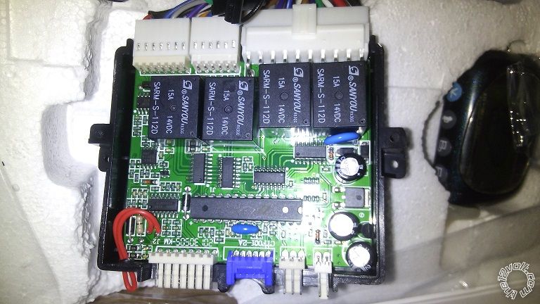
If I cant find a way to make the ICBM7071 use the Negative polarity for the "Light Flash Output" I guess I would have to wire this up, right?
Posted By: kreg357
Date Posted: September 08, 2015 at 8:00 PM
I will check that but wouldn't it work just as well if I used the Orange Accessory wire on pin 86 like I did in the past versions of this and
still used the Blue/White?
Pin 85 - Blue/White (-) bypass wire in H4 harness and EVO-ALL
Pin 86 - Orange Accessory wire from above
Pin 87 - 12v Constant Fused
Pin 30 - Brown (+) 2nd Accessory wire at ignition switch
Then it would only work at the same time as the first accessory wire instead of having 12v constant.
The only issue I have with the above relay wiring is sharing the Blue/White (-) GWR signal between a relay coil and the EVO-ALL.
It would be nice if there were two GWR signal available. In reality, you might not even need to power the Brown ACC2 wire during a
remote start. The Brown ACC2 might only supply power to non-critical things like the radio, wipers, power windows, etc.
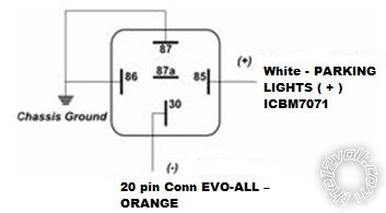
The relay for the Parking Light polarity conversion is OK. You could skip using the EVO-ALL to control the Parking Lights and go
direct to this vehicle wire : Parking Lights (+) Brown (+) @ BCM, gray 24 pin plug, pin B3
Did you get the EVO-ALL re-flashed yet?
------------- Soldering is fun!
Posted By: antman1
Date Posted: September 08, 2015 at 10:34 PM
I havent got the EVO-ALL Reflashed yet. I ordered the Flashlink v2 so I can flash it. waiting on receiving it. Just trying to perfect my prep work on it till then so I can just solder it in and be good to go.
I think I am going to use another relay and still let the EVO-ALL control the Parking lights. I think it is weird this ICBM7071 looks different inside. It is like they changed the board layout and did away with the jumper. Another thing I noticed was different from the other 2 I did is that this one has a Shock sensor separate from the antenna. The other 2 I did had the shock sensor in the Antenna. The manual doesn't account for that either.
Posted By: kreg357
Date Posted: September 09, 2015 at 2:23 AM
Having a selectable Parking Light output is a nice feature, but not insurmountable. Hopefully the updated PCB provides other benefits that make up for this change. Poor / inaccurate documentation is very common on these "off-shore" brands. ------------- Soldering is fun!
Posted By: antman1
Date Posted: September 15, 2015 at 11:02 AM
got the Flash Link today and when I selected my vehicle it recommended firmware 70.15 version. I flashed it to my EVO-ALL. Is that the right firmware as far as the latest and greatest or should I select 4.06 and just flash it instead?
Posted By: kreg357
Date Posted: September 15, 2015 at 6:19 PM
The Fortin recommended 70.15 should be fine. Anything above 70.10, I think will work, as will as the older Ver 4.06.
-------------
Soldering is fun!
Posted By: antman1
Date Posted: September 24, 2015 at 6:34 AM
sorry haven't reported anything back on this. been waiting for a relay and am swamped with work and personal family issues now. I did notice yesterday the Mercury Hood pin switch I got appears broken and the mercury is outside the little glass tube inside it so I had to inform the people I got it from but that shouldn't stop me from completing the install. I will let you know how this goes when I get it completed.
Posted By: antman1
Date Posted: September 26, 2015 at 4:38 PM
Well. I finally got to it today and installed the evo-all and icbm7071 and it was messed up. The door locks locked when I disarmed the alarm and unlocked when I armed the alarm. I checked the wiring again and it was right. I swapped the lock and unlock wires on the evo to the alarm and now it locks when armed. And unlocks when disarmed. I was getting the remote start to crank the car but wasn't staying cranked like it couldn't get the tach signal. I will have to work on it later though. It also seems like the accessories weren't turning on also. I got alarm and keyless entry for now though. Sucks though. Seems the icbm7071 was redesigned and diagram is wrong. Last one I buy now.
I am also wondering if there is something I am missing with the EVO-ALL as far as programming? I flashed version 4.06 to it though just so I could make sure that wasn't the issue. Other times I installed this alarm in my other vehicles it was great. This is the first time it has given me issues.
If I connect the BLACK/ White wire on the ICBM7071 that says "Oil Sensor Input/Generator Input" to a +12v constant would that work to bypass Tach signal needs?
Posted By: antman1
Date Posted: September 29, 2015 at 10:23 AM
I was just thinking about something. The alarm appears to be working for keyless entry and such. but remote start doesnt work. I see the dash lights come on and then it looks like it is going to turn the engine over and the dash lights go out and then the alarm tries again. after the 3rd time it stops trying like it is supposed to do.
I was wondering if maybe the Ground wire I did might be the whole issue. if the ground isnt very good would that be the symptoms of this issue?
Also If I connect the BLACK/ White wire on the ICBM7071 that says "Oil Sensor Input/Generator Input" to a +12v constant would that work to bypass Tach signal needs?
Posted By: antman1
Date Posted: October 01, 2015 at 11:11 AM
now I have a problem with my car. I got home and turned the car off and it said my door was open on the alarm so I went back out to the car and cranked it and it worked fine. I turned it off and went to turn it back on and all power went off and nothing. it was dead. I pulled the power cable off the little box with fuses under the hood and put it back on and the ignition showed lights then I tried to crank it and all lights died again and nothing. I pulled the cover off the fuse box and moved the box and wires around a little and it got lights again and power then I tried to crank and dead again. I disconnected my connections for the alarm and still same thing. Any ideas on what could be causing this?
**UPDATE**
I think I found the issue. Not sure what I may need to do to fix it or even how to replace this. here is a pic of it:
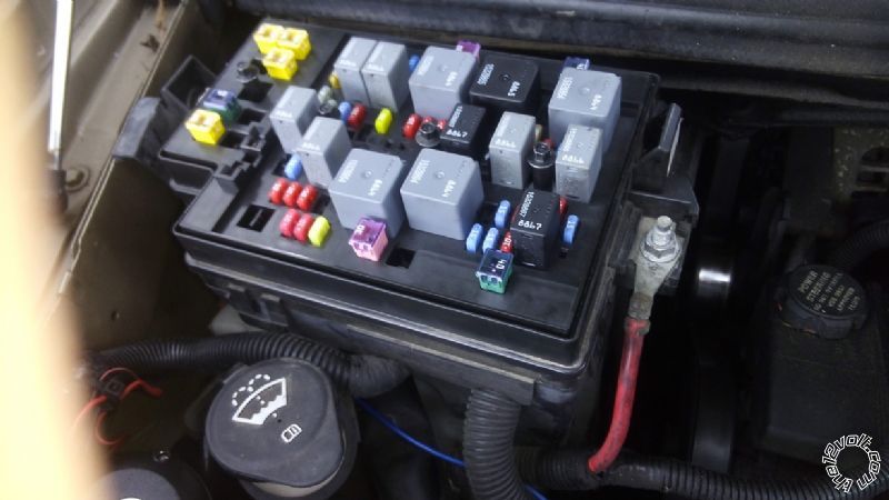
Here is what it is doing on this video and why I believe this is the problem. It seems that the battery terminal connection isnt making good contact anymore. I have the connection tight but makes no difference. If I keep pressure on the cable on the box I can get it started too. Wish I would have found this before I disconnected all the Ignition wires and stuff from the alarm. :(
Video of clicking when I move the battery cable
Posted By: antman1
Date Posted: October 04, 2015 at 9:38 PM
Looks like the issue has to do with a bad connection from fuse box to battery. Having a hard time finding it so I am going to take it to the shop. I did away with my accessory 2 wire I was going to use with a relay because it is not needed. My remote start cranks the car then acts like it isn't getting a tach signal and turns off. I am wondering if the evo-all needs to be programmed to send a tach signal to the alarm? I have it all wired up per my prep. The lock and unlock and lights are all working through the evo-all with no problems. Not sure if it is sending the brake signal either. Do I need to hook the evo-all up to the PC and adjust the settings?
Posted By: antman1
Date Posted: October 10, 2015 at 10:11 PM
Got my car back today. They said there was some loose wires under the hood that the fixed and all is good now. Also was informed my fuel line was leaking and they fixed that so I am lucky I didn't blow up. Unfortunately someone stole my license plate from the car in there lot so I gotta get a new one. But back to my remote start issues. I am wondering if the EVO-ALL needs something else programmed to make it send a tach signal to the alarm or something. Anyone have knowledge on EVO-ALL that can tell me if I missed something? I will hook up to the evo-all tomorrow to check it out. I may just have to run a tach wire and brake wire myself and bypass that part of the evo all if I cant get it to work.
Posted By: antman1
Date Posted: October 11, 2015 at 5:52 PM
Got my remote start on the alarm working now. had to run the same wire for tach to a 12v constant and that worked because it said I could use a tach signal or 12v constant instead. I installed the brain in the center area of the car console. Thank you to all that helped. Now I guess I will sell the Fortin Flash Link Programmer.
Posted By: kreg357
Date Posted: October 11, 2015 at 6:26 PM
Install looks good and clean!
That's the general consensus, the off-shore R/S units always have issues with the Tach. Think it was Howie II that coined the phrase...
"If it uses the oil pressure switch to know the engine is running, bin it!" 
Should be able to sell the Fortin FlashLink cable on EBay and get most of the money back. ------------- Soldering is fun!
Posted By: antman1
Date Posted: October 17, 2015 at 4:41 PM
All is going well so far except for an issue sometimes where the alarm thinks the door is open when it isn't and I can go crank the car and turn it off and rearm it and all is fine.
Also I don't like the feature of the radio staying on after remote start is canceled if I don't open and close the door. I am going to replace the factory radio and rewire the power connections I think so the bcm isn't in control of that.
I do have a question about something else though. I was thinking of getting one of those scanner led strips and want to wire it so if comes on when the alarm is active. I need for 12v to be applied to the led strip only when alarm is armed
Posted By: antman1
Date Posted: August 21, 2016 at 11:16 AM
is it safe to assume if I wanted to add the starter kill relay I would use the wire "Pink A - IGNITION1 - PINK (+) @ IGNITION SWITCH HARNESS" to do this?
Posted By: antman1
Date Posted: August 21, 2016 at 1:34 PM
I got it. It is a easier relay to wire up.
Posted By: antman1
Date Posted: August 21, 2016 at 1:38 PM
Anyone have any ideas if it would be possible to wire in a Tilt Sensor on this alarm? and if so how would I do so?
Posted By: lurch228
Date Posted: August 21, 2016 at 5:57 PM
Using the instant trigger input and diode isolate each sensor.
|