69 Dodge Charger, DEI 530T & Avital 5303
Printed From: the12volt.com
Forum Name: Car Security and Convenience
Forum Discription: Car Alarms, Keyless Entries, Remote Starters, Immobilizer Bypasses, Sensors, Door Locks, Window Modules, Heated Mirrors, Heated Seats, etc.
URL: https://www.the12volt.com/installbay/forum_posts.asp?tid=139248
Printed Date: March 25, 2026 at 4:24 PM
Topic: 69 Dodge Charger, DEI 530T & Avital 5303
Posted By: dino69
Subject: 69 Dodge Charger, DEI 530T & Avital 5303
Date Posted: July 29, 2015 at 10:06 PM
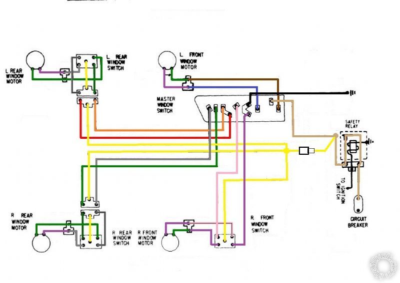
Hi folks, first post here so I hope I'm not creating headaches already! I have a 69 Charger that came with manual windows. From a donor car I got all the power window goodies: wiring, regulators, motors, and switches (4 gang on driver's door). The only thing I don't have is the circuit breaker and the safety relay but I'm not sure if I need them. I have 2 530T modules and the Avital 5303. When this is all hooked up do I still need additional relays? I have already upgraded the car's wiring with a bigger alternator and 6awg wiring. I'm also running an 8 awg wire into the cab with a 50A maxi fuse. All power wires will either go to that fuse or straight to the battery with a new fuse, whichever is recommended. Should I use one module to operate the front windows and one to operate the rears or do one module per side so they're closer to the motors? I am rebuilding the motors so they will run as best as they can, but it's still old technology and don't know what to expect. I'm also hooking everything up outside of the car to make sure it all works. Any tips and advice welcome, please ask whatever info you need. I added a wiring diagram of the stock power windows. I think I know which are the up and down wires but that'll be easy enough to figure out.
Thanks!
D
Replies:
Posted By: howie ll
Date Posted: July 30, 2015 at 8:36 AM
No problem with the windows, just wire to between switch and motors. The safety relay can be left out, if you do your windows will work constantly no need for ignition.
As for the remote start, good luck there with a non-fuel injection car, you might have to install a solenoid on the throttle linkage to prime it.
-------------
Amateurs assume, don't test and have problems; pros test first. I am not a free install service.
Read the installation manual, do a search here or online for your vehicle wiring before posting.
Posted By: dino69
Date Posted: July 30, 2015 at 8:53 AM
Thanks that's great news!
The remote starter was never really a priority and nothing more than a gimmick, it's the alarm and power options that interest me more, but the car does start up amazingly well and has an electric choke. I'll be able to use the remote starter when coming out of the store at least so I can make some heads turn. : )
Posted By: howie ll
Date Posted: July 30, 2015 at 8:56 AM
Yes the lead question is:- can you start just with the key without pumping the throttle in the winter.
-------------
Amateurs assume, don't test and have problems; pros test first. I am not a free install service.
Read the installation manual, do a search here or online for your vehicle wiring before posting.
Posted By: dino69
Date Posted: July 30, 2015 at 9:11 AM
I doubt it. With my old carb I had to push the throttle once and it would fire right up, with the new carb and electric choke I assume I still have to depress the pedal so no the remote starter won't do much good. I can't drive it in the winter here because of snow and ice, but there are plenty cold days where I do take it out. I seriously doubt it would fire up in near freezing temps after sitting 8 hours. EFI is on the menu, but only after I finish grad school which will be in 2018.
Posted By: howie ll
Date Posted: July 30, 2015 at 9:12 AM
OK as long as you're aware of the problem.
-------------
Amateurs assume, don't test and have problems; pros test first. I am not a free install service.
Read the installation manual, do a search here or online for your vehicle wiring before posting.
Posted By: dino69
Date Posted: July 30, 2015 at 8:57 PM
Yep and I'm okay with it.
Would you suggest I run one 530T module per side or one for the front windows and one for the rear or does it not matter?
Posted By: howie ll
Date Posted: July 30, 2015 at 11:30 PM
Doesn't matter!
-------------
Amateurs assume, don't test and have problems; pros test first. I am not a free install service.
Read the installation manual, do a search here or online for your vehicle wiring before posting.
Posted By: dino69
Date Posted: February 18, 2016 at 11:17 AM
Well it took me a while but I'm finally installing these modules!
The car needed a lot more attention so instead of duct taping everything together I pulled the drive train, repaired and repainted the engine bay and I am rebuilding the engine and suspension. The next step on those is painting the components so I need to wait for spring to do so. It's a bit cold right now.
I installed two 530T's; one behind each kick panel. The idea is to use one 530T to operate both windows on each side of the car. It's a 2 door by the way.
I have rebuilt the window motors and the mechanisms, and I have installed new guides and seals everywhere so the windows zip up and down pretty good with the stock switches.
I have yet to install the 5303 alarm and remote starter. I'm also going to install fuel injection but not this year so the remote starter will not be used a whole lot as long as I have a carburetor on there. I do want to wire it in though.
I have a question on wire gauge. I have read somewhere that on these old cars it is recommended to run thicker gauge wiring to the window motors as some people complained that the 530T relays would stop the windows before they rolled all the way up. I know there's a resistor mod but I want to see if I can get this to work smoothly without. I'm using the blue and green wires to interface with the door motor and the blue and green with tracer wires to do the rear quarter window. The former is long enough to run all the way into the door and get to the motors, the others of course don't reach all the way back. The total length from the 530T to the rear window motor is around 6'.
Would it be advisable to cut all four of those wires close to the 530T and solder a thicker gauge wire in place? If so what gauge is recommended? 12? 10?
As for the red fused wires, I guess it's best to run those straight to the battery? I do have a starter relay bolted to the firewall I could run them to. That relay and the battery are connected by a 6 gauge wire and there's another 6 gauge going to the alternator and an 8 gauge wire going into the cab to power up the inside of the car. Come to think of it, I may not have the room to add more wires to that relay.
If I run all the power wires to the battery would it be best to cut the stock wires close to the fuse and solder a thick wire onto it? Those will then go to the battery with another fuse close to the battery itself. If that works, what gauge wire and size fuses should I use?
I will have more questions as I go through this install but for now the wire gauge is what's important so I do this right.
Thanks!
Posted By: dino69
Date Posted: February 18, 2016 at 11:20 AM
I almost forgot; the thinner gauge wires that run from the 530T to the window switches, do those need to be beefed up at all? Again they are long enough to reach the door switch but not the quarter window switch.
Posted By: howie ll
Date Posted: February 18, 2016 at 11:23 AM
The answer is 10 gauge, power and ground directly to the battery. If your newly installed power window motors work smoothly right now everything should be OK.
-------------
Amateurs assume, don't test and have problems; pros test first. I am not a free install service.
Read the installation manual, do a search here or online for your vehicle wiring before posting.
Posted By: dino69
Date Posted: February 18, 2016 at 11:26 AM
Thanks for your very quick reply Howie!
Do you think it would be overkill to beef up the wires going to the motors? So it would be alright to extend them to the quarters with the same gauge wire? I don't mind spending some more to get thicker wires if it helps.
Posted By: dino69
Date Posted: February 18, 2016 at 11:37 AM
Ground to the battery. I'm glad you told me that, I was going to take the violet and black wires and cut them short. There's a frame bolt close to the 530T I was going to run them to.
Posted By: howie ll
Date Posted: February 18, 2016 at 11:40 AM
Don't rely on any frame bolts on an older car unless it's less than 1 ohm between that bolt and the battery NEG.
I remember a colleague doing that on an 81 Golf Gti and wondering why nothing worked!
-------------
Amateurs assume, don't test and have problems; pros test first. I am not a free install service.
Read the installation manual, do a search here or online for your vehicle wiring before posting.
Posted By: dino69
Date Posted: February 18, 2016 at 11:47 AM
Interesting! I'll measure the resistance on a few points, you made me curious now.
I used to have a few ground issues in the past so I changed the stock wiring. I run a bigger negative cable from the battery to the engine block and I also replaced the stock ground strap running from the engine block to the firewall with an 8 gauge wire. That solved several small issues.
I'll make sure the ground wires run to a spot with no resistance, it shouldn't be an issue to run them to the battery if needed. I should have some room left for a few more wires!
I'll stick with the stock gauge wiring to run to the motors and the switches then but I'll get 10 gauge for all the power wires.
Sorry for the previous double post, I only hit the reply button once.
Thanks Howie!
Posted By: dino69
Date Posted: February 24, 2016 at 9:44 AM
Very long post!
Can you guys look this over and see if I have this right?
I am using an Avital 5303 and two 530T units. The functions I would like are pretty basic: arm/disarm with progressive door unlock, trunk unlock by remote and momentary switch under the dash, regular arm/disarm and remote starter operation.
On my car, a 1969 Dodge Charger, the climate control system is vacuum operated so I won't need to use any of the climate/defogger connections. I can just leave certain buttons depressed so when the car starts it's all up and running.
Besides having the windows roll up when arming the system, I may want a separate button to roll them up without arming the system. The alarm's H1/12 connects to either the 530T's H2/3 or H2/4 I think. DO I use the other for this function?
There are a few more Aux options I see but I wouldn't know what to use them for so I'm leaving them unused unless someone has any good ideas for them. I'm open to suggestions!
I have read the manuals front to back and looked all over this forum, but my car is not exactly typical so I still have a bunch of questions, some you can see in the wire description itself such as what to do with certain wires. I just want to make sure I have all this mapped out before I begin:
1. If I'm not using a certain wire, can I just tape it off?
2. Do I use the same fuse amps on the power wires close to the battery as those on the wire itself? For example H1/2 has a 15A fuse to protect the module, do I add a 15A fuse on the 10 gauge wire that goes from that wire to the battery or do I need a bigger fuse?
3. My dome light comes on when I open the door and goes off when I shut it. Is there a way to have the dome light go on when I disarm the car and shut off after I start it? Like a modern car?
4. Regarding IGN 1 and IGN2, I have a modern ignition system which required the coil to see 12v in both run and start positions so IGN1 and 2 have been soldered together. I'm assuming I no longer have to connect the wires for IGN2?
5. Without having to find a dealer, can I turn off the chirps when I arm/disarm the system? If I can, will all the other chirps be disabled as well? That may not be a good idea, what's your opinion on this.
➤ Primary harness (H1), 12-pin connector
H1/1 RED / WHITE (-) 200mA TRUNK RELEASE OUTPUT : to relay, momentary switch to same input as H1/1?
H1/2 RED (+) CONSTANT POWER INPUT : to + battery, fuse amp?
H1/3 BROWN (+) SIREN OUTPUT : to siren red wire
H1/4 EMPTY NOT USED
H1/5 BLACK (-) CHASSIS GROUND INPUT : chassis or negative battery terminal
H1/6 VIOLET (+) DOOR TRIGGER INPUT, ZONE 3
: unused? Door switch is ground when door open.
H1/7 BLUE (-) MULTIPLEXED INPUT, ZONE 4 : unused? No optional sensor only the one that came with the Avital.
H1/8 GREEN (-) DOOR TRIGGER INPUT, ZONE 3
: negative wire w/door open
H1/9 BLACK/ WHITE (-) 200mA DOMELIGHT SUPERVISION OUTPUT
: unused? no dome light supervision.
H1/10 WHITE/ BLUE (-) REMOTE START ACTIVATION INPUT : where does this wire go?
H1/11 WHITE (+)/(-) SELECTABLE LIGHT FLASH OUTPUT
: + parking lights wire
H1/12 ORANGE (-) 500mA ARMED OUTPUT : 530T H2/3 RED / white or H2/4 orange?
➤ Auxiliary harness (H2), 6-pin connector
H2/1 LIGHT BLUE (-) SECOND UNLOCK OUTPUT
: relay, passenger unlock actuator
H2/2 WHITE/ BLACK (-) AUX 2 OUTPUT
: unused?
H2/3 VIOLET/BLACK (-) AUX 1 OUTPUT
: unused?
H2/4 GREEN / WHITE (-) FACTORY ALARM REARM
: unused? No factory alarm
H2/5 GRAY/BLACK (-) WAIT-TO-START INPUT
: unused? No diesel
H2/6 LIGHT GREEN/ BLACK (-) FACTORY ALARM DISARM
: unused? no factory alarm
➤ Door lock harness, 3-pin connector
1 LIGHT BLUE (-) UNLOCK OUTPUT (+) LOCK
: relay, driver unlock actuator
2 EMPTY NOT USED
3 GREEN (-) LOCK (+) UNLOCK OUTPUT
: relay, both doors lock actuators
➤ Heavy gauge relay satellite wiring diagram
H/1 PURPLE STARTER OUTPUT TO STARTER (STARTER SIDE)
: starter wire going to starter
H/2 GREEN STARTER INPUT FROM IGNITION (KEY SIDE)
: starter wire going to ignition
H/3 RED (+) HIGH CURRENT 12V INPUT : to + battery, fuse amp?
H/4 ORANGE OUTPUT TO ACCESSORY CIRCUIT : vacuum operated climate so unused
H/5 PINK OUTPUT TO PRIMARY IGNITION CIRCUIT : ignition wire
H/6 RED (+) (30A) HIGH CURRENT 12V INPUT : unused?
H/7 PINK/WHITE OUTPUT TO SECOND IGNITION CIRCUIT : unused?
H/8 RED / WHITE (+) (30A) HIGH CURRENT 12V INPUT : unused?
➤ Remote start harness, (H3) 5-pin connector
H3/1 BLACK/ WHITE (-) NEUTRAL SAFETY SWITCH INPUT : to toggle switch, other switch wire grounded
H3/2 VIOLET/WHITE TACHOMETER INPUT WIRE : - side of coil
H3/3 BROWN (+) BRAKE SHUTDOWN INPUT WIRE
: brake switch + when depressed
H3/4 GRAY (-) HOOD PINSWITCH INPUT, ZONE 1
: hood pin switch
H3/5 BLUE/WHITE (-) 200 mA 2ND STATUS/REAR DEFOGGER - Latched Pulsed
: unused
➤ Horn, channel 6 (H4), 2-pin connector
H4/1 ORANGE / BLACK (-) AUX 3 OUTPUT
: where does this wire go?
H4/2 BROWN (-) 200 mA HORN
: to horn relay through SPDT relay?
Thanks for looking?
Posted By: dino69
Date Posted: March 06, 2016 at 12:58 PM
Alright then let's try something else. 
I figured out the questions on fuses and such and where all the wires go. But I have a few more questions before I can install everything.
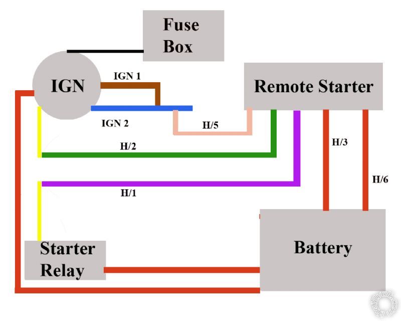
I drew up this crude schematic to show how I believe the RS is connected to this old ignition system.
The car used to have ignition 1 and 2 but due to installing a modern ignition system those wires have been connected. I still have one power wire coming in from the fuse box and one from the battery fused . As I understand, either ignition 1 or 2 would have power only in crank and the other would have power only in run. Since they are tied together it probably doesn't matter anymore and I should ignore the RS ignition 2 wires. I also don't have an accessory wire going to climate control or anything like that so that leaves only 5 wires to connect. Two 3oA fused power wires that go to the battery (H/3 & H/6), a pink wire going to the joined IGN1 and IGN2 wires (H/5). Lastly the green (H/2) and purple (H/1) wires that g to the cut wire that runs from ignition switch to starter relay.
Did I get it right?
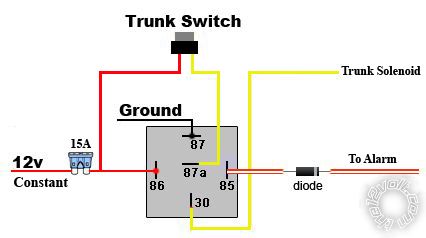
I also found a few diagrams on how to wire the trunk popper relay and adapted it to this. I think this is how it's supposed to be. Would there be any point in wiring the power for the dash switch to key on power only instead of constant power? I can't think of any but thought I'd ask.
I'm not sure what to do with the dome light. If anything I'd like it to light up when I unlock the car and turn off when I start it, but I don't know if it's possible. I may just leave it alone if it's too much trouble.
I decided not to use the siren that came with the Avital 5303. I don't like it and I really don't care for the chirps. I just want the parking lights to flash when I arm/disarm.
I do want the horn to pulse when the alarm is triggered so can I simply leave the siren unhooked and use the H4/2 horn output? It's a 200mA feed and my horns are already tied to a horn relay (stock). If I add this wire to it will it give me a pulsed output? There's no explanation in the manual about what this does. There's also H4/1 but that's an Aux 3 output and I don't know what it's for.
Posted By: Custom_Jim
Date Posted: March 07, 2016 at 4:06 PM
While I cannot answer all of your questions I can give some insight on the trunk solenoid wiring and the horn.
I'm guessing that the trunk switch you show and the trunk solenoid are already in the car and that the trunk switch throws or sends 12 volts to the solenoid to get it to activate. If so, leave that how it is but somewhere on the wire between the trunk switch and the trunk solenoid, you need to splice into that wire and then connect terminal 87 of an aftermarket relay to it. On that same relay you then need to connect terminal 30 and 86 to a fused constant 12 volts and then terminal 85 to the negative trunk output from the alarm or remote start control module/brain. Terminal 87A will not be used at all.
IF your existing trunk switch is hooked to a fused constant or ignition 12 volts then you could take and connect terminal 30 and 86 of the relay to it BUT if the existing trunk switch is getting power from an ignition source, then the remote control for the alarm or remote start can only activate the relay when the ignition is on and not when the ignition is not powered up. Some alarms and/or remote starts I've seen do not allow the trunk output to work when the key is in the run position so it might be better to get a fused constant 12 volts for terminals 30 and 85.
As far as your other questions I would think you could use the existing horn relay on the car and tie it into the new system providing the polarity is correct and the factory relay draws the same or less than what that output can handle. The only way to know would be to measure what you have. I'm a GM guy but on my 68 Chevy II, the horn relay is triggered by a negative connection in the horn button BUT just looking at the size of my original relay I might think that it could draw more than what an alarm output could handle and instead of taking a chance I would measure things and if it's fine, then I could get by without an added relay. I would just hate to say do it and then find out your factory horn relay draws too much power to where it fries things.
Jim
-------------
1968 Chevy II Nova Garage Find 2012
1973 Nova Custom
1974 Spirit of America Nova
1973 Nova Pro-Street
Posted By: dino69
Date Posted: March 07, 2016 at 7:51 PM
Thanks for the advise Jim!
Very good point on the horn relay. It is pretty big so it may be too much for the alarm output. I'll try to figure out how to wire in an spdt relay. The horn on my car is triggered by a negative connection as well.
The trunk solenoid and switch came out of another car. Chargers didn't come with them. It's a single wire solenoid so putting power to it makes it go. I will be sure to give the switch constant power so it'll work with the remote when the ignition is off.
I'll draw up a new relay schematic for it tomorrow and post it to make sure I did it right.
Posted By: Custom_Jim
Date Posted: March 08, 2016 at 11:45 AM
dino69 wrote:
With my old carb I had to push the throttle once and it would fire right up, with the new carb and electric choke I assume I still have to depress the pedal so no the remote starter won't do much good. I can't drive it in the winter here because of snow and ice, but there are plenty cold days where I do take it out. I seriously doubt it would fire up in near freezing temps after sitting 8 hours. EFI is on the menu, but only after I finish grad school which will be in 2018.
It seems to me I've read or saw pictures of someone using something like a door lock actuator on the carb linkage to blip the throttle open to set the choke and also put the choke cam on a high idle and then once the car warms up but is still on the high idle and being controlled by the remote start system a secondary signal is sent to the actuator to blip the throttle again to take it off of the high idle cam.
Yes, it would require some work and engineering but I've seen harder things done on older cars with good results.
As far as the existing horn relay, put a meter inline on the horn activation wire and take a reading. If it draws let's say 100mA or less and the remote system can control up to 200mA, then it should work fine but if the factory relay is just a tad under this 200mA, then I would run an additional relay.
Jim ------------- 1968 Chevy II Nova Garage Find 2012
1973 Nova Custom
1974 Spirit of America Nova
1973 Nova Pro-Street
Posted By: dino69
Date Posted: March 10, 2016 at 10:27 AM
I've read sthis as well where someone used actuators to remotely operate the choke. Quite nifty!
I thought about doing it but the car will see very little road time in the next two years and once school is over with I will install EFI.
I'm going to measure the horn relay in a little while and see what I get.
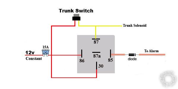
I drew up a new trunk relay schematic according to your recommendations. I'm assuming there is no need for a ground on the relay itself because the solenoid is grounded?
With this setup I then should have the ability to open the trunk by dash switch or remote when the ignition is off correct?
Just out of curiosity, why would it not have worked according to the first schematic I posted?
Posted By: Custom_Jim
Date Posted: March 12, 2016 at 4:38 PM
On your first trunk release diagram, you have the trunk solenoid on terminal 30. That's fine. With that relay is just sitting there, terminal 87A is connected to terminal 30 to where if you push the original factory trunk switch you will send 12V to terminal 87a which then is already connected to 30 which then allows 12 volts to get to the trunk solenoid and it clicks and opens the trunk. This is still fine.
On that same relay wiring you then show terminal 86 being connected to 12v and when the alarm creates a ground through the diode on terminal 85, the relay clicks but then terminal 30 is then connected to terminal 87 which you shows goes to a ground. The trunk solenoid then see's a ground but reality it needs 12v instead.
In your first relay diagram instead of running terminal 87 to ground, you could have run this to terminal 87A which would then send 12v out to terminal 30 but to me your second diagram is how I think most do it.
Most of the time when I was working on the trunk release wiring, I would get most of the connections at the switch as long as the power side was a constant 12 volts. I then only had to run the trigger wire for the new relay to the alarms negative trunk output wire or terminal.
Sometimes with the second wiring you show allows a person to run a slightly cheaper relay as it would not have the 87A portion. Most of the time today, the 5 terminal relays are abundant and used most of the time.
Jim
-------------
1968 Chevy II Nova Garage Find 2012
1973 Nova Custom
1974 Spirit of America Nova
1973 Nova Pro-Street
Posted By: dino69
Date Posted: September 09, 2018 at 9:31 PM
Well it's been over two years, school is done and I'm a Certified Physician Assistant! The car did not get a whole lot of attention during that time and in fact I picked up where I left of today.
I will have to reread just about everything about the 5303 as I have forgotten much of it. The window units are installed and just need to be grounded and hooked up to the 5303.
EFI is going onto the Charger so I'l be able to use the remote start. It's good to be done with school and it's good to be back!
Posted By: dino69
Date Posted: October 27, 2018 at 8:36 PM
Slow going as I needed to do a whole bunch of other things to this car but I'm getting there. I have one issue I can't quite solve though...
I initially planned on using this wire to operate the relay feeding the trunk solenoid, because it kinda says so! :-) H1/1 RED/WHITE (-) 200mA TRUNK RELEASE OUTPUT
The trunk would then be opened by pressing the AUX button on the remote. Great!
However, I was looking at the instructions for the 530T modules that operate the windows and it looks like the AUX button is the one that needs to be pressed 1.5 secs to vent and 3 secs to fully open. If I use another channel to operate the windows then it would have to be pressed 4.5 secs. So I really want this to be no more than 3 secs so the H1/1 red/white wire should be connected to the 530T H2/3 red/white wire and NOT to the trunk relay.
That's all fine and dandy but now how do I operate the trunk solenoid? The Avital 5303 manual says there are a few combinations of buttons to operate something, like a trunk solenoid, but I don't know which combo applies to which AUX channel. Anyone know?
Also is there any other way to operate the trunk instead of holding two buttons at the same time? I'd rather be able to do this with one hand but the only two buttons I can comfortably press together one handed are lock and unlock. This operates the timer mode though and I guess I can't pick and choose what those buttons do.
Any help is greatly appreciated.
Posted By: geepherder
Date Posted: October 27, 2018 at 11:24 PM
Assuming the 5305L (Avital) manual is the same as the 5305V (Viper) manual in the downloads section, you can use either AUX 4, 5 or 6.
AUX 4 would be the violet/black wire (pin 19) in the 24-pin harness controlled by the arm and aux buttons pressed simultaneously.
AUX 5 would be the white/black wire (pin 5) in the 24-pin harness controlled by the disarm and aux buttons pressed simultaneously.
AUX 6 would be the orange/black wire (pin 8) in the 24-pin harness controlled by the disarm and star buttons pressed simultaneously.
-------------
My ex once told me I have a perfect face for radio.
Posted By: dino69
Date Posted: October 28, 2018 at 8:55 AM
Thanks!
I went over the Avital install manual again and these are the AUX channels I find:
H2/2 white/black AUX 2
H2/3 violet/black AUX 1
Both are in the 6 pin connector harness
H4/1 orange/black AUX 3
This one's in the 2 pin harness
So pretty darn similar but no indication in this manual or the owner's manual which operates which buttons. Assuming the colors match what you wrote then maybe the operation is the same. Only one way to find out I suppose!
Thanks for the help!
Posted By: geepherder
Date Posted: October 28, 2018 at 2:12 PM
This is for a 5303, but it sounds similar to what you're describing:
https://www.directeddealers.com/manuals/IG/Avital/N5303_2008_07web_.pdf
Check page 37 for standard configuration.
-------------
My ex once told me I have a perfect face for radio.
Posted By: dino69
Date Posted: October 28, 2018 at 7:25 PM
I actually have the 5303, I didn't notice you said 5305 in your previous post.
So color me blind! I went through that manual so many times and I never saw that page. My bad my bad!
Alright, looks like I now have to pick the best combo to operate the trunk and I'm all set.
Thanks again!
Posted By: geepherder
Date Posted: October 29, 2018 at 7:41 AM
Ha!
After re-reading the title of this thread, I'm not sure where I got 5305 from.
-------------
My ex once told me I have a perfect face for radio.
Posted By: dino69
Date Posted: October 29, 2018 at 10:32 AM
No worries! I'm glad you replied and got it figured out for me!
Question on the diode I need to use between the trunk relay and alarm wire.
Would any of these work or do I need another type?
Posted By: geepherder
Date Posted: October 29, 2018 at 2:23 PM
Those are resistors, not diodes.
If you have one of the few RadioShacks left near you, they used to have a 25 pack of generic 1 amp switching diodes. Microcenter or Fry's should have diodes as well.
-------------
My ex once told me I have a perfect face for radio.
Posted By: dino69
Date Posted: October 29, 2018 at 4:40 PM
Oh oops :oops:
Radio Shack here is long gone, but I'll find one somewhere.
Tried soldering two 10 awg wires today and no go with my pencil iron. How much watt should it be?
Posted By: geepherder
Date Posted: October 29, 2018 at 6:14 PM
1 amp diodes will be fine.
Soldering big wires like that is easier with a small butane torch.
-------------
My ex once told me I have a perfect face for radio.
Posted By: dino69
Date Posted: October 29, 2018 at 6:17 PM
Alright I'll pick up a butane torch tomorrow. I have a few of these big wires to do.
Thanks again for all the help, I really appreciate it.
Posted By: dino69
Date Posted: October 30, 2018 at 9:32 PM
I bought a mini torch which made short work of these fat wires. I also bought 1n/4001 diodes so I can finish this project.
Posted By: dino69
Date Posted: November 06, 2018 at 2:56 PM
I finished all the wiring but not everything works. The door locks do not work, which is odd seeing it's just two wires, and I have no power going to my windows at all. I do hear both 530T's clicking so they're getting power. I'll have to go over the original window wiring loom, I must have missed something.
The door locks have me puzzled though.
I cannot test the remote starter yet as there is no ignition or fuel system installed yet but I'm optimistic it will work.
When I arm and disarm the alarm system I do get one chirp for arm and two chirps for disarm so that seems to work. The remote also buzzes accordingly. Trunk lock also works fine.
The shock sensor LED lights up when I bump the car, this is with the alarm disarmed. I wasn't up for a full blown siren in my closed garage just yet!
Any clue as to what may have happened with the door locks? The actuators work fine when touching the wires to the battery but once hooked up to the brain it's a no go.
Posted By: dino69
Date Posted: November 06, 2018 at 3:33 PM
Correction, when arming the alarm it chirps once. I forgot to push down the hood switch (hood is no on the car) so it gave me a second bypass notification chirp.
Posted By: geepherder
Date Posted: November 06, 2018 at 8:33 PM
It's hard to tell without knowing how they are connected. In the relay section, look at diagram 12. I'd post the link, but my phone is misbehaving.
Are your locks connected like that?
-------------
My ex once told me I have a perfect face for radio.
Posted By: dino69
Date Posted: November 06, 2018 at 8:40 PM
That's the diagram I used yes but I must have done something wrong. Thanks for confirming that at least I used the right diagram! I will be working on the car again on Thursday so I will update my findings. I ust realized I didn't use any diodes there, should there no be one?
Posted By: geepherder
Date Posted: November 06, 2018 at 10:56 PM
While it will probably work fine without diodes, many installers recommend placing them across the relay coil. I've done it both ways. If you choose to use them, just make sure you connect the striped side (cathode) to the side with positive voltage connected. If you try to connect them the other way they will explode when powered.
Verify your power and ground connections, then check fuses. If you have no issues there, verify the power lock/unlock outputs on the alarm.
-------------
My ex once told me I have a perfect face for radio.
Posted By: dino69
Date Posted: November 09, 2018 at 9:50 AM
My bad, I wired one of the relays wrong. Doors are now fully functional!
No power to the windows yet so I have to trace a few wires but I'll find it.
Posted By: dino69
Date Posted: November 11, 2018 at 7:19 PM
I have power to the windows but the 530T modules are not working for some reason. I can operate all 4 windows with the master switch, and I can operate both passenger windows with their individual switches. The driver side rear window switch is not working though. I tried another and still no go so not sure what's going on.
When I hold the Aux button on the remote for a few seconds I can hear both 530T modules click, but that's all they're doing. Fuses are good. Where do I start looking?
Posted By: dino69
Date Posted: February 05, 2019 at 8:18 PM
If anyone is still reading this, I found the issue and everything is working as it should. It's pretty cool to have all these upgrades in an old Charger.
|