2005 Dodge Ram W/ CommandStart CS-380i
Printed From: the12volt.com
Forum Name: Car Security and Convenience
Forum Discription: Car Alarms, Keyless Entries, Remote Starters, Immobilizer Bypasses, Sensors, Door Locks, Window Modules, Heated Mirrors, Heated Seats, etc.
URL: https://www.the12volt.com/installbay/forum_posts.asp?tid=139434
Printed Date: April 05, 2026 at 3:59 PM
Topic: 2005 Dodge Ram W/ CommandStart CS-380i
Posted By: rayf01
Subject: 2005 Dodge Ram W/ CommandStart CS-380i
Date Posted: September 16, 2015 at 1:50 AM
I have a 2005 Dodge Ram W/ CommandStart CS-380i installed in it. When I bought it used back in 2008, I notice the key fob for the started the truck, but the lock button's didn't work so I have to carry both fobs.
I finally got annoying today and wanted to figure out what was up. I took the dash apart and saw that the 2-Brown (lock) and 3-green (unlock) wires off coming from the 12 pin wiring harness from the module are not connected to anything. When I hit the button on the started I hear clicking like a relay, I am assuming inside the module itself, but obviousl nothing happens.
Can I connect these two wires to wires on the truck to have the door locks work?
A link to the install manual is here:
https://dealers.automobilitydistribution.com/webapp/e-cellsell/e-commerce/webb2b/IC5/Techsupport_install_guides/COMMANDSTART/CS-380i-HF/CS-380i%20HF%20install%20english.pdf
Any help would be appreciated.
Replies:
Posted By: rayf01
Date Posted: September 16, 2015 at 1:56 AM
Also I guess I should say, as per that manual I posted. Each of the outputs for those wires is a 500ma Negative output I think:
2 BROWN () Lock output Programmable 500 mA negative output: 7/10-sec. or 4-sec. pulse.
3 GREEN () Unlock output Programmable 500 mA negative output: 7/10-sec., 4- sec. or double 1/4-sec. pulse
None of the other wires on the 12 pin connector are connected other than the white ground out while running. Not sure if I need the arm or disarm as well.
Posted By: rayf01
Date Posted: September 16, 2015 at 2:34 AM
From the research I am seeing I need two resistors I think?
Posted By: kreg357
Date Posted: September 16, 2015 at 6:27 AM
Here is the info from ReadyRemote :
Power Lock PURPLE / dk. green (-) 820 ohms @ driver kick, door harness
Power Unlock same as power lock wire (-) 330 ohms @ driver kick, door harness
Note : Lock is negative trigger thru an 820 ohm resistor. Unlock is negative trigger thru a 330 ohm resistor. MUST use relays.
While it might work with just in-line resistors from the CS-380i, I would buy a DEI 451M door lock module. The cost ~$9 and
comes with the correct value resistors. It's a nice compact module that houses the needed relays and make the job neat and
easy. Here is a link to the 451M install guide : https://www.the12volt.com/installbay/file.asp?ID=726 Follow Diagram H. ------------- Soldering is fun!
Posted By: howie ll
Date Posted: September 16, 2015 at 12:45 PM
Kreg you're right as usual, 500 milliohm wont get past the resistors, use a 451M.
BTW isn't this a double pulse for lock and unlock?
-------------
Amateurs assume, don't test and have problems; pros test first. I am not a free install service.
Read the installation manual, do a search here or online for your vehicle wiring before posting.
Posted By: rayf01
Date Posted: September 16, 2015 at 5:33 PM
SO yeah, I just hooked up the resistors only, and I managed to have the lock work, but unlock doesnt. Then as soon as the truck is running, neither work. So I guess I buy one of those 451M units? I'll just order it off amazon.
Thanks.
Posted By: rayf01
Date Posted: October 12, 2015 at 8:18 PM
Hoping I can get some help here. Not sure if I am doing something wrong.
I received my 451M module. It has 5 big wires, and then three small wires that are apparantly for DEI systems that I don't think I use (they have a little 3 pin connector on them).
Now, the 5 big wires, I believe the WHITE/ Black and BROWN / Black are not use, so I taped them up.
That leaves me with the following, and how I connected them:
Wires coming off the relay:
1. GREEN/ Black - Connected to 820 Ohm Resistor.
2. Blue/Black - Connected to 330 Ohm Resistor.
- I Then connected both of the resistor ends together and then tied them to the PURPLE / black wire under my dash which I think is the lock common wire for my door locks.
3. Violet&Violet/Blck - They were terminated already together in to a fuse. then a single violet comes out. I connected this to the GREEN/ Brown wires coming off my car starter which in the manual says those wires are the unlock/lock negative contacts. I connected it this way because it says input which I assume is input from the car starter?
My only concern is that the violet inputs on the relay say they should be connected to a 15amp ground? Im really confused as if I do that there is no input in to the actual relay then from the car starter...

Also is there a way to test the relay to see if its working? I accidentally connected the three pin connected in to the 556u immobilizer bypass by mistake. When there was a different three pin connect that was supposed to go in to that 556U.
Posted By: kreg357
Date Posted: October 12, 2015 at 9:11 PM
Not doing too good with the 451M.
First, the 3 Pin connector, cut the end off it and connect the Green wire to the CS380i's (-) Lock output. Connect the Blue wire to the
CS380i's (-) Unlock output. The Red wire goes to a +12V constant source. You can add a 2 Amp fuse if you wish.
Next for the thick wires we follow the Type H diagram.
You have the GREEN/ Black with the 820 ohm resistor OK and the Blue/Black with the 330 ohm resistor OK. These two wires should go
to this wire : PURPLE / Dark Green @ driver kick, door harness
The fused Violet wire should go to any solid Chassis Ground. The other two wires are not used, just cut and insulate them. ------------- Soldering is fun!
Posted By: rayf01
Date Posted: October 12, 2015 at 10:39 PM
Well I was definitely a little off hey? I'll give it a go. Thank You.
Posted By: kreg357
Date Posted: October 14, 2015 at 5:12 AM
Sorry, didn't mean to sound harsh. The 451M is a small neat package that comes with a wide variety or resistors that replaces this :
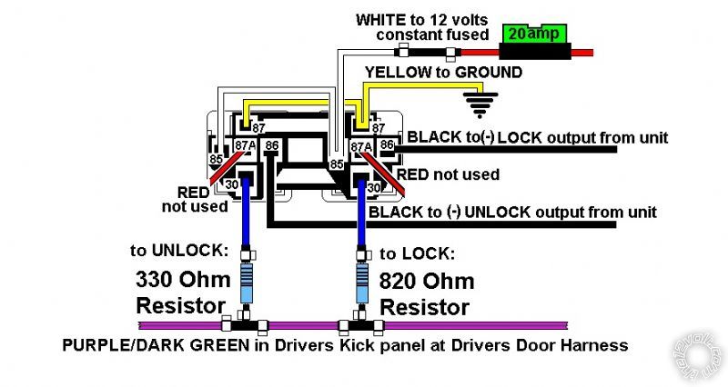
Basically it's just two relays, like the above Bulldog Security diagram, with the following wire color differences.
The Black Lock is the same as the 451M's Green.
The Black Unlock is the same as the 451M's Blue.
The White is the same as the 451M's Red. ( A 2 Amp fuse is all you need.)
The Blue Lock is the same as the 451M's GREEN/ Black.
The Blue Unlock is the same as the 451M's Blue/Black.
The Yellow Ground is the same as the 451M's Fused Purple.
Finding the correct PURPLE / Dark Green wire in the Driver Kick Panel might be the most difficult part of the wiring. It will be in the harness
that goes out into the driver's door. ------------- Soldering is fun!
|