Viper 5906v on a 2000 Cadillac Deville
Printed From: the12volt.com
Forum Name: Car Security and Convenience
Forum Discription: Car Alarms, Keyless Entries, Remote Starters, Immobilizer Bypasses, Sensors, Door Locks, Window Modules, Heated Mirrors, Heated Seats, etc.
URL: https://www.the12volt.com/installbay/forum_posts.asp?tid=139871
Printed Date: May 06, 2026 at 1:38 PM
Topic: Viper 5906v on a 2000 Cadillac Deville
Posted By: ttimms20
Subject: Viper 5906v on a 2000 Cadillac Deville
Date Posted: December 08, 2015 at 11:44 AM
I'm a 1st time installer and I'm installing a Viper 5906 on my 2000 Deville. For the most part I understand by I'm not sure what bypass module I need, i.e. xk01, xk09, dball2 and how to flash it to my vehicle. I'm also adding a motion sensor and not sure where and how it plugs in. Any suggestions will help thanks.
-------------
We Ride
Replies:
Posted By: dairyboy3
Date Posted: December 09, 2015 at 1:14 PM
I would use the dball2. But you can use an xk09 but the dball is newer. Either way you will need a DEI account to flash the module on the computer. If you don't have one you will have to find a shop or someone who does.
Posted By: ttimms20
Date Posted: December 21, 2015 at 11:55 PM
On the viper 5904, the RED, RED / WHITE, RED / BLACK on the Ignition harness hooks up to what on the vehicle...
-------------
We Ride
Posted By: ttimms20
Date Posted: January 10, 2016 at 3:23 AM
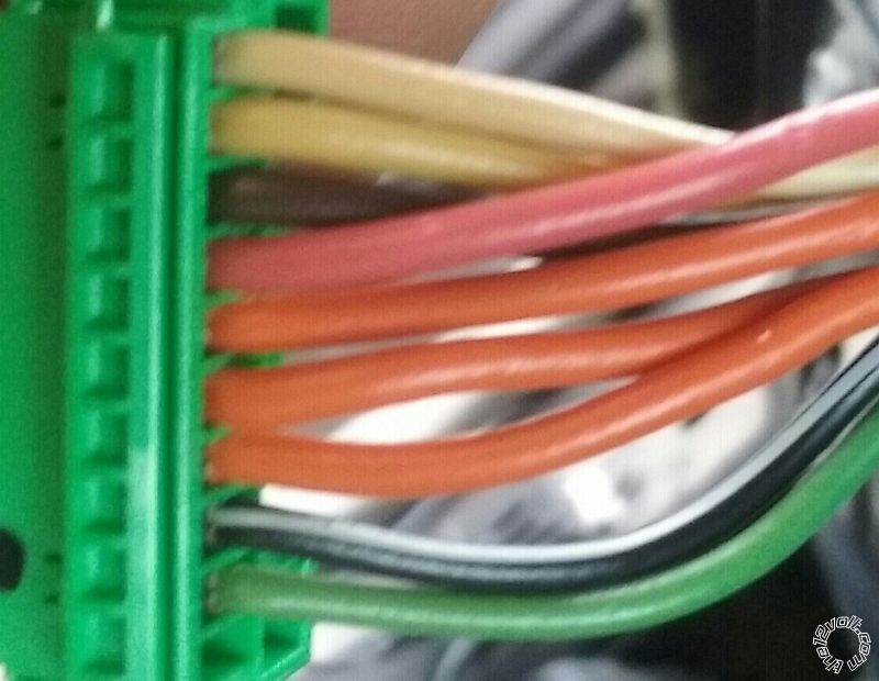
Do i need a relay on my trunk release and any of my ignition wires on this car. Ignition wires are small gauge. I also have 3 orange wires coming out of my ignition harness as well, anyone with a more detailed diagram of what the wires are.
-------------
We Ride
Posted By: ttimms20
Date Posted: January 10, 2016 at 3:26 AM
 ------------- We Ride
Posted By: ttimms20
Date Posted: January 10, 2016 at 1:07 PM
Ok tested all wires and I'm getting:
White- on in acc, on/run, start/crank
Yellow- on in start/crank
Brown- on in acc, on/run
Pink- on in on/run, start crank
Orange1- on in all positions
Orange2- on in on/run
Orange3- on in all potions
BLACK/ white- nothing
Green- nothing
So off all this I know my
Orange1 and Orange3- Bat1 and Bat2
Yellow- start
Pink- Ignition 1
Brown- acc 2
The Orange2 is saying it's the Acc on the tech sheet bit acting more like the Ign2
The White wire is saying it's Ign2 on the tech sheet but acting more like a Acc wire.
-------------
We Ride
Posted By: mscguy
Date Posted: January 10, 2016 at 6:01 PM
https://www.readyremote.com/main.asp?action=select&yr=2960&product=Remote%20Start&make=Cadillac&model=DeVille#
Posted By: mscguy
Date Posted: January 10, 2016 at 6:08 PM
I would suggest going to the battery for your +12vdc connections.
Those 2 orange wires you tested that are on in all Positions, share a common 15amp fuse that powers numerous things.
Posted By: ttimms20
Date Posted: January 10, 2016 at 7:09 PM
That site did it all thanks, make it much more smoother. Thanks major help.
The 5906v comes with a defogger aux wire, will I need a relay to make that function d/t it being latched. If so what amp relay...
The 508d pro sensor calls for a Warnaway wire, am I correct in jumping this from the green shock sensor wire.
-------------
We Ride
Posted By: ttimms20
Date Posted: January 13, 2016 at 3:03 AM
I don't care about having or using the factory alarm so do I really need to hook up the oem factory arm and oem factory disarm wire from the viper alarm. Will it affect anything by not hooking them up.
-------------
We Ride
Posted By: mscguy
Date Posted: January 13, 2016 at 9:57 PM
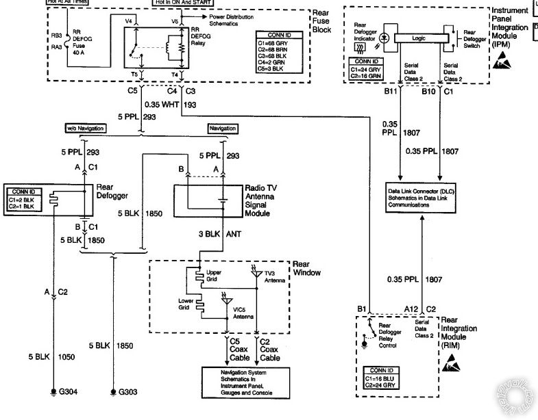
The connection for your defogger wire Is in the rear fuse box.
Its (-)White. Connector C3? Make sure to test. I don't know if you can pick it up at the front anywhere.
I don't know about your alarm question. If you press the lock button with the door open, than close the door, I believe it will arm it. So, unless the factory alarm shuts off when the remote start activates, when you open the door, or even use the unlock button on your viper, it may set it off. I guess it you never lock the door with it open, you would be ok.
If you can get to it, you may as well connect it.
Posted By: ttimms20
Date Posted: January 17, 2016 at 8:32 PM
I found the white wire at the fuse box and it shows +12v when the defroster is off and no power when it's on. Any idea how to wire it up.
-------------
We Ride
Posted By: mscguy
Date Posted: January 17, 2016 at 8:37 PM
So, using your dmm, red probe on the white wire and the black probe on ground, shows +12 when defrost is off and 0 when its on? That means it's a switched ground.
You should be able to connect whatever wire you want to use (2nd status,aux whatever,) directly to it.
It's small, like 20gauge right?
Posted By: ttimms20
Date Posted: January 17, 2016 at 8:58 PM
So just tap right in with a -200mA is what your saying, and no relay
-------------
We Ride
Posted By: mscguy
Date Posted: January 17, 2016 at 9:14 PM
Looks that way to me. Circuit 193
Posted By: ttimms20
Date Posted: January 17, 2016 at 9:50 PM
Whoa you thru me, I'm lost
-------------
We Ride
Posted By: mscguy
Date Posted: January 17, 2016 at 9:55 PM
Sorry. Just showing you what's going on.
Yes. Just connect the -200ma wire directly.
If you're using the 2nd status/Defog wire, make sure to change the programming, otherwise your Defog will be on every time you remote start.
Posted By: ttimms20
Date Posted: January 17, 2016 at 10:26 PM
Cool now a issue question my accessories in the the car during remote start was working at first now there is no power during remote start on that wire from the brain. Any ideas......
-------------
We Ride
Posted By: mscguy
Date Posted: January 17, 2016 at 10:44 PM
Which wire?
You have two ignitions and two accessories. How did you connect them?
Where are all your fused Red wires connected to?
Posted By: ttimms20
Date Posted: January 17, 2016 at 11:55 PM
Orange accessory 1
Brown accessory 2
-------------
We Ride
Posted By: ttimms20
Date Posted: January 18, 2016 at 1:52 AM
85 & 87 30amp fused constant
-------------
We Ride
Posted By: mscguy
Date Posted: January 18, 2016 at 6:54 AM
Can you elaborate on that?
Where are you drawing your +12v from for all your red fused wires? Did you go to the battery or are you trying to use the two orange wires at the ign switch?
Your viper has a flex output. Are you using it for the 2nd ignition or 2nd acc, and did you change the programming to reflect that.
How did you wire a relay for the other 2nd wire?
Does everything still work normally when starting with your key?
Posted By: ttimms20
Date Posted: January 18, 2016 at 10:43 AM
I ran a 4 ga wire from under the seat to a distribution block under the dash. Fused RED / black - RED / white - red in it.
Ign1 in/out pink - pink ign harness
Ign2 pink/white - white ign harness
Starter green - yellow keyside
Starter violet - yellow carside
Accessory output orange - orange ign harness
24 pin harness:
Accessory output orange - brown ign harness on relay..
87&86-12v constant (was a 30 amp fuse and changed to 20) resistor jump also
85-orange accessory wire off 24 pin harness
30-brown ign harness wire
-------------
We Ride
Posted By: ttimms20
Date Posted: January 18, 2016 at 10:45 AM
Flex relay function ign2
-------------
We Ride
Posted By: mscguy
Date Posted: January 18, 2016 at 12:48 PM
So, you have no reading on the viper orange acc wire during remote start.
Is there a reading on pink/white?
Does everything work with the key?
I assume you checked all your fuses with a meter?
What is that resistor you mention?
Posted By: ttimms20
Date Posted: January 18, 2016 at 1:11 PM
No reading on the orange dururemote start
Pink/white hot during remote start
Everything works fine with the key on
Fuses checked
Resistor came built in relay harness in 85&86 slot
-------------
We Ride
Posted By: mscguy
Date Posted: January 18, 2016 at 3:04 PM
It's probably a diode, not a resistor on that relay.
Odd. The wiring looks ok. is your connector seated all the way? Any bent pins? That connector is pretty beefy but you never know.
You have 3 orange wires in your ign switch. Did you connect to the right one?
Posted By: ttimms20
Date Posted: January 18, 2016 at 3:17 PM
Yes sir, it was working at first.
-------------
We Ride
Posted By: mscguy
Date Posted: January 18, 2016 at 3:21 PM
Are you still getting +12v on the RED / black at the connector?
Posted By: mscguy
Date Posted: January 18, 2016 at 3:22 PM
Where is your ground wire going?
Posted By: ttimms20
Date Posted: January 18, 2016 at 3:55 PM
Yes they are all hot except the Accessory wires, and I sanded past the paint and grounded
-------------
We Ride
Posted By: ttimms20
Date Posted: January 18, 2016 at 3:56 PM
I'm using the 998t to program the alarm if that helps
-------------
We Ride
Posted By: mscguy
Date Posted: January 18, 2016 at 9:45 PM
That is odd. I honestly don't know why it wouldn't put out anything on your ign wire. I'm not familiar with a bit writer so I can't comment on that.
Posted By: mscguy
Date Posted: January 18, 2016 at 9:47 PM
Did it stop working after you changed a setting in the bitwriter or did it just stop working by itself?
Posted By: mscguy
Date Posted: January 18, 2016 at 9:56 PM
Are you still getting a ground signal from your orange acc wire on the 24 pin plug where you have your pin 85 on your relay connected to?
If so, (it would be more wiring) but you could take that acc relay, and use it to drive 2 other relays to power your two acc wires.
You don't want to hook up two relays to 1 200ma wire.
Posted By: ttimms20
Date Posted: January 18, 2016 at 10:15 PM
How would I wire that up and I connected the blue/white directly to the white defrost wire and I'm still getting a feature not available on the screen
-------------
We Ride
Posted By: mscguy
Date Posted: January 18, 2016 at 10:31 PM
If using the 2nd status as the Defog output, it turns on by itself below a certain temp. I can't remember what temp it is though.
Make sure your 2nd acc relay is stil functioning before worrying about doing more relays. I assume it is, but just making sure.
Posted By: ttimms20
Date Posted: January 18, 2016 at 11:05 PM
How would I test that
-------------
We Ride
Posted By: mscguy
Date Posted: January 18, 2016 at 11:10 PM
Measure pin 30 of your acc relay you wired. If you're getting 12 volts during remote start, it works.
I wonder if your unit is damaged somehow causing nothing to be output from your orange acc wire.
Posted By: ttimms20
Date Posted: January 18, 2016 at 11:21 PM
No power there either. Here is a picture of what appears to be a resistor on the relay harness 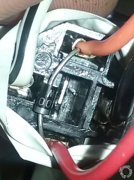 ------------- We Ride
Posted By: mscguy
Date Posted: January 18, 2016 at 11:26 PM
That's a diode. It's good that it's there, as long as the grey band is toward 86. You said 86 was +12vdc.
So, you're getting no voltage to either acc 1 or 2 then at your ign switch during remote start?
Posted By: mscguy
Date Posted: January 18, 2016 at 11:29 PM
Try something else. Put your voltmeter red probe on +12v and black probe on the -200ma accessory wire. It should show 12 volts during remote start.
Posted By: ttimms20
Date Posted: January 18, 2016 at 11:29 PM
None what could burn out the wires but not blow a fuse or affect the remote start also
-------------
We Ride
Posted By: mscguy
Date Posted: January 18, 2016 at 11:34 PM
At any point did you connect any of those small 24 pin wires directly to anything at your ignition switch or the remote start harness?
Posted By: ttimms20
Date Posted: January 18, 2016 at 11:35 PM
Nothing on that also
-------------
We Ride
Posted By: ttimms20
Date Posted: January 18, 2016 at 11:38 PM
I don't recall doing so
-------------
We Ride
Posted By: mscguy
Date Posted: January 18, 2016 at 11:48 PM
Well, unless something got changed in the bitwriter that would disable your accessory output, I would say that your brain is no good. I'm not a pro, but I can't think of anything outside of your starter module that would not allow anything out of your acc wire.
Check your +12 connections to that 4gauge wire again. Make sure they're tight, and check your fuses with a volt meter. One probe on either side of fuse. Should read 0 volt.
Maybe change your ground too. You said it's sanded to metal, but is it to the body or the dashboard? Dashboards don't always have the best electrical connection to the body.
Posted By: ttimms20
Date Posted: January 19, 2016 at 12:12 AM
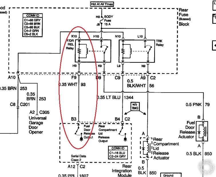
Ok thanks, I'll try to have them swap the unit out. Also on the rear defogger I have a option for it on the remote. So just the temp have to. E low for me to be able to use it. Also do I need a relay for the gas door to be on one of the aux options.
-------------
We Ride
Posted By: mscguy
Date Posted: January 19, 2016 at 12:25 AM
Doesn't look like you need a relay.
Rear fuse block, Connector C2 (brown), Pin F9. White wire. Test to make sure though.
Posted By: ttimms20
Date Posted: January 19, 2016 at 12:45 AM
Wired ot directly to the wire at the fuel do switch, set for validity and it works fine
-------------
We Ride
Posted By: davep.
Date Posted: January 19, 2016 at 5:49 PM
On about page 3 he indicates he used the 24-pin (-200ma) orange accy wire to control a relay for the car's Brown accy wire. The way it's written, it looks like he hooked the 24-pin orange directly to the Brown wire. If he did, that's why there's no ACCY output. The 24-pin orange AND the large gauge orange ACCY output's internal relay control are common. If he applied 12V to the little orange, and fried the junction, the big orange won't work either.
Carry on.
Posted By: kreg357
Date Posted: January 19, 2016 at 6:15 PM
+1 with Davep.
-------------
Soldering is fun!
Posted By: mscguy
Date Posted: January 19, 2016 at 6:22 PM
Yeah that's right, but I read it the other way. I read it as he connected it to the relay as written below in that post.
If he did connect it wrong, that would do it.
Posted By: ttimms20
Date Posted: January 19, 2016 at 10:53 PM
How should it be connected to the relay, I never tried to go directly from the little orange 24 pin to the brown wire. It always went thru the relay but it may be wired wrong.
-------------
We Ride
Posted By: ttimms20
Date Posted: January 19, 2016 at 10:56 PM
Accessory output orange - brown ign harness on relay..
87&86-12v constant (was a 30 amp fuse and changed to 20) resistor jump also
85-orange accessory wire off 24 pin harness
30-brown ign harness wire
-------------
We Ride
Posted By: mscguy
Date Posted: January 19, 2016 at 11:04 PM
Yeah that looks fine.
The diode on that relay, the silver stripe on it is toward pin 86 right?
Posted By: ttimms20
Date Posted: January 19, 2016 at 11:09 PM
It appears to be on the 85 side, it came pre wired
-------------
We Ride
Posted By: ttimms20
Date Posted: January 19, 2016 at 11:12 PM
Red wire
-------------
We Ride
Posted By: mscguy
Date Posted: January 19, 2016 at 11:24 PM
Well, they typically come pre wired as 86 being the positive pile of the coil and the band of the diode facing that.
If it is indeed wired with the band facing 85, your relay coil is being shorted across and you've fed +12v straight into your -200ma 24 pin acc wire. That would definitely hurt it.
The damage has been done, but do you have another one of those relays to compare them and see if both the diodes are wrong?
Perhaps the wiring directions are listed on the package?
Posted By: ttimms20
Date Posted: January 19, 2016 at 11:36 PM
Just read the diode section again, wrote and think I understand what happened now, cause be for I put Fuses in the 2nd acc it did work... From what I read if the cathode(stripe side) is more positive than the anode(blank side), no current will flow. So because 85 was linked to a negative on the cathode it took the on coming power.
-------------
We Ride
Posted By: mscguy
Date Posted: January 19, 2016 at 11:52 PM
Take a look at another relay and see if the diode is the same. If so, make a note and just swap pin 85 and 86. Your starter brain is probably toast at this point though.
Posted By: ttimms20
Date Posted: January 20, 2016 at 12:19 AM
I looked at another that was pulled out my old car and it's the same.
A few things different but diode the same, it has.
30 ign wire
86 ground when running (anode)
87 12v
85 acc on alarm (cathode)
-------------
We Ride
Posted By: ttimms20
Date Posted: January 20, 2016 at 12:21 AM
But of course there is no power on that 86
-------------
We Ride
Posted By: ttimms20
Date Posted: January 20, 2016 at 12:56 AM
85 positive acc wire
-------------
We Ride
Posted By: mscguy
Date Posted: January 20, 2016 at 1:09 AM
Yeah, the coil doesn't care which side is positive or negative, it only matters if a diode is connected across. Common wiring practice is pin 86 is positive. Evidently yours are not. In the case of your other example, that was wired correctly regarding the diode.
Posted By: ttimms20
Date Posted: January 20, 2016 at 1:11 AM
Do i need the diode, will it really hurt not to have it
-------------
We Ride
Posted By: davep.
Date Posted: January 20, 2016 at 5:31 PM
I just learned something from this thread, that has never occurred to me. That if you get the polarity on the anti-spike diode wrong, you can feed your (-) trigger with 12+ volts. This of course destroys the output in the module, and if the output is common to another output you also need, that output won't won't work any more either.
I don't use anti-spike diodes UNLESS I am controlling two relays from the same output. Then I do, because the back-EMF now has twice the potential. I have never seen DEI ask for anti-spike diodes. I've opened several modules and all (-) triggers seem to have current-limiting resistors on them. My installs that don't have them have functioned for years.
I'm aware that there is an individual here that strongly advocates the use of anti-spike diodes. (Hint: I affectionately call anti-spike diodes "Howie Diodes" in deference to his advocacy). I let it go, because it doesn't matter to me, and they won't hurt anything. Well, Yes they will, if installed backwards. And very probably won't harm a thing if they are left out.
I don't think we should recommend them any more. They don't seem to save any modules. Parts left out, can't be installed incorrectly.
Posted By: davep.
Date Posted: January 20, 2016 at 5:41 PM
I have an idea as to how to "save" your existing module with the fried orange ACCY output.
Remove the pink/wht large wire from the car's white IGN2.
Use a relay to power the IGN2 white wire. Use the 24-pin pink 200ma (-) output to control this relay.
Reprogram the FLEX output (pink/wht) to ACCY.
Use two relays for the car's ACCY brown and orange wires.
Connect the large pink/wht to both relays' #86.
Connect both relays' #85 to GROUND.
Yes it adds 2 more relays, but do it cleanly, and the install will last for the life of the car.
Posted By: mscguy
Date Posted: January 20, 2016 at 5:46 PM
davep. wrote:
Connect the large pinkwht to both relays' #85.
Connect both relays' #85 to GROUND.
I assume that is a typo.
However, barring that, Dave's idea is a good one.
Posted By: davep.
Date Posted: January 20, 2016 at 5:53 PM
Yes I just fixed it.
Now that I'm under you, you can't edit yours. 
Posted By: mscguy
Date Posted: January 20, 2016 at 5:55 PM
Darn. :D
Posted By: ttimms20
Date Posted: January 20, 2016 at 7:21 PM
I was also looking at the aux 1, use the link to remote start option to power a relay for the Accessory wies
-------------
We Ride
Posted By: ttimms20
Date Posted: January 20, 2016 at 7:54 PM
What do I put on 30 and 87
-------------
We Ride
Posted By: davep.
Date Posted: January 20, 2016 at 8:56 PM
ttimms20 wrote:
What do I put on 30 and 87
All 30's = +12V Hot at all times. Fused.
One 87 = Orange ACCY
Other 87 = Brown ACCY
And the IGN2 Relay 87 = Car's White IGN2
I figured that by Page 8, you were beginning to be able to figure out some of the connections on your own. Sorry.
Posted By: mscguy
Date Posted: January 20, 2016 at 9:02 PM
Edit: Contradicting wiring from me. No need for confusion, stick with Dave's reply.
Posted By: davep.
Date Posted: January 20, 2016 at 9:06 PM
This is your thread. I won't reply any more.
Posted By: mscguy
Date Posted: January 20, 2016 at 9:47 PM
It's cool. I had the same thing typed, just 30 and 87 the other way. I'm all for more input on things.
Posted By: ttimms20
Date Posted: January 21, 2016 at 12:34 AM
Eliminate the diode right
-------------
We Ride
Posted By: mscguy
Date Posted: January 21, 2016 at 7:39 AM
Up to you. At this point, may as well cut it out.
|