Inherited a problem, trying to fix Remote
Printed From: the12volt.com
Forum Name: Car Security and Convenience
Forum Discription: Car Alarms, Keyless Entries, Remote Starters, Immobilizer Bypasses, Sensors, Door Locks, Window Modules, Heated Mirrors, Heated Seats, etc.
URL: https://www.the12volt.com/installbay/forum_posts.asp?tid=139946
Printed Date: May 06, 2026 at 3:37 PM
Topic: Inherited a problem, trying to fix Remote
Posted By: bryan0129
Subject: Inherited a problem, trying to fix Remote
Date Posted: December 13, 2015 at 5:09 PM
Gentlemen, sorry to post another remote start thread, but I am racking my brain trying to fix this after searching all through the forum. Guy I bought the 2004 F250 6.0 from had his kid wire this Viper 5906V Alarm/Remote Start, obviously from asking you guys it never worked and a shop wont touch it around here except to tell me that all the parts I have work; ie - alarm/remote start body, switches, sensors, etc...
I am trying to piece this together with your help. The door lock function, siren works.
I have a identified the following wires in the ignition.
Const. 12V - Yel (there are multiple const 12v)
Starter - Green
Ignition - Wht/Yel - (Only Ignition wire)
Acc - Gray/Yel, RED / Blk, Blue/Grn
Forgive my ignorance, but I trying to see whats wrong. This is what I see hooked up right now.
Remote Start Harness
1 No Connection at this port
2 (+) Fused 12V Accessory/Starter Input - Linked with #6
3 (+) Flex Relay Input 87A key side (if required) of Flex Relay - Not Connected
4 (+) Ignition 2/Flex Relay Output - Not Connected
5 (+) Fused 12V Ignition 1 Input - On Ign (wht/yel)
6 (+) Starter Input (key side of starter kill) - On Starter wire before break
7 (+) Starter Output (car side of starter kill) - On Starter wire after break
8 (+) Accessory Output - Not Connected
9 (+) Fused 12V Ignition 2/ Flex Relay Input 87 - Not Connected
10 (+) Ignition 1 Input/Output - On Ign (wht/yel)
Right now when connected to module, it says "Remote Start not available"
A lot of wires in the auxillery harness are not used.
I see the wires to brake pedal, tach wire (grn/wht).
I appreciate any help. I would say it is the Ignition 1 wires, but that would be a uneducated guess, lol.
Replies:
Posted By: howie ll
Date Posted: December 14, 2015 at 9:05 AM
Without looking too hard connect #9 with #2 and #6.
-------------
Amateurs assume, don't test and have problems; pros test first. I am not a free install service.
Read the installation manual, do a search here or online for your vehicle wiring before posting.
Posted By: bryan0129
Date Posted: December 14, 2015 at 9:09 AM
I'm willing to try anything. Will let you know shortly on the outcome.
Posted By: howie ll
Date Posted: December 14, 2015 at 9:11 AM
These vehicles are unknown in Europe but that one was obvious and a common mistake.
-------------
Amateurs assume, don't test and have problems; pros test first. I am not a free install service.
Read the installation manual, do a search here or online for your vehicle wiring before posting.
Posted By: howie ll
Date Posted: December 14, 2015 at 9:29 AM
Green from the 24 pin should be connected to door switches, if not ground for the following.
Open a door, turn ign. on and then off.
Within 5 seconds press and hold the valet switch. (on the antenna/control centre).
Siren should chirp once, then twice. then three times.
Release immediately then press 8 times, release and hold. You should get 8 chirps.Keep pressing your "arm" button on the remote until you get 2 chirps.
Turn on and off ignition.
You've now turned your pink/white second ignition into a second ACC.
Now connect your Orange #8 to vehicle grey / YELLOW.
And your pink/white #4 to vehicle RED / black.
Take the thin orange on your 24 pin plug to a standard 4 or 5 pin automotive relay.
Orange to 85
Constant 12 volt+ fused 30 amps to 86 and 87.
30 to dark blue/light green. If 5 pin, don't use and insulate 87a.
Diode 1N4004 across 86 and 85, diode band to 86.
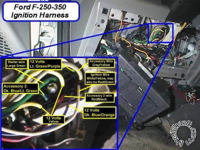
f250_ign.jpg------------- Amateurs assume, don't test and have problems; pros test first. I am not a free install service.
Read the installation manual, do a search here or online for your vehicle wiring before posting.
Posted By: bryan0129
Date Posted: December 14, 2015 at 12:02 PM
What is the purpose behind the thin orange wire on the 24 pin plug. It is a (-) 200mA Accessory Output.
Posted By: howie ll
Date Posted: December 14, 2015 at 12:08 PM
You have THREE accessory wires on that vehicle. #8 thick orange will power one.
After programming as described pink/white #4 will power the second.
Using the thin orange on the 24 pin plug will trigger the described relay to power the third.
-------------
Amateurs assume, don't test and have problems; pros test first. I am not a free install service.
Read the installation manual, do a search here or online for your vehicle wiring before posting.
Posted By: bryan0129
Date Posted: December 14, 2015 at 5:01 PM
Ok. Everything is wired according to what was discussed. Remote still says "Remote Start not available" when remote start is pressed. Is there something that has to be triggered to activate the remote start? Like I said earlier, the auxillery harness is barely used.
Posted By: howie ll
Date Posted: December 14, 2015 at 5:16 PM
You now have to learn tach program the unit for an auto if automatic transmission and set up for tach.
Start engine, within 5 seconds press and hold valet button. Blue light should come on on control centre, that means tach learned.
Change to auto.
Green from the 24 pin should be connected to door switches, if not ground for the following.
Open a door, turn ign. on and then off.
Within 5 seconds press and hold the valet switch. (on the antenna/control centre).
Siren should chirp once, then twice. then three times.
Release immediately then press once, release and hold. You should get 1 chirps.Keep pressing your "arm" button on the remote until you get 2 chirps.
Turn on and off ignition.
Green from the 24 pin should be connected to door switches, if not ground for the following.
Open a door, turn ign. on and then off.
Within 5 seconds press and hold the valet switch. (on the antenna/control centre).
Siren should chirp once, then twice. then three times.
Release immediately then press twice, release and hold. You should get 2 chirps.Keep pressing your "arm" button on the remote until you get 4 chirps.
Turn on and off ignition.
That's your lot follow my suggestions, it should work though I think you need professional help.
-------------
Amateurs assume, don't test and have problems; pros test first. I am not a free install service.
Read the installation manual, do a search here or online for your vehicle wiring before posting.
Posted By: bryan0129
Date Posted: December 14, 2015 at 5:45 PM
Progress, I guess. It activated, turned on accessories, did not attempt to start, then flash a low tach signal.
I have taken it to a shop. They said they would not finish someone else's project. I wouldn't blame them. I am just trying to fix this kids project since I bought the truck. Got a great deal on the truck though so I'm willing to go through some hassle for this. Lol.
Posted By: howie ll
Date Posted: December 14, 2015 at 5:47 PM
Try it with the key in the ignition, not turned on, just placed in the ignition. It's now nearly midnight my time so you won't get a reply for 8 hours or so but just humour me.
-------------
Amateurs assume, don't test and have problems; pros test first. I am not a free install service.
Read the installation manual, do a search here or online for your vehicle wiring before posting.
Posted By: bryan0129
Date Posted: December 14, 2015 at 7:26 PM
Nothing with the key in the ignition.
No worries about the time, I appreciate the help regardless.
Posted By: tactical-gears
Date Posted: February 26, 2016 at 10:10 PM
howie ll wrote:
Without looking too hard connect #9 with #2 and #6.
Did you mean connect all the 3 below together? I am trying to get a sense of how they'd go connected? Thanks
2 (+) Fused 12V Accessory/Starter Input - Linked with #6
6 (+) Starter Input (key side of starter kill) - On Starter wire before break
9 (+) Fused 12V Ignition 2/ Flex Relay Input 87 - Not Connected
------------- "Blessed is you who believes in the LORD"
Posted By: howie ll
Date Posted: February 27, 2016 at 12:16 AM
Yes.
-------------
Amateurs assume, don't test and have problems; pros test first. I am not a free install service.
Read the installation manual, do a search here or online for your vehicle wiring before posting.
Posted By: tactical-gears
Date Posted: February 27, 2016 at 3:52 PM
howie ll wrote:
Yes.
thanks howie, Can you check mine, i have the viper 5906v.... Would it apply to me too...And can i connect also the H1/1 Red (+) 12v Constant Input with the 3 below ?
H3/2 RED / White (+) Fused (30A) Ignition-2 / Flex Relay Input 87
H3/6 Red (+) Fused (30A) Ignition-1 INPUT
H3/9 RED / Black (+) Fused (30A) Accessory/Starter Input
Below is the wiring. Thanks
Main Harness, 6-pin connector
H1/1 Red (+) 12v Constant Input
H1/2 Black (-) Chassis Ground
H1/3 Brown (+) Siren Output
H1/4 WHITE/ Brown Parking Light Isolation Wire - PIN 87a of onboard relay
H1/5 White Parking Light Output
H1/6 Orange (-) 500mA Ground when armed
Door Lock 3-Pin Connector
(1.) Blue (-) 500mA Unlock Output
(2.) Empty NOT Used
(3.) Green (-) 500mA Lock Output
H3 Remote start 10 pin heavy gauge harness
H3/1 Pink (+) Ignition-1 Input/Output
H3/2 RED / White (+) Fused (30A) Ignition-2 / Flex Relay Input 87
H3/3 Orange (+) Accessory Output
H3/4 Violet (+) Starter Output ( Car Side of Starter Kill )
H3/5 Green (+) Starter Input ( Key Side of Starter Kill )
H3/6 Red (+) Fused (30A) Ignition-1 INPUT
H3/7 Pink/White (+) Ignition-2 / Flex Relay Output
H3/8 Pink/Black (+) Flex Relay Input 87A key side (if required) of FLEX RELAY
H3/9 RED / Black (+) Fused (30A) Accessory/Starter Input
H3/10 NC No Connection
Auxiliary/Shutdown/Trigger Harness, 24-pin connector
(1.) Pink/White (-) 200mA Ignition 2/Flex relay Output
(2.) Blue/White (-) 200mA Trunk Release Output
(4.) BLACK / YELLOW (-) 200mA Dome Light Output
(5.) Dark Blue (-) 200mA Status Output
(6.) WHITE/ Black (-) 200mA Aux 3 Output
(7.) WHITE/ Violet (-) 200mA Aux 1 Output
(8.) ORANGE / Black (-) 200mA Aux 4 Output
(9.) Gray(-) Hood Pin Input (NC or NO)
(10.) Blue (-) Trunk Pin/Instant Trigger Input
(11.) WHITE/ Blue Activation Input
(12.) Violet/White* Tachometer Input
(13.) BLACK/ White** (-) Neutral Safety Switch/Parking Brake input
(14.) GREEN/ Black (-) 200mA Factory Alarm Disarm Output
(15.) Green* (-) Door Output
(16.) BROWN / Black (-) 200mA Horn Honk Output
(17.) Pink(-) 200mA Ignition1 Output
(18.) Violet* (+) Door Input
(19.) Violet/Black (-) 200mA Aux 2 Output
(20.) Brown (+) Brake Shut down Input
(21.) Violet / YELLOW (-) 200mA Starter Output
(22.) Gray/black (-) Diesel Wait to start
(23.) Orange (-) 200mA Accessory Output
(24.) GREEN / WHITE (-) 200mA Factory Alarm Arm Output
------------- "Blessed is you who believes in the LORD"
Posted By: howie ll
Date Posted: February 27, 2016 at 3:53 PM
Same.
-------------
Amateurs assume, don't test and have problems; pros test first. I am not a free install service.
Read the installation manual, do a search here or online for your vehicle wiring before posting.
|