2005 CRV with Viper 5103 and DBALL2
Printed From: the12volt.com
Forum Name: Car Security and Convenience
Forum Discription: Car Alarms, Keyless Entries, Remote Starters, Immobilizer Bypasses, Sensors, Door Locks, Window Modules, Heated Mirrors, Heated Seats, etc.
URL: https://www.the12volt.com/installbay/forum_posts.asp?tid=140408
Printed Date: April 05, 2026 at 12:50 PM
Topic: 2005 CRV with Viper 5103 and DBALL2
Posted By: azndrgn
Subject: 2005 CRV with Viper 5103 and DBALL2
Date Posted: December 26, 2015 at 11:57 PM
Haven't installed a higher end RS system before but I've installed the cheaper box store ones on 90's era cars in the past. I've done all my homework and I think I've got it but I thought I'd post here with the hopes that someone could look things over for me and make sure I have it right.
Thanks in advance!!
Viper harness
H1/1 Trunk release-------> Black / Yellow wire in drivers kick panel 22 pin plug wire #16
H1/2 Constant 12V------> White wire in the ignition switch
H1/3 Horn-------> Orange wire in the factory alarm plug ( I don't have a factory alarm in this car so hopefully the plug is there)
H1/5 Chassis Ground -----> Grounded to body
H1/9 Dome light output -------->Green / red wire in drivers kick panel 22 pin plug wire #19 (*Any idea if this wire goes through a relay or if it's just direct power to the dome light?)
H1/11 Parking light-------> (+) Polarity RED / yellow wire in the dash fuse box 10 pin light green connector (G) pin #9 (*Anyone have a connector diagram?)
H3/1 Ignition 1 input / output ---->Black / yellow wire in the ignition switch
H3/3 Accessory output ------>Black / Red wire in the ignition switch
H3/4 Starter output -----> Black / White wire in the ignition switch
H3/6 Ignition 2 ----> White / Red wire in the ignition switch
RS input 5 pin connector
1 NSS-----> Chassis Ground
2 Tach input-----> Blue wire in the dash fuse box plug J pin #5
3 Brake shut down ----> White / black wire in Brake switch
4 Hood pin switch ------> Hood pin
5 Program for rear defroster ------> Yellow / Black wire in heater control unit plug. 30 pin green, pin #20
Door lock harness
1 Unlock output -----> White / green wire in the drivers kick 22 pin, #12
2 Not used
3 lock output -----> White / blue wire in the drivers kick 22 pin, #1
Replies:
Posted By: kreg357
Date Posted: December 27, 2015 at 5:04 AM
Looks pretty good. The Green factory alarm plug will be there. Besides the Horn wire, it will also have the
(-) Parking Light wire. I would use that (-) Parking Light wire instead of the (+) Parking Light wire. While those
two connectors in the DKP area ( alarm plug and Gray plug for the lock and trunk release wires ) are high up
and hard to get to, but easy to find and verify those needed wires.
Don't forget to connect the Red and RED / Black and RED / White wires in the H3 plug to the White +12V constant
wire in the ignition harness. The H3/6 ING2 output wire should be re-programmed for ACC2 operation being
as the CRV's WHITE/ Red wire is an accessory wire.
For the Tach wire there is a 2 pin test connector next to the battery in the engine compartment. Also easy to
find and you are running a wire through the firewall for the hood pin anyway... ------------- Soldering is fun!
Posted By: kreg357
Date Posted: December 27, 2015 at 5:51 AM
Addendum : The DB-ALL2 with 402.HONDA4 v3.06 will do more than just the transponder bypass. Looking at the Type 3 install diagram, it handles the trunk pop, locks and alarm ( if present ). It's slightly over-kill for this vehicle unless you have the factory alarm because everything is right there for hard-wiring. Think I would go with a less expensive bypass module like a PKH34 or XK05 w/PKH3 firmware.
------------- Soldering is fun!
Posted By: azndrgn
Date Posted: December 27, 2015 at 7:48 AM
Kreg,
Thanks for the quick reply! I'll add those 3 wires to the H3 harness to the white constant power wire, not sure why I omitted them in my notes. Thanks for the heads up on the DBALL2, I guess that's what inexperience will get you. The DEI site recommended that one so I went ahead and got it. I'm heading out to put it in so hopefully it'll all go smoothly from here on out.
Posted By: kreg357
Date Posted: December 27, 2015 at 8:44 AM
The DB-ALL2 is only a $15 difference and can save a few wire connections. If you have the DB-All2, make sure it was flashed with the correct Honda4 firmware.
-------------
Soldering is fun!
Posted By: howie ll
Date Posted: December 27, 2015 at 9:06 AM
You should be able to pick up tach at rear of gauges, blue wire.
Once you remove the instrument cluster you've got bags of room to mount both unit and DB-ALL, makes for a very neat and secure installation.
Anyone mention keysense or does the DB-ALL 2 handle this?
-------------
Amateurs assume, don't test and have problems; pros test first. I am not a free install service.
Read the installation manual, do a search here or online for your vehicle wiring before posting.
Posted By: kreg357
Date Posted: December 27, 2015 at 9:09 AM
Hi Howard,
Yes, the DB-ALL2 handles the locks, truck release and alarm.
-------------
Soldering is fun!
Posted By: howie ll
Date Posted: December 27, 2015 at 9:12 AM
Ta.
-------------
Amateurs assume, don't test and have problems; pros test first. I am not a free install service.
Read the installation manual, do a search here or online for your vehicle wiring before posting.
Posted By: azndrgn
Date Posted: December 27, 2015 at 9:13 AM
Yep, I got the XK Loader and I've flashed everything for the CRV. I'm running the DBALL 2 in W2W mode after reading some people having some communications issues, everything seems pretty straight forward but there is one wire that I want to verify. The Blue / White (-) GWR (status) Input from the the Dball2 I think should be tied to the Blue wire on the remote start auxiliary output 5 pin pin harness which is (-) 200ma status output, does that sound right?
Posted By: azndrgn
Date Posted: December 27, 2015 at 9:38 AM
Hmmm hadn't even thought of mounting the RS and DBALL behind the gauge cluster. I had them out the other night to change the back light bulbs, I'll have to pull it again and see what it looks like. Thanks for the tip!
Posted By: kreg357
Date Posted: December 27, 2015 at 9:39 AM
Yes, the GWR wire is AKA the (-) Status Output wire. In W2W mode join those two wires together.
-------------
Soldering is fun!
Posted By: azndrgn
Date Posted: December 27, 2015 at 10:54 AM
Just wrapping up my bench wiring before heading out to the car. Any recommendations on how I should terminate these unused wires? I started to cut little pieces of heat shrink tubing and seal each on individually but it takes a good bit of time to do that and I'm not sure that it's 100% necessary. Is cutting them short and taping the bundle together acceptable or is there concern that any of them will short together or to the chassis?
Posted By: howie ll
Date Posted: December 27, 2015 at 11:47 AM
Your first method whilst time consuming is best. Some people de-pin but that can be a real problem down the line if you either add things or want to remove and refit in another vehicle.
I find it perfectly acceptable to tape over provided you are using either Scotch 33+ or Tessa tape. Your 50c Walmart tape will unglue and fall apart within 4-6 months.
Here's a trick, de pin the power feeds (H3) pink/black and H1 white brown, you'll almost never need them.
The red, RED / black and RED / white on H3 plus the red on H2, solder together after their fuses so you have no more than two wires to solder at the end, far more convenient.
-------------
Amateurs assume, don't test and have problems; pros test first. I am not a free install service.
Read the installation manual, do a search here or online for your vehicle wiring before posting.
Posted By: azndrgn
Date Posted: December 27, 2015 at 1:54 PM
Most of the way through the install now and I've come up with a couple more questions. The DBALL2 wiring references tying into the immobilizer data wire which is pin 2 on the green 7 pin connector and the security light which is pin 5. I found the connector but can anyone verify the color of these wires? The keyless entry data wire is in green connector K on the back of the fuse / relay box, does anyone have a diagram that shows which connector is K?
Howie, I just saw your message and I've already done most of the connections with heat shrink and then taped them together to keep things neat. For all the splices I'm using scotch linerless rubber splicing tape. Do you have a wiring diagram for the gauge cluster? I'd like to try to get the tach wire connection at the gauges as you recommended if possible.
Posted By: howie ll
Date Posted: December 27, 2015 at 3:01 PM
Wire at back of gauge is blue. As for that plug, it's confusing, look carefully at both plug AND diagram. The U.K. market plug is even a different colour!
I've buggered a DB - ALL 2 doing that so be careful.
Are you soldering the joints?
-------------
Amateurs assume, don't test and have problems; pros test first. I am not a free install service.
Read the installation manual, do a search here or online for your vehicle wiring before posting.
Posted By: azndrgn
Date Posted: December 27, 2015 at 3:32 PM
howie ll wrote:
Wire at back of gauge is blue. As for that plug, it's confusing, look carefully at both plug AND diagram. The U.K. market plug is even a different colour!
I've buggered a DB - ALL 2 doing that so be careful.
Are you soldering the joints?
Yeah I think I've got the immobilizer wires figured out. Looks like the drawing is showing the plug as if you were facing the female connectors. I really wish they would give wire colors instead of just pin numbers, would make me feel a lot better about making the connection. Yes I am soldering all the joints.
Posted By: howie ll
Date Posted: December 27, 2015 at 3:34 PM
Good must solder. The vehicle colours are pastel and very vague.
-------------
Amateurs assume, don't test and have problems; pros test first. I am not a free install service.
Read the installation manual, do a search here or online for your vehicle wiring before posting.
Posted By: kreg357
Date Posted: December 27, 2015 at 5:49 PM
That why I like iDatalink, they always provide the wires' color and they are always accurate... Here is their info :
Ignition pin 6 BLACK / YELLOW (+) Ignition switch
Data pin 2 White (DATA) Ignition switch
Security Led pin 5 Blue/Orange
-------------
Soldering is fun!
Posted By: howie ll
Date Posted: December 27, 2015 at 6:20 PM
If you worked on Euro cars especially French, you'd know it's pin number EVERY TIME!
-------------
Amateurs assume, don't test and have problems; pros test first. I am not a free install service.
Read the installation manual, do a search here or online for your vehicle wiring before posting.
Posted By: azndrgn
Date Posted: December 27, 2015 at 7:54 PM
I ended up counting the pins and when I was looking through the instruction to get the DBALL to learn the bypass code I found the wire color codes in the back of the book.....
So I am 95% there with the installation, 2 wires left. the lock/ unlock data wire for the DBALL and the dome light wire for the Viper. I found the dome light wire but I am having trouble with the lock/ unlock data wire. According to the directions it is in the back of the fuse / relay box, 17 pin connector K. I can't really see the back of the panel under the dash so I have no idea where it is, any recommendation on where else I can find it? or an easier place to reach / tap it?
Posted By: kreg357
Date Posted: December 27, 2015 at 8:06 PM
More info from iDatalink :
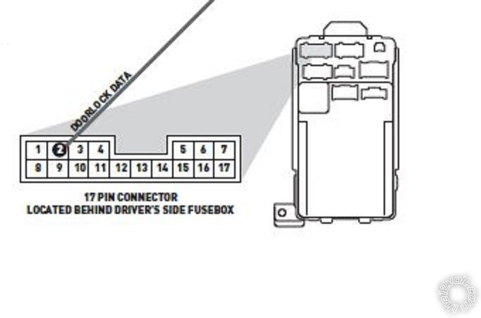
Looks like the top plug towards the center of the car.
Not sure I'd worry about Dome Light Supervision. Do the interior lights come on with an unlock command? ------------- Soldering is fun!
Posted By: azndrgn
Date Posted: December 27, 2015 at 8:35 PM
Hmm that looks like it'll be fun to get to. The dome light does come on when the stock unlock button is pushed, does that mean I don't need the dome light supervision light connected?
I think I had looked at an idatalink bypass when I started but I thought I had found that the firmware and wiring diagrams were not available to the general public. Do you have to be a dealer or one of their installers to be able to get to that information? If not I may need to try that out the next time I do this again.
Posted By: kreg357
Date Posted: December 27, 2015 at 8:55 PM
Probably don't need Dome Light Supervision connected.
iDatalink makes solid products. The install guides are very easy to follow and always very accurate. The install guides are available to all but their forums are restricted to registered and vetted professional installers. As with all major manufacturers ( Directed, Audiovox, Compustar, etc ) their Tech Support is available only to their dealers. ------------- Soldering is fun!
Posted By: howie ll
Date Posted: December 28, 2015 at 2:01 AM
Hello woken up late, two thoughts.
Dome supervision not required on Hondas, Toyotas BMW from around 2000.
That plug is a PITA to get at on right hand drive vehicles, alternative are plugs inside driver kick panel, but again in a recess, hard to see very thin wires, two plugs colours on Euro version again, don't match etc.
-------------
Amateurs assume, don't test and have problems; pros test first. I am not a free install service.
Read the installation manual, do a search here or online for your vehicle wiring before posting.
Posted By: azndrgn
Date Posted: December 28, 2015 at 9:04 PM
Thanks again guys. Between work and the weather it'll be a couple more days before I am able to get back to the car but I'll update this as I go along and hopefully when I'm done I'll be able to clean this up a bit so anyone who is looking to do this will have a decent reference to start with.
Posted By: azndrgn
Date Posted: December 31, 2015 at 2:27 PM
Okay well after 2 hours of cursing and finagling my way behind the fuse box I finally have the keyless entry wire hooked up but I think I may have fried by Dball2.... So the other night while I was trying to wrap up I accidentally connected the keyless entry wire from the DBALL2 to the dome light wire in the car. Is there any way to figure out if the DBALL is bad?
Fast forward to today the horn honks when I lock and unlock the car but the locks don't do anything. When I try to remote start the car I got 7 parking light flashes, manual transmission mode is enabled and not initialized. Reprogrammed the viper system to automatic transmission and now I get 8 parking light flashes, Neutral safety has no ground or the neutral safety switch is off. I've traced my wiring back and the neutral safety switch input, black / white wire, from the 5 pin remote start input wire is grounded to the body. Added another jumper to another ground and verified the ground with a multimeter and everything checks out. I've gone through the settings to make sure that I didn't miss anything but everything looks fine. I'm stumped, anyone have any ideas?
Posted By: azndrgn
Date Posted: December 31, 2015 at 3:23 PM
Okay so after some searching I found that not installing the shutdown toggle switch will give the NSS error. Plugged the switch in and the remote start works so at least the bypass still works. If I can't figure out the locks I guess I could remove the door lock wiring from the DBALL and just go straight to the lock and unlock wires on the car.
Posted By: azndrgn
Date Posted: January 03, 2016 at 2:15 PM
I haven't figured out a way to determine if my DBALL2 got fried when I hooked the lock / unlock data wire to the dome light I decided to take the lock and unlock wiring straight from the Viper brain to the car. I connected the blue viper wire to the white / green for the car for the unlock control and the green viper wire to the white / blue on the car for lock control. As soon as I touch the blue wire to the white / green the lock solenoids activate and go to unlock. With both wires temporarily connected the horn chirps and I hear a relay click but nothing else happens. Not sure what is going on so if anyone has any ideas I'm all ears.
Posted By: azndrgn
Date Posted: January 03, 2016 at 3:22 PM
Just checked out DEI's document 1041 and it looks like I should have a Type B system where the desired output is grounded. So on lock command the lock wire is grounded, on unlock command the unlock wire is grounded. I don't see any special setup required for it to do this and the diagrams I have show it hooked up the way I have it, Blue for unlock and Green for lock.
Posted By: azndrgn
Date Posted: January 03, 2016 at 7:32 PM
Well looks like DEI idiot proofed the wiring connections but I somehow still managed to screw it up. I had the door lock harness plugged into the black 3 pin plug instead of the white one. Swapped the harness and soldered the wires directly to the door lock wires on the car and everything works fine now. I didn't bother reconnecting to the DBALL but I imagine it is probably working fine. Only thing left is to finish programming. I really wish I had investing in a bitwriter now, listening to the horn honk over and over is driving me nuts and I imagine it's driving my neighbors crazy too.
|