’13 Tacoma CM7000AS with Blade Al
Printed From: the12volt.com
Forum Name: Car Security and Convenience
Forum Discription: Car Alarms, Keyless Entries, Remote Starters, Immobilizer Bypasses, Sensors, Door Locks, Window Modules, Heated Mirrors, Heated Seats, etc.
URL: https://www.the12volt.com/installbay/forum_posts.asp?tid=140695
Printed Date: April 19, 2026 at 1:40 AM
Topic: ’13 Tacoma CM7000AS with Blade Al
Posted By: jdmegcoupe
Subject: ’13 Tacoma CM7000AS with Blade Al
Date Posted: January 20, 2016 at 10:55 AM
Hello all,
I hope everyone is doing well. I am gonna give this a shot. Would anyone be able to help me with wiring a CM7000AS with a Blade AL into my 2013 Tacoma. Like a wire for wire write up. Please. I would like to get this done ASAP before the snow storm hits this weekend in Massachusetts.
Thank you.
I hope to hear back.
-------------
Replies:
Posted By: mscguy
Date Posted: January 20, 2016 at 12:01 PM
https://www.readyremote.com/main.asp?action=select&yr=26754&product=Remote%20Start&make=Toyota&model=Tacoma
Did your unit come with an install manual? It may even be written on the back of the 7000.
https://techfeed.compustar.com/ft_controllers/manuals/CM7000_Full_Install_3.00_EN.pdf
Your vehicle doesn't look very difficult. You'll need a relay for the 2nd starter wire.
Posted By: jdmegcoupe
Date Posted: January 21, 2016 at 6:47 AM
mscguy wrote:
https://www.readyremote.com/main.asp?action=select&yr=26754&product=Remote%20Start&make=Toyota&model=Tacoma
Did your unit come with an install manual? It may even be written on the back of the 7000.
https://techfeed.compustar.com/ft_controllers/manuals/CM7000_Full_Install_3.00_EN.pdf
Your vehicle doesn't look very difficult. You'll need a relay for the 2nd starter wire.
Thank you SiR! I got the cn1 figured out for the most part except on how to wire the FT-ELock. And the wiring for the cn5 has me a bit confused. -------------
Posted By: mscguy
Date Posted: January 21, 2016 at 7:14 AM
Did your 7000 come with an install guide? your ft-elock instructions are in there.
Posted By: jdmegcoupe
Date Posted: January 21, 2016 at 7:17 AM
I will have to check when I get home front work today! If I make template of what wires go to what wires can I pm it to you and you verify they are right before I begin?
-------------
Posted By: mscguy
Date Posted: January 21, 2016 at 7:24 AM
Just post on here so others can look too. Imo, it's always good to have more sets of eyes on something. I'm just a helpful diy'er so someone else may see something that I don't.
Posted By: jdmegcoupe
Date Posted: January 23, 2016 at 8:02 PM
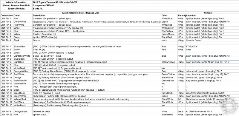
Okay Can anyone tell me if this is right? If the wiring is correct?Thanks
 -------------
Posted By: mscguy
Date Posted: January 23, 2016 at 10:52 PM
CN5 Pin 6 - YELLOW /GREEN. Ready remote says GREEN/ YELLOW. Check anyway
CN5 pin 9 - GREEN/ black Double (-) driver kick, gray 10 pin plug, pin 8
CN5 Pin 11 - Purple driver kick, gray 10 pin plug, pin 4
CN5 Pin 12 - Keysense. Idatalink guide says "Warning Don't connect keysense" to the starter. Not sure why, just going off the manual.
CN5 Pin 19. DON'T DO THIS the way you wrote. Your second starter is a positive connection. Connecting this to the small -250ma wire is a sure way to cook your module.
You need to use a relay to power this.
86 - +12V
85 - -250ma starter out CN5 Pin 19
87 - +12V fused.
30 - Car starter 2 wire. (BLACK/ white) ign harness
Other than these, it looks ok.
I'm getting my wires purely off the ready remote site. I'm not sure why some of yours are different. Please make sure to test all wires first.
Posted By: jdmegcoupe
Date Posted: January 24, 2016 at 1:42 PM
Okay I messed up writng the wires because I was tired last night. Fixed Let me know if this is all right now. Thank you

 -------------
Posted By: mscguy
Date Posted: January 24, 2016 at 6:25 PM
In that relay picture, you wrote CN1/3 to 87A, then 87A to starter side. If I'm reading your spreadsheet right, that will just send +12V constantly to your starter. Do you mean CN1/6 to 87A?
Cn5/9 still looks wrong. GREEN/ black (driver door key unlock) double - driver kick, gray 10 pin plug, pin 8
Other than that, I think it looks ok.
Posted By: jdmegcoupe
Date Posted: January 27, 2016 at 3:42 PM
Okay I installed it! Everything is working I think... I ordered a op500 because the one I had keeps saying err01 and I tried it on 3 cars. I need it to program the CM for the EZGO.
-------------
Posted By: jdmegcoupe
Date Posted: January 29, 2016 at 5:25 AM
Okay so I got my op500 and set everything up am I supposed to have both the RFID antenna plugged in to the Control module and the RF-2WSSL antenna for the remotes plugged in?
-------------
Posted By: kreg357
Date Posted: January 29, 2016 at 5:57 AM
The OP-500 will say ERR01 if the controller is in a "doors locked" status. Just press Unlock on one of the paired remotes and that error goes away.
-------------
Soldering is fun!
Posted By: jdmegcoupe
Date Posted: January 29, 2016 at 6:01 AM
kreg357 wrote:
The OP-500 will say ERR01 if the controller is in a "doors locked" status. Just press Unlock on one of the paired remotes and that error goes away.
I got that figured out. I am asking if I need to connect both antenna's to the control module for the remotes and the ezgo to work? -------------
Posted By: kreg357
Date Posted: January 29, 2016 at 7:49 AM
Haven't used an ES-Go yet but here is the info from the FT7000 Install guide :
Installing The FT-EZGO
STEP 1: Set Option 1-14 to Setting 2, 3 or 4
STEP 2: Connect included Blue 6 Pin (With Ground Wire) to Black 6 Pin to control module. If connecting
to a 4 Pin to 4 Pin antenna, use the included 6 Pin to 4 Pin adapter.
STEP 3: Connect the ground wire from the included 6 Pin to 6 Pin cable to vehicles ground. Warning:
Failure to connect this wire WILL result in damage to your FT-EZGO antenna (ANTRFID).
STEP 4: If you are using an additional RF kit the antenna cable will connect to the blue 6 pin connector
on the EZ-GO antenna either directly or using the 6 to 4 pin adapter harness included with the
EZ-GO kit.
STEP 5: Find a spot to mount your ANT-RFID on the windshield. This is recommended for optimum
range. For more specific mounting location information visit us at techfeed.compustar.com
under the Authorized Tech section document titled: FT-EZGO Recommended Mounting
Locations.
STEP 6: Program your EZ100-R using the standard remote programming procedure along with any
additional RF Kit remotes to the control module (Maximum 4 Remotes including EZ100-R). You
are now ready to test your FT-EZGO system.
------------- Soldering is fun!
Posted By: jdmegcoupe
Date Posted: January 29, 2016 at 7:54 AM
Okay so both antenna wires are connected to the CM7000. Then disconnect the cable at the antenna for the 2 way remotes and plug it into the open port on the RFID antenna. Then program the remotes and the ezgo remote to that antenna. Correct?
-------------
Posted By: kreg357
Date Posted: January 29, 2016 at 9:01 AM
That's not the way I read it. On the older CM6x00 units, you did not want to plug in two antenna's ( 4 Pin and 6 Pin ) at the same time. That also included the OP-500 programmer in the 4 Pin port and an antenna on the 6 pin port. Seems like the EZ-Go plugs into the CM7x00 and the antenna plugs into the EZ-GO's blue 6 pin port. But like I said, I haven't used an EZ-GO yet...
-------------
Soldering is fun!
|