2008 Ram Diesel Remote start
Printed From: the12volt.com
Forum Name: Car Security and Convenience
Forum Discription: Car Alarms, Keyless Entries, Remote Starters, Immobilizer Bypasses, Sensors, Door Locks, Window Modules, Heated Mirrors, Heated Seats, etc.
URL: https://www.the12volt.com/installbay/forum_posts.asp?tid=140819
Printed Date: April 02, 2026 at 9:51 AM
Topic: 2008 Ram Diesel Remote start
Posted By: rayacain90
Subject: 2008 Ram Diesel Remote start
Date Posted: February 09, 2016 at 10:21 AM
Good Morning,
I just recently installed an Avital 5303L remote start in a 2008 Dodge Ram Diesel. Everything seems to work fine except for the starting part. When I press the remote start button I can see the ignition go to "ON" but it does not even try to crank.
I have a couple ideas on what the issues might be but I need help in determining it.
I know the Chrysler vehicle have the immobilizer system and the key has to be in the ignition, until I get the bypass module which is on the way. So, the question I have about that is, does anyone know if it can be remote started with the key in the ignition without the bypass module? Or does it HAVE to have the bypass module to start remotely? Of course having the key in the ignition is not what I intend to do but I am trying to troubleshoot it until the bypass arrives.
Also, I tapped into the Tach wire off the ECM. Going by the factory service manual I got the right wire. Looking online though I saw a trustworthy site mention that on diesels specifically it was pin 24 on the 60 pin connector. With the engine running should I see a rise in voltage on that wire when it revs? Does it need to receive a signal on that wire to remote start?
Once I get this together and worked out I plan to do a full write up on it since the instructions that came with it aren't very helpful and I had to scour the internet for bits and pieces to help me out.
Thanks for the help!
Replies:
Posted By: kreg357
Date Posted: February 09, 2016 at 1:15 PM
I don't want to assume anything here so I will ask probably dumb questions.
First off, placing the key in the ignition switch ( but not turning it ) is a good way to verify the remote start install before
adding in the bypass module.
Next comes the trucks ignition wires. The only wire you will directly apply power to is the Ignition wire. So Viper thick
Pink IGN1 to RAM thin Pink/White.
The rest is handled by the trucks PURPLE / Brown wire in MUX fashion. For this, you will follow the DEI Tech Tip 1084.
Here is a link : https://www.the12volt.com/installbay/file.asp?ID=517
Here is the diagram with the variables filled in :
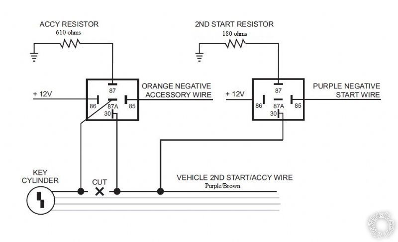
Did you do this circuit?
For the Diesel Tach wire, here is some info from ReadtyRemote :
On diesel models, the Tach wire is at the ECM on the lower driver side of the engine, front 60 pin plug, pin 24,
or at the camshaft position sensor just left of the ECM, in a 3 pin plug.
Sounds like you have the correct wire. To verify this wire, connect a Digital Multi Meter as follows :
DMM set to 20V AC. Red test lead to the suspect wire. Black test lead to solid chassis ground or Negative battery
terminal. With engine idling, you should see 1 to 5 volts. This voltage should rise slightly with added RPM's.
Did the Avital successfully perform the Tach Learn? ------------- Soldering is fun!
Posted By: rayacain90
Date Posted: February 09, 2016 at 2:35 PM
Thanks for the reply!
You assume correct because those aren't dumb questions for me!
This is my first major electrical install in the automotive area.
So, I had thought of placing the key in the ON position and trying from there but I didn't want to risk damaging anything. Now that it seems that's safe to do I will do that.
As far as the 12v constant. The ignition wire is the only one that I supplied 12v to.
When building that circuit I followed the instruction for splicing in the Satellite Relay Terminal. Looking at it it looks like how I wired it up. I'm not 100% sure those resistors are present on those grounds however since it is all internal. I can do some testing when I get home.
"On diesel models, the Tach wire is at the ECM on the lower driver side of the engine, front 60 pin plug, pin 24,
or at the camshaft position sensor just left of the ECM, in a 3 pin plug."
I saw that same thing on one website. However looking at the FSM and seeing a couple posts by Dodge techs the correct pin is 37 on the connector. Pin 24 in the FSM for the 6.7L is labeled Engine Cooloant Temp.
I did put a DMM on it and it was resting at 3.5v when idling. However it did not raise when the rpm's increased. I also just noticed that the voltage is AC not DC and that may have effected it since the MM was set to VDC I will try that test again.
Posted By: rayacain90
Date Posted: February 09, 2016 at 2:39 PM
Yes, according to the LED it did learn the tach signal.
Posted By: kreg357
Date Posted: February 09, 2016 at 3:06 PM
Those relays for the PURPLE / Brown MUX wire are external, extra relays that you supply. I'm not a DEI user and not real familiar with the 5303L R/S, but if it has an external satellite relay pack, those relays are all +12V outputs and wired that way. Probably take a bit of re-wiring to change the Starter and Accessory relay over to the (-) plus correct resistance output needed for the trucks MUX wire. Notice that in the diagram above that the relays output is Chassis Ground through the resistor. Not a positive voltage through a resistor.
All this might be somewhat moot. Most of the newer bypass modules for this application do not need external relays for the MUX wire. They have that function built-in. What bypass module did you order?
If you want to start it up, try this : Get a 180 ohm 1/4 watt resistor some wire and alligator clips. An alligator clip on each end of the wire with the resistor in the middle, nicely soldered. Connect one alligator clip to solid chassis ground. Put the key in the ignition cylinder but don't turn it. Hit the remote start button. Wait until the instrument cluster lights up and then touch and hold the other end of the alligator clip to the PURPLE / Brown wire until the engine cranks and starts, then remove the alligator clip. That's with a warm engine because you aren't doing a delay for the glow plugs to warm things up... ------------- Soldering is fun!
Posted By: rayacain90
Date Posted: February 09, 2016 at 4:42 PM
I ended up ordering the XK09 off Bulldog Security.
I decided not to deal with the wait-to-start feature at the moment. There is no wire going to the instrument cluster for the wait-to-start light. I believe the ECM just sends pulses over the CAN bus to tell it when to turn on/off. For the moment i'm just going to use the delay start feature. I do believe however that I can just tap into the low current side of the relay that activates the grid heater (glow plugs). Since it has voltage when the light is on and goes to ground when the light is off.
Posted By: kreg357
Date Posted: February 09, 2016 at 5:11 PM
The XK09 module flashed with the Chrysler v3.02 firmware will handle the MUX ignition wire, no need for external
relays & resistors and the Tech Tip 1084 diagram. The XK09 will also handle the transponder bypass and the
locks/factory alarm. Just follow the Type 3 wiring diagram and you are all set. Not sure if the XK09 can supply a
Tach signal on a diesel.
You can program the 5303L for a fixed 15 second start delay for the glow plugs if you don't want to go through
the trouble of wiring up a WTS input signal.
Might as well wait for the XK09 because the wiring you have done will change with the addition of the bypass module. ------------- Soldering is fun!
Posted By: rayacain90
Date Posted: February 09, 2016 at 5:18 PM
That's what I was planning to do, wait until I get that wired up.
I think I can get the tach figured out. As long as i'm sure I get the right wire.
I'll probably try and get the wait to start hooked up down the road though. Just to have it functional.
Thanks for all the help!!
Posted By: rayacain90
Date Posted: February 14, 2016 at 12:14 PM
I got the XK09 in and out of the box. Looking through the instructions that came with it it looks pretty easy to wire up. However, it's instructions and the 5303 instructions doesn't say this but I get a feeling I don't use the "Heavy gauge relay satellite terminal" box at all????
Can anyone confirm or deny that? I have searched and cant really find anything.
Thanks!
Posted By: kreg357
Date Posted: February 14, 2016 at 9:27 PM
First, make sure the XK09 was flashed with the 9.Chrysler v3.02 firmware. The XK09 can be flashed with many different
firmwares, depending on the vehicle application.
As for using the satellite relay pack, you will need it. How much you need it depends on whether or not you will be going
D2D or W2W between the Viper and the XK09. If you decide to go D2D and use the supplied DBI D2D harness between
the two modules, all the dash blue line will be made via the D2D harness. This will save you some inter-module wiring.
If everything works as advertised. great. If not, then not so good. If you decide to go with W2W, then all the necessary
connections must be hardwired.
Anyway, the truck and the XK09 both need to see a (+) Ignition signal. The XK09 can get it via the D2D harness but you
will have to make a hardwire connection to the truck, as shown in the Type 3 diagram. If you go W2W, this Ignition wire
and the (+) Starter wire will have to be hardwired as shown. ( Your truck does not have a separate Starter wire, just the
Starter MUX wire, that is handled by the XK09. )
Remember that the Type 3 diagram is somewhat generic with regards to the Remote Starter. Some R/S units have
an external relay pack and others don't. Some have a Neutral Safety wire and others don't. Your truck has no need
for a Trunk Release or Trunk Trigger Input. Additionally, the Type 3 Diagram does not show all the necessary wires /
connections. Notice that the very important (+) Brake wire is not even shown at all. ------------- Soldering is fun!
Posted By: rayacain90
Date Posted: February 14, 2016 at 9:33 PM
I'm stuck now...
I have the RS and XK09 wired up as the instructions say.
I still get no attempt to crank however when I try to remote start. I'm not sure on two of the wires on the heavy Gauge relay satellite though.
H/1 PURPLE -- Starter output to starter (starter side)
H/2 GREEN -- Starter input from ignition switch (key side)
The 2008 Dodge RAM 2500 Diesel has a VT/BR wire that all the websites and the manual says is used as the 2nd starter/MUX wire. It comes out of the ignition connector and goes back into the immobilizer connection above the key cylinder. So, im not 100% sure which is the ignition side and which is the starter side. Right now I have the GREEN wire going into the ignition module and the PURPLE going into the immobilizer.
Posted By: rayacain90
Date Posted: February 14, 2016 at 9:56 PM
I think I posted that as you replied to the last one.
Bulldog Security called me and asked for the vehicle info so they could flash it. So I assume it has the right one on it.
I am trying to get it going using the D2D connection.
The VT/BR MUX wire is a negative output. I need to turn that into a positive output correct? The XK09 instructions say do not connect the yellow and brown wire (ignition and 12v) if there is no 12v starter wire on pin 4. Well, my ignition connector doesnt match exactly to their instructions but I dont have a 12v starter wire, unless its referring to the MUX wire. So I didnt hook those two wires up.
Is there a way to verify it has the correct firmware on the XK09?
Posted By: mscguy
Date Posted: February 14, 2016 at 10:58 PM
Just throwing this out there, but have you connected H/3 and H/6 on the heavy gauge harness? If you need a hardwired ignition connection to the vehicle using The Heavy gauge H/5 Pink, isn't that power coming from one of those 2 Fused leads?
As for your MUX wire, I don't see any polarity designation on the XK09 diagram, and ready remote shows your mux wire as a (-) anyway. I would assume the correct firmware would account for this.
Also, at this point, I wouldn't even connect your starter purple and green wires at all. You don't have a dedicated starter wire to use them on anyway. I may be wrong on that, but maybe Kreg can correct me.
Posted By: rayacain90
Date Posted: February 14, 2016 at 11:04 PM
Hmmm, so you are saying don't use H/1 and H/2 at all?
I do have H/3 and H/6 connected as well. All the heavy gauge wires are connected currently.
I'll try not using the starter wires and see how that goes.
Posted By: mscguy
Date Posted: February 14, 2016 at 11:14 PM
Also, did you connect your Neutral Safety wire?
Posted By: rayacain90
Date Posted: February 14, 2016 at 11:25 PM
Yeah, that's grounded.
Posted By: kreg357
Date Posted: February 15, 2016 at 5:39 AM
Yes, MSCGUY is correct. The only output wire on the relay satellite pack you need in D2D is the Pink Ignition 1 output.
But you still need to give the relay pack +12V input power. The install guide doesn't list exactly which pins do what, but
you can combine all 3 +12V input wires ( H/3, H/6, H/8 ) into one wire with one 15 amp fuse and connect that to a suitable
+12V power source. With your truck and its' unique ignition wiring, you really can't use the Starter Kill and Anti-Grind
functions of the H/1 and H/2 Starter wires. Don't try to connect them. All you need is Ignition and the PURPLE / Brown
Starter MUX wire to run that truck. The XK09 handles the PURPLE / Brown Starter MUX wire, so no connections to it from
the relay pack. As a re-cap, on the Heavy Gauge wires from the relay pack, the only wires used / connected are the
Pink, Red, Red, RED / White. All the rest, Purple, Green, Orange, Pink/White are NOT used and NOT connected.
The only way to verify the firmware loaded onto the XK09 is with the XKLoader2 cable. You can find them on-line for
under $30.
Beside the Neutral Safety wire, did you connect the Viper's Brake wire to the truck? ------------- Soldering is fun!
Posted By: rayacain90
Date Posted: February 15, 2016 at 10:46 AM
I have the +12v wires (H/3, H/6, H/8) all connected to a power source straight off the battery. I'll disconnect the starter wires from the relay pack. That makes sense why you wouldn't use them after MSCGUY mentioned it:)
I have the brake interrupt connected and it is working great to shut down the remote start as it keeps cycling through trying to start it.
It's the MUX wire that is confusing me. The Avital instructions say cut that wire and one end goes to the green heavy gauge wire and the other goes to the purple on. Since I am not using those do I NOT cut that way and just splice the MUX wire from the XK09 into it?
I'm confident that the other wires are connected correctly with the exception of those unnecessary connections on the relay terminal and the PURPLE / Brown MUX wire.
I'll focus on that area today.
Posted By: rayacain90
Date Posted: February 15, 2016 at 11:32 AM
Also on the immobilizer I only have to make two connections, one to the CAN BUS HIGH and one to CAN BUS LOW. I measured the voltage on both of these and one is what I saw on all the other data connections (5v). The other is .5v. Is that what is means by high and low? Because if that's the case I have them backwards, however I have them connected as the instructions and the FSM say. Could they be swapped?
I have connected all wires as you guys mentioned now I am working on getting the XK09 to talk to the RS which doesn't seem to be happening properly.
I go by the instructions to reset the XK09 module and when I plug it back it the LED goes solid for a few seconds and then goes out and I cant get it to do anything after that. I insert the key, turn it to on and wait but get nothing.
Also, could low battery voltage effect the starting system? I know that sounds like a stupid question but I can start it with a key. It's somewhat a weak crank but it will start. I have been getting a check engine light for low battery voltage though. Could the RS trying to do it be to much to crank the starter if the batteries are getting weak? I have it set to a 15 second delay and it seems fine while it waits. No dimming lights or anything.
Posted By: mscguy
Date Posted: February 15, 2016 at 11:35 AM
Don't cut the PURPLE / brown. Just connect to it in parallel.
I can understand why the starter cutoff is confusing when you read the Avital directions. Most vehicles have an actual wire whose sole purpose is for the starter, and it's pretty cut and dry.
You have a wire that doesn't actually do anything, except connect to a computer that will make different things happen depending on the resistance it sees. In your case, it is a starter wire, accessory, and key sense. The xk09 wire will show those different resistances to the computer to tell it what to turn on.
If you really want to have a starter kill, you can find the starter solenoid wire (assuming you have one somewhere) and interupt that one, but I wouldn't worry about that right now.
Posted By: rayacain90
Date Posted: February 15, 2016 at 11:49 AM
I'm not really worried about a starter kill. Just getting it started would be nice.
So, I missed the part in the resetting the XK09 instructions where you need to hold the programming button and wait for the LED to flash before you release it.
Once I did that and followed the troubleshooting for programming it it seemed to take it fine based on the LED activity. However after that was done I didn't get any activity out of the LED while it was sitting idle or while it was trying to start the truck.
|