Push Button Start, Reverse Polarity Lock Actuator
Printed From: the12volt.com
Forum Name: Car Security and Convenience
Forum Discription: Car Alarms, Keyless Entries, Remote Starters, Immobilizer Bypasses, Sensors, Door Locks, Window Modules, Heated Mirrors, Heated Seats, etc.
URL: https://www.the12volt.com/installbay/forum_posts.asp?tid=140866
Printed Date: April 02, 2026 at 11:06 PM
Topic: Push Button Start, Reverse Polarity Lock Actuator
Posted By: 1967ls2
Subject: Push Button Start, Reverse Polarity Lock Actuator
Date Posted: February 17, 2016 at 1:06 PM
I have a 1967 Camaro that I installed electric door lock actuators in so I can use a remote to lock and unlock my doors and trunk. I also purchased a push button start system from Innovative Ignition Systems (On a side note, never purchase anything from this company. They have the absolute worst customer service, no phone number so you can't speak to anyone, and everything is done through email with weeks in between for response time.) The wiring diagram for the push button start system calls for the GREEN/ black wire to be wired to "Unlock Signal (+)" and the blue/black wire to be wired to the "Lock Signal (-)". I have already confirmed that the two wires leading to the door lock actuator reverse polarity depending on whether it is being locked or unlocked. With that in mind, how am I suppose to wire the push button start system? Do I need to run some relays here? 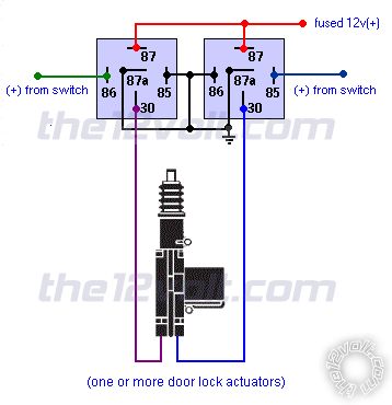 I was provided the reverse polarity wiring diagram from the tech at Innovative Ignition Systems but it looks like there is a lock signal (+) coming out of both relays.
I assume if I hook up the Unlock Signal (+) to the positive wire when I unlock the door, this will activate the push button start system so I can get in the car, push the button and start. But if I lock the doors once the car is started, the polarity to the unlock signal (+) wire will become (-), so will my car turn off?
I'm just trying to figure out how to wire this thing so when I unlock the door, I can get in and push the start button to start the car. When I am in the car, I will also like to lock the doors with the same remote without my car turning off. When I exit the car, I want to ensure that the push button start system is deactivated so if someone breaks into my car, they can't just push the start button and drive off. Please let me know if there are any suggestions or if I need to provide any other information, documents, pictures, diagrams, etc. Thank you in advance for the help! 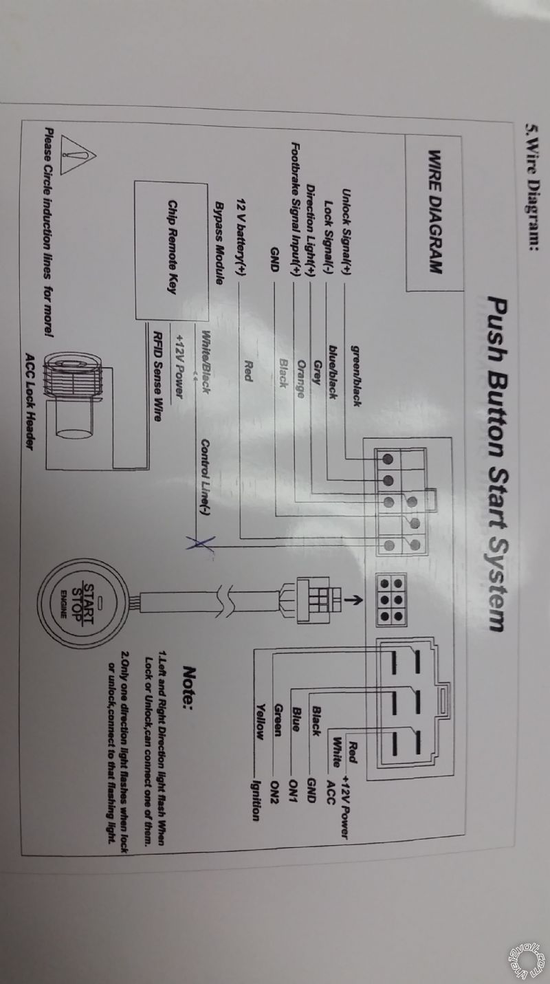
Replies:
Posted By: the12volt
Date Posted: February 17, 2016 at 11:00 PM
I think you're saying the push button start system is dependent on the lock and unlock signals to enable and disable the push button, correct?
If that's the case, the positive unlock lead and the negative lock lead from the push button system would connect to the same wire going to your door lock actuators (positive during unlock, negative during lock). I would use diodes just to be safe. One issue you may have is with locking the doors after you enter or start the vehicle if you're using a switch or remote, but we can come up with a solution for that.
Do you have a link to the complete manual for the push button start system or a copy you can upload to this site?
I'd like to know how your system is supposed to work and what is required for it to work properly. -------------  the12volt Support the12volt.com the12volt Support the12volt.com
Posted By: the12volt
Date Posted: February 17, 2016 at 11:02 PM
One more thought, what keyless entry system are you using? ------------- the12volt Support the12volt.com
Posted By: 1967ls2
Date Posted: February 18, 2016 at 12:00 AM
Thank you for the response.
Correct, the push button start system is dependent on the door lock actuator system. The door lock system is from klassic Keyless.
So your saying I should connect the Unlock Signal (+) and the Lock Signal (-) to the same wire on the door lock actuator?
Wouldn't the push button start system be receiving mixed signals? It would be receiving both an unlock and lock signal at the same time.
My understanding is that when the Unlock Signal (+) is receiving a (+) signal it activates the push button start system and the Lock Signal (-) would be grounded.
The rest of the push button start system instructions only discuss operation, like press the brake once and push the button to turn on the car. Press the brake twice and hold the push button for five seconds to activate the accessory only. I'll take some pics of the rest of the instructions but what I uploaded is all there is for "installation" instructions. Kind of lame.
Posted By: the12volt
Date Posted: February 18, 2016 at 9:33 AM
The unlock (+) and lock (-) are the same wire on the actuator, however each wire of the actuator rests at ground (-) in the diagram above.
I'll assume the push button start system is looking for a pulse from your keyless entry system. On most keyless entry systems the two door output wires provide a negative and positive pulse during lock and a positive and negative output during unlock on the same two wires.
Example: the two keyless entry door lock/unlock output wires are blue and green. During lock, the blue wire sends a positive pulse and the green wire sends a negative pulse. During unlock, the blue wire sends a negative pulse and the green wire sends a positive pulse.
Again, you would be connecting the push button start system's unlock signal (+) and lock signal (-) to only one of the two output wires from the keyless entry. In the example above, they would both connect to the green lock/unlock wire from the keyless entry.
What keyless entry system are you using?
A complete copy of the push button start's manual might be helpful. ------------- the12volt Support the12volt.com
Posted By: 1967ls2
Date Posted: February 18, 2016 at 12:29 PM
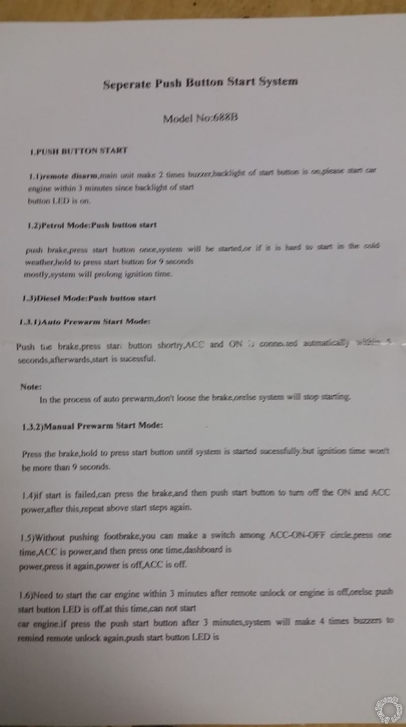
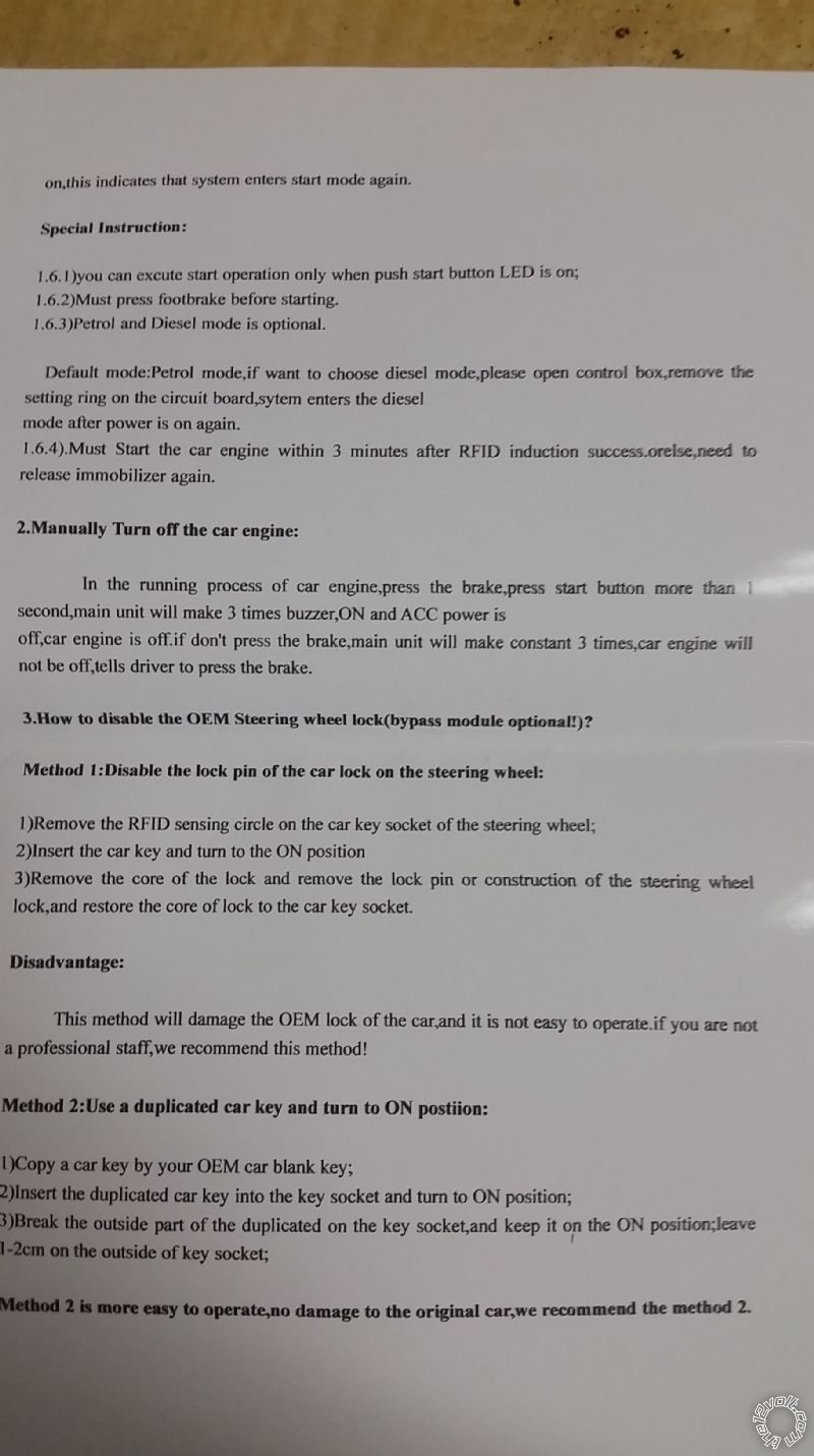
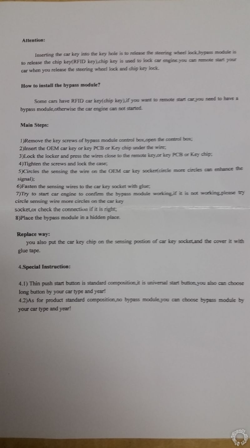
These are the remaining directions that were received with the push button start system. One page is for a bypass module but that doesn't apply to my setup since it is being installed on a 1967 Camaro with no such feature. The electric door lock system was from Klassic Keyless. So far the door lock system works great.
As you can see from the attached directions for the push button start system, they discuss function of the system as opposed to installation. I hope this is helpful. At first glance of the directions it looks like it was translated from Chinese to English by someone who doesn't have a firm grasp on the English language.
I think I'm picking up what you are laying down.
I tested the door lock actuator wires before I put my door panels back on. There is a blue wire and green wire running to the door lock actuator. When I hit the lock button the blue wire has power. When I hit the unlock button the green wire has power.
If I understand correctly, the system only sends a pulse of electricity through the green wire to unlock the door. When I hit the lock button the system sends a pulse of electricity to the blue wire to lock the door. When one wire receives a (+) signal the other wire is grounded. After each cycle, both wires are resting in a (-) state.
Your suggestion is to hook up the Unlock Signal (+) GREEN/ black wire from the push button start system to the green wire on the door lock actuator correct? This way when the unlock button is pressed on the remote, the green wire on the door lock actuator receives a (+) signal thus triggering a (+) signal to the Unlock Signal (+) GREEN/ black wire on the push button start system. I would then assume that the push button start system computer control would only need that single (+) signal to activate and turn on in a ready state so when I get in the car, I simply push the start button to turn on the car.
You also suggest hooking up the Lock Signal (-) blue/black wire from the push button start system to the same green wire on the door lock actuator correct? This way when the lock button is pressed on the remote, the green wire on the door lock actuator receives a (-) signal thus triggering a (-) signal to the Lock Signal (-) blue/black wire on the push button star system, correct? I would then assume that the push button start system computer control would only need that single (-) signal to deactivate and turn off the power to the push button start system so when I try to push the start button there is no power and thus the car will not turn on.
But that would mean that both the Unlock Signal (+) and Lock Signal (-) would receive the same (+) signal when the door is unlocked and the same (-) signal when the door is locked, correct? My only question would be whether or not that screws with the computer that controls the on/off function of the push button start system. Not sure if it would but I guess trial and error would tell.
I am just hesitant to connect both wires to the same door lock actuator wire and they both receive a (+) and a (-) signal at the same time. I wouldn't want to fry the computer control module or anything.
I would also be concerned that if it was hooked up as discussed above, what would happen if I turned the car on and then used the same remote to lock the car doors? Would the car die? I guess I could manually lock the doors but that would prove to be a hassle. I guess I could always wire a different fixed button somewhere in the car that would have lock and unlock the doors?
I greatly appreciate your assistance with working through this with me. I just want to make sure I know where I am wiring everything before I cut apart my harness so that I can make this process as smooth as possible.
Posted By: the12volt
Date Posted: February 18, 2016 at 12:45 PM
Before I read the manual and the rest of your post, do not hook up any wires from the push button start to the actuator wires. The blue and green wires I was referring to in my previous post is from a keyless entry system that would go to a pair of relays as shown in the first diagram you posted.
I'll post back as soon as I get a chance to read through your last post. ------------- the12volt Support the12volt.com
Posted By: 1967ls2
Date Posted: February 18, 2016 at 12:54 PM
Thanks for the fast reply. I am not working on the install now as there are still unknowns on my end. I will wait for your response once you have time to read through everything.
Posted By: the12volt
Date Posted: February 18, 2016 at 1:01 PM
Please read my post about the remote keyless entry door lock outputs again. Only one wire from the keyless entry supplies a negative output while the other supplies a positive output during one operation, whether it is during lock or during unlock.
The push button start system needs to see the lock and unlock signals from a remote keyless entry system, not the actuator.
What remote keyless entry system do you have?------------- the12volt Support the12volt.com
Posted By: the12volt
Date Posted: February 18, 2016 at 1:05 PM
Are you saying the remote keyless entry system is from Klassic Keyless or is it just the door lock system? If it is the remote keyless entry system, please post the manual for it. ------------- the12volt Support the12volt.com
Posted By: 1967ls2
Date Posted: February 18, 2016 at 1:08 PM
I understand that the remote keyless entry door lock system supplied a negative output while the other supplies a positive output during one operation. There are two wires leading to the actuator (Blue and Green), when the doors are unlocked the green wire has power and the blue wire is negative. When I lock the doors, the blue wire has power and green wire is negative.
The remote keyless entry system is from Klassic Keyless. https://www.klassickeyless.com/
Posted By: 1967ls2
Date Posted: February 18, 2016 at 1:13 PM
Correct. The remote keyless entry system is from Klassic Keyless. It came with the door lock actuators, wiring, computer control module and two remotes.
I will get the installation instructions and post up.
Posted By: the12volt
Date Posted: February 18, 2016 at 1:23 PM
I just took a peek at the keyless entry system on the site you posted and it appears the receiver connects directly to the actuators to minimize wiring (all in one unit, err). If this is the case, you will need to add relays to get the signals you need and isolate them from the actuators or you will have to see if you can solder leads directly to one side of each relay coil for lock and unlock signals inside the unit.
I'll wait for you to post the manual before we move on, but now I'm pretty sure I understand the confusion. The leads appear to be going directly to the actuators from the remote keyless entry system in the photo on their site. ------------- the12volt Support the12volt.com
Posted By: 1967ls2
Date Posted: February 18, 2016 at 1:45 PM
I requested a copy of the Klassic Keyless installation manual for the keyless entry system from Klassic Keyless just now.
I believe I still have the installation manual at home so if I don't receive it by email today I will dig it up tonight when I get home.
Yes, the receiver connects directly to the actuators. I'll post the manual once I get it.
Posted By: the12volt
Date Posted: February 18, 2016 at 1:55 PM
Since they are coming directly from the remote keyless entry module, I won't need it. I'll draw up a diagram for you in a bit.
Do you also have a switch (or switches) in the vehicle to control the door locks? ------------- the12volt Support the12volt.com
Posted By: 1967ls2
Date Posted: February 18, 2016 at 2:02 PM
No there are no switches to control anything. I only have the remote to unlock and lock the doors. The remote also controls the trunk lock.
I would like to have a button somewhere in the car to lock and unlock the doors and trunk as opposed to using the remote even when I am in the car. I don't think it would be too difficult to wire it up down the road though.
Posted By: 1967ls2
Date Posted: February 18, 2016 at 3:51 PM
Awesome, thank you so much for the diagram! Any suggestions as to where I should purchase the SPDT relays?
Right after the diodes you have a green and blue wire that says "(+) from switch." Are these supposed to go to a switch that locks and unlocks the doors when in the car?
Posted By: the12volt
Date Posted: February 18, 2016 at 3:56 PM
I had posted a diagram earlier, but realized the outputs of the remote keyless entry system most likely rest at ground, so here is an updated diagram.
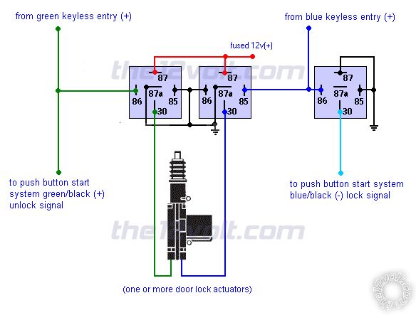
You will need three SPDT relays. Disconnect the actuators from the keyless entry module and connect the wires from the actuators, from the keyless entry module, and to the push button start system as shown above. The keyless entry system will no longer be connected directly to each actuator.
This will provide the positive unlock and negative lock signals to the push button start system from the keyless entry module.
If you add a door lock switch in the future, you will need two additional relays to isolate the door lock switch from the keyless entry module and to prevent it from interfering with the push button start system. When you're ready for that, let know and I'll draw another diagram. ------------- the12volt Support the12volt.com
Posted By: the12volt
Date Posted: February 18, 2016 at 4:00 PM
1967ls2 wrote:
Awesome, thank you so much for the diagram! Any suggestions as to where I should purchase the SPDT relays?
Right after the diodes you have a green and blue wire that says "(+) from switch." Are these supposed to go to a switch that locks and unlocks the doors when in the car?
Ignore the first diagram I posted with the diodes and inputs from the future door lock switch. See the post above.
You can find a link at the bottom of this page to purchase relays.
https://www.the12volt.com/relays/relays.asp------------- the12volt Support the12volt.com
Posted By: 1967ls2
Date Posted: February 18, 2016 at 4:08 PM
Just reviewed. The second diagram looks less complicated. I agree that getting the system to function properly first would be best then following up later to add a physical switch inside the car to lock/unlock can follow.
Do you have any suggestions as to where to purchase the SPDT relays? I just want to make sure I order the correct ones and that I order ones that are reputable and wont die after a short period of time.
Thank you so much for all of your help with this. I can't tell you how much I appreciate it. The company I purchased the push button start system (innovative ignition system) assured me before the purchase that they were there to assist along the way with all the questions I had and they also assured me the system I purchased would work fine with the keyless entry system I had already installed. Obviously there is more work that needs to be done.
Posted By: 1967ls2
Date Posted: February 18, 2016 at 4:13 PM
I just saw the rest of your post to purchase the relays! Thank you!
Posted By: the12volt
Date Posted: February 18, 2016 at 4:24 PM
Here is a diagram with inputs from a future switch which will require two more relays due to the fact that your keyless entry system outputs likely rest at ground.
 ------------- the12volt Support the12volt.com
Posted By: the12volt
Date Posted: February 18, 2016 at 4:26 PM
1967ls2 wrote:
I just saw the rest of your post to purchase the relays! Thank you!
You're welcome! ------------- the12volt Support the12volt.com
|