i have 96 ford f150 im trying to wire up they keyless entry to the door lock i have printed the diagram for the colors and such but the 5 wire door locks are confusing me the truck does not have the rke entry box so im using after market here is the diagram for the after market unit my intentions is to run everything thru the door jam and connect at kick panel
-------------
wes5314
Couldn't tell from your post but I'm assuming the F150 has factory power door locks but not the Factory Remote
Keyless Entry. Here is the vehicle lock wiring info from this site :
Door Lock Pink / YELLOW Passenger's Kick, w/o Keyless Reverse Polarity, use Driver's Switch to Test
Door Unlock Pink/Light Green Passenger's Kick, w/o Keyless Reverse Polarity, use Driver's Switch to Test
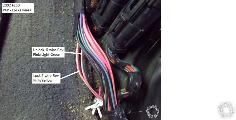
This is somewhat similar to the Pictorial on the 2002- 2005 F250. Here is a link :
https://www.the12volt.com/installbay/forum_posts.asp?tid=133810
Here is a photo from that Pictorial of the lock wires in the PKP ( your truck might be similar ) :
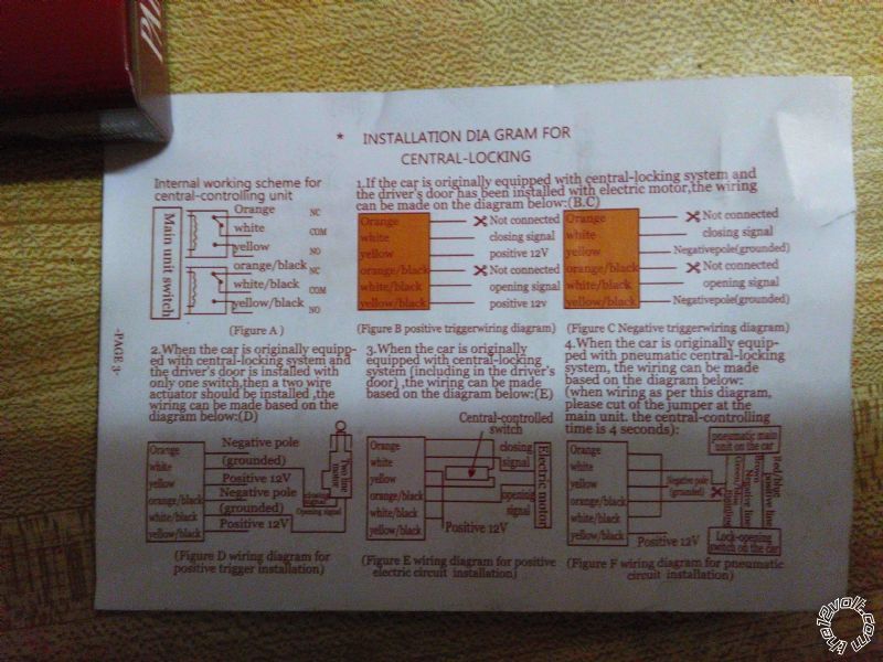
You will wire it it in the 5 wire Reverse mode using the two wires in the PKP. Here is the wiring for your after-market
unit :
Lock portion :
Orange wire ( aka Pin 87a ) to switch side of cut Pink / YELLOW wire in PKP
White wire ( aka Pin 30 ) to motor side of cut Pink / YELLOW wire in PKP
Yellow wire ( aka Pin 87 ) to +12V constant through 15 Amp fuse ( combine with Yellow/Black wire )
Unlock portion :
ORANGE / Black wire ( aka Pin 87a ) to switch side of cut Pink/Lt. Green wire in PKP
WHITE/ Black wire ( aka Pin 30 ) to motor side of cut Pink/Lt. Green in PKP
Yellow/Black wire ( aka Pin 87 ) to +12V constant through 15 Amp fuse ( combine with Yellow wire )
To determine which side of the cut wire is the switch side, connect a DMM to one side of the cut wire and press the drivers
door lock ( or unlock ) button. If the DMM goes to +12V you have the switch side.
-------------
Soldering is fun!