New member, new keyless and first
Printed From: the12volt.com
Forum Name: Car Security and Convenience
Forum Discription: Car Alarms, Keyless Entries, Remote Starters, Immobilizer Bypasses, Sensors, Door Locks, Window Modules, Heated Mirrors, Heated Seats, etc.
URL: https://www.the12volt.com/installbay/forum_posts.asp?tid=141554
Printed Date: May 16, 2026 at 2:56 PM
Topic: New member, new keyless and first
Posted By: thorvald
Subject: New member, new keyless and first
Date Posted: July 28, 2016 at 5:35 PM
I installed my first keyless and alarm this week without any problems, but I still think I must make some changes. I live in Norway and the cars produced for Norway has a different light setup then most of the world. The wire that was connected to the parking light are not the same as in the USA. I would like my direction lights to flash when I lock and unlock the car. But in Norway parking lights are wired to be two 5watt bulbs inside the headlamps. Therefor my question is, can I move the wire from the keyless/alarm over to the hazard button? That's the only way to make all the direction lights blink at the same time I think.
Thanks for this great forum 🙂
Replies:
Posted By: thorvald
Date Posted: July 28, 2016 at 5:37 PM
My car/Suv is a Mitsubishi Pajero/Montero sport 2000, European setup
Posted By: lurch228
Date Posted: July 28, 2016 at 7:44 PM
Need more info on system type and how it's wired now?
For the mean time if you were to go that route, you would want to connect to the wire out side of the flasher and would need to use a relay. To avoid any issues with the flasher trying to flash the lights, especially when remote started and having light output set to constant. If you get feed back issues then you would need to cut the out side wire and wire it to 87a, 30 to light side of cut wire,87and 86 to +12v constant, 85 to - parking light output. This applies if it is a positive feed flasher and you will need to verify this fact.
Posted By: thorvald
Date Posted: July 29, 2016 at 2:28 PM
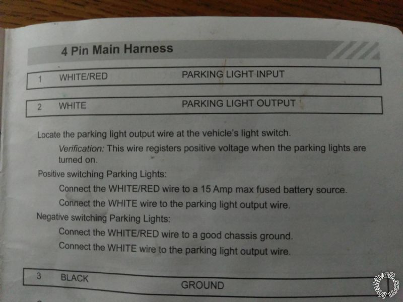
The Keyless/Alarm is a Code Alarm CA6554
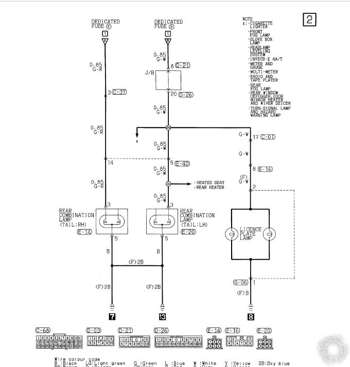
This is the wiring information for the parking lights
The first alternative is the one for my Mitsubishi
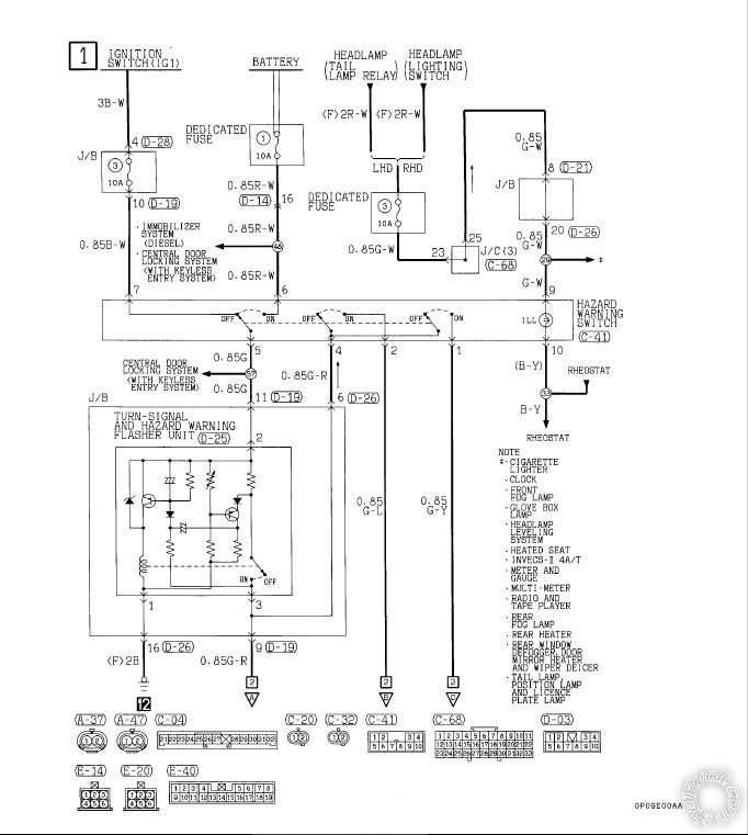
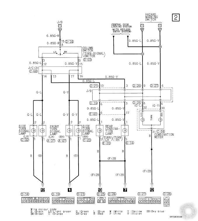
This is the wiring diagram for the Hazard and turn signal
This is about all i have for information on this :)
Posted By: lurch228
Date Posted: July 29, 2016 at 6:27 PM
Looks like you would need to connect after the hazard switch in diagram 1. Using 5 amp diodes band towards the vehicle wiring to connections 1 and 2 with (+) 12v or use 2 relays to power each circuit separate. The left and right are only combined when the hazard switch is on. So you will need to power them both.
Are you going to have the remote start set to run the lights constant or flashing?
Posted By: howie ll
Date Posted: July 30, 2016 at 1:08 AM
Not Norway, everywhere but North America uses amber direction indicators Lurch is correct.
As for the rest, find the GREEN/ blue and GREEN/ YELLOW in the steering column loom wire the Code as POSITIVE switching parking lights and split the white output via 2 X 1N5404 diodes, bands away from Code.
You can also add Shogun to the names in your first post.
-------------
Amateurs assume, don't test and have problems; pros test first. I am not a free install service.
Read the installation manual, do a search here or online for your vehicle wiring before posting.
Posted By: lurch228
Date Posted: July 30, 2016 at 10:33 AM
@howie ll Am I missing something or was there a post that has since been deleted? Just curious what I missed if so.
Posted By: howie ll
Date Posted: July 30, 2016 at 10:44 AM
Don't think so, I was just a bit astonished at the original post, Euro cars always had this set-up, it's alarm 101 on Euro cars, the truth is in Europe apart from the Romanian Company Falcon Electronics, part owned by DEI, no one in Europe can do alarms AND remote starts bar a few Brits (about 5 of us).
-------------
Amateurs assume, don't test and have problems; pros test first. I am not a free install service.
Read the installation manual, do a search here or online for your vehicle wiring before posting.
Posted By: lurch228
Date Posted: July 30, 2016 at 12:00 PM
Ok thanks
Posted By: thorvald
Date Posted: July 30, 2016 at 6:18 PM
So you guys can see what I write about I made I little clip.
First you see the lock/unlock blink from the 5 watt bulbs, here in Norway refereed to as parking lights. My Bosch extra lights also has parking lights. Then I go left to right with the direction lights and in the end hit the hazard button.
https://youtu.be/e9lSt3PuZfA
Posted By: lurch228
Date Posted: July 30, 2016 at 7:38 PM
You will need to follow what I posted above using either 5A diodes or relays and I prefer the constant light output for remote start indication, lights will still flash when locking or unlocking. Flashing the Bosch lights is not good for there longevity either. Using diodes is less wiring and parts as the unit can handle up 15A positive output. The way you have it now you are risking frying the light control in the Code Alarm powering all those lights.
Posted By: thorvald
Date Posted: July 31, 2016 at 7:32 AM
Thank you so much for the help. Then I have ordered some diodes.
I hope I can ask you one more question.
I thought all was good, but it might have done some damages wired the way it was. All of a sudden the Montero Sport are missing one rear left tail light. The right one is still there. The strange thing is that there is 12 volt to the lamp socket, but when I insert a bulb, the 12 signal drops out. It comes back when I remove the bulb.
I have no disconnected the Code Alarm waiting for the diodes, so thats not the problem at this point.
What could cause this?
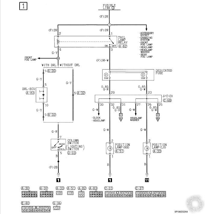
Wiring diagram:
Posted By: lurch228
Date Posted: July 31, 2016 at 7:57 AM
Sounds like blown dedicated fuse #3 10 Amp. Grounds are tied after tail, so with no bulb you can registrar 12v from right hand tail to chassis ground. Putting bulb re connects everything connected between right ground and fuse if blown. If fuse is good. One other thing is to make sure bulb filament isn't broken and shorted to the other inside the bulb, since it is a combination lamp/tail.
Posted By: thorvald
Date Posted: July 31, 2016 at 8:33 AM
Fuse is not blown. Tried 3 different bulbs, also the one bulb proven OK at the right side. Right comb lamp functions as it should.
As soon as I connect the bulb, it looses 12v.
Could I have fried some wires the way it was wired, making a short when I insert a bulb?
Posted By: thorvald
Date Posted: July 31, 2016 at 8:46 AM
Licence plate lamp tied onto the same wire, functions as it should
Posted By: lurch228
Date Posted: July 31, 2016 at 9:17 AM
With bulb out and lights off check plug for continuity to ground. Then turn lights back on and test other connectors that weren't for +12v to chassis ground.
Posted By: thorvald
Date Posted: July 31, 2016 at 9:50 AM
At the known good side there are continuity between brake and ground, also between taillight and ground. At the left problem side there are only continuity between ground and one of the circuits.
Posted By: thorvald
Date Posted: July 31, 2016 at 9:52 AM
This with lights off
Posted By: thorvald
Date Posted: July 31, 2016 at 10:39 AM
Did some more checking and it is the left problem side taillight that has no continuity when power off. Brake light has continuity power off. Right side has continuity on both circuit continuity.
Posted By: thorvald
Date Posted: July 31, 2016 at 4:27 PM
Spent most of the day trying to fix this but at this point I'm stuck
Posted By: lurch228
Date Posted: July 31, 2016 at 8:45 PM
No continuity on any of the left connectors when power off likely no ground, trace Black ground wire looking for a break or a bad ground to chassis.
Posted By: thorvald
Date Posted: August 01, 2016 at 1:34 AM
Not all, only the tail light part of the combination lamp socket. Rest is as it should be. Does this mean that there are a brake in the positive lead on that circuit? It can be a relay, it can't be the fuse and so on as they all share those.
Posted By: lurch228
Date Posted: August 01, 2016 at 3:21 AM
Start at the point of the wiring that works ie the point where the license plate wire splits since it works and work your way to the tail light until you find the break. Could be at plug or a wire fastening point if the wires were ever pulled to hard when changing the bulb prior. Wires do break right next to the plug as its a fixed flex point.
Posted By: thorvald
Date Posted: August 01, 2016 at 11:17 AM
Thank you so much for all the help! You guys are fantastic! 😇😇😇
I will revisit this problem closer to the weekend when time allows it 🙄
Posted By: lurch228
Date Posted: August 02, 2016 at 1:26 AM
Your welcome.
Posted By: racerjames76
Date Posted: August 04, 2016 at 11:52 AM
Hopefully I don't add more confusion here than I solve, but I did not see this mentioned. When you say 12v is present at the light socket are you testing with a DVOM or a test light? In this specific case I think a DVOM may not give you the whole story.
A test light must be connected across the terminals of the socket in order to test both current flow and strength of the ground.
If the test light does not light, remove the test light ground from the socket and place it on a chassis ground to see if a known good ground fixes the issue. If the light is dim then you either have a bad body ground at the (presumably) battery or a partial break in power. Partially blown fuse (don't just do a visual inspection, use a test light to load the circuit), or corroded wire/terminal.
We always harp about using a DVOM but in a known, non-computer related circuit where amperage flow is important you need to be able to load test both the power supply and the ground circuits.
Other important notes here do NOT stuff your test light into the socket! You can damage the socket and it will never work right again. Just simply place the leads gently on the surface of the metal contacts.
You can also test at the wire side as well using a t-pin by back probing it into the back side of the connector, or poke a small hole in the insulation of the wire, but remember to seal that hole up with some kind of silicone or liquid electrical tape to prevent corrosion. ------------- To master and control electricity is perfection. *evil laugh*
Posted By: thorvald
Date Posted: August 06, 2016 at 2:57 PM
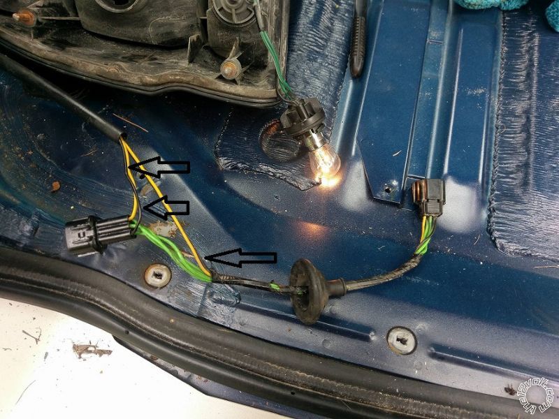
Then the problem is fixed. That little wiring harness in the picture was to blame. It is a aftermarket splitter for the trailer connector.
The black wire that I have highlighted with arrows in the picture splits the G-W wire, runs down to the trailer connector and back to the rear combination lamp. This wire was broken inside the trailer connector.
Posted By: lurch228
Date Posted: August 06, 2016 at 6:03 PM
Good to hear it's fixed.
|