RS and alarm install, 05 Chevy Express 3500
Printed From: the12volt.com
Forum Name: Car Security and Convenience
Forum Discription: Car Alarms, Keyless Entries, Remote Starters, Immobilizer Bypasses, Sensors, Door Locks, Window Modules, Heated Mirrors, Heated Seats, etc.
URL: https://www.the12volt.com/installbay/forum_posts.asp?tid=141699
Printed Date: March 26, 2026 at 8:25 AM
Topic: RS and alarm install, 05 Chevy Express 3500
Posted By: prince504
Subject: RS and alarm install, 05 Chevy Express 3500
Date Posted: September 09, 2016 at 6:30 PM
Looking to install a 2-Way remote start and alarm on a 2005 Chevy Express 3500. Would like to confirm if this vehicle has an immobilizer... Also, would also appreciate the wiring diagram for her as well. Looking into the iDatalink bypass with a Prestige APS-997E
Thnx in advance.
Replies:
Posted By: lurch228
Date Posted: September 10, 2016 at 6:35 PM
Should be the same as all other Express Vans series,
But you still need to verify the wires as with any install!
Wiring link: https://www.the12volt.com/installbay/forum_posts.asp?tid=46623
Passlock2 is standard equipment on all Gm vehicles of this year.
You only need a basic bypass for the Passlock2 if you are going to hardwire everything else. Otherwise if you want less wires to hook up you can do a iDatatlink bypass /convenience combo that can do locks/tach thru data also.
I like the xpresskit for GM vehicles. If you use the DBALL/2 you get 35 supported functions thru DATA. With just 1 wire to the vehicle. Then that leaves Foot brake, Parking lights, Side door, rear doors and 6 Remote start connections to ignition switch, and Constant +12v battery Power(Direct to battery for alarm) and ground.
DBALL/2 Functions in D2D mode.
CC-Heated Mirrors
CC-Heated Seats Activation
CC-Power Mirror Memory
CC-Power Seat Memory
CC-Radio Channel Memory
CC-Rear Window Defogger Activation
DL-Arm Factory Security
DL-Disarm Factory Security
DL-Door Lock Control
DL-Door Unlock
DL-Driver Priority Unlock
FOB-Control of aftermarket alarm with OEM remote
PK-Immobilizer Bypass-Data No Key Req'd
RS-RAP Shut Down (Retained ACC Power)
RS-Tach / RPM Output
SS-Entry Monitoring Driver Door Pin
SS-Entry Monitoring Front Door Pins
SS-Factory Alarm Trigger Monitoring
ST-Ignition Status
ST-Keysense Status
Posted By: prince504
Date Posted: September 11, 2016 at 9:12 AM
lurch228 wrote:
Should be the same as all other Express Vans series,
But you still need to verify the wires as with any install!
Wiring link: https://www.the12volt.com/installbay/forum_posts.asp?tid=46623
Passlock2 is standard equipment on all Gm vehicles of this year.
You only need a basic bypass for the Passlock2 if you are going to hardwire everything else. Otherwise if you want less wires to hook up you can do a iDatatlink bypass /convenience combo that can do locks/tach thru data also.
I like the xpresskit for GM vehicles. If you use the DBALL/2 you get 35 supported functions thru DATA. With just 1 wire to the vehicle. Then that leaves Foot brake, Parking lights, Side door, rear doors and 6 Remote start connections to ignition switch, and Constant +12v battery Power(Direct to battery for alarm) and ground.
Thanks! I did the install yesterday using an iDatalink & Compustar CS6502-AS via W2W and ran into some hiccup. The remote start works fine but the door trigger gave me some issues.
I understood that the door triggers would need to be isolated. I first found the wires at the BCM and test the Front Driver Door --> TAN (-) in PIN B4, the PASSENGER door and REAR Cargo door --> LT. GREEN (-) in PIN A5, and the REAR Door --> YELLOW/BLACK (-) in PIN A10 and confirmed them with my multimeter with the black probe connected to (-) and the red probe tapping the wires. Each wire showed 12V at rest and .674V DC when I opened the door.
So following Tec Doc 1076 as a guide, I cut each wire and soldered a 1A diode with band facing away from the BCM and then soldered a diode from each wire (after the band side) going to the door trigger of the alarm. I initially twisted the ends of diodes going from the each BCM wire to the alarm door trigger but noticed my multimeter showed 4V DC at with all doors closed when measuring the alarm door trigger wire.
So I proceeded to wire each diode from the BCM wires individually to the alarm door trigger wire and for some odd reason, only the REAR right door triggers the alarm. The Driver, Passenger and Cargo Door don't trigger the alarm.
Using my multimeter, I noticed that if I measure btw the BCM the the inline diode on the cut BCM wires, the multimeter reads 12V with the doors closed and .674V DC with them opened but when I measure after the band side of the diode side, I get no readings (something like 10.5 mV) regardless of if the doors are opened or closed.
Any ideas? Should I get a DBALL since it gets the door status via data and the iDatalink doesn't? I have never used the DBALL before and thought you had to be a dealer to be able to get them flashed.
Thnx
Posted By: lurch228
Date Posted: September 11, 2016 at 2:01 PM
You didn't need to cut the vehicle trigger wires. Only diode them from each other to the alarm.
Unless the Body Control Module is shutting down causing false triggers on the door and rear hatch/trunk inputs. This is more common on Ford's.
Posted By: prince504
Date Posted: September 13, 2016 at 12:54 AM
lurch228 wrote:
You didn't need to cut the vehicle trigger wires. Only diode them from each other to the alarm.
Unless the Body Control Module is shutting down causing false triggers on the door and rear hatch/trunk inputs. This is more common on Ford's.
Oh wow. Guess I did more than was necessary. Will have to redo the wiring. Also @lurch288, would it be okay to use the dome light supervision wire as a trigger as well? Have you ever done this? That way, if any of the door were to be opened, the alarm would go off...
Regards
Posted By: lurch228
Date Posted: September 13, 2016 at 1:46 AM
Yes the dome can be used just be aware if the dome light stays on after closing the door and arming the alarm it will notify with a secondary chirp if you don't wait for the dome-light to go off before arming.
Posted By: prince504
Date Posted: September 13, 2016 at 3:52 AM
lurch228 wrote:
Yes the dome can be used just be aware if the dome light stays on after closing the door and arming the alarm it will notify with a secondary chirp if you don't wait for the dome-light to go off before arming.
I noticed in the settings of the alarm there is a dome light delay option to delay the door trigger arming to either 5 secs, 45 secs or Auto. Will probably have to use one of those.
Thnx
Posted By: lurch228
Date Posted: September 13, 2016 at 4:01 AM
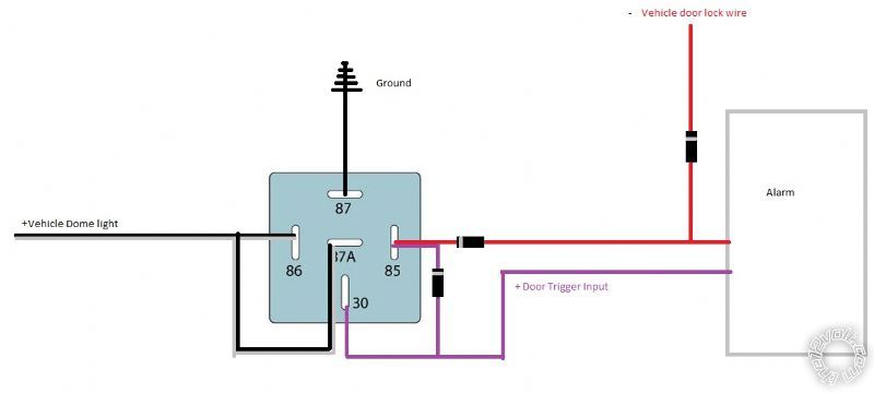
Using a relay to isolate will over ride the + trigger until dome goes off.
Connect 87 to ground, + trigger alarm input to 30 and 85 along with the negative lock output from alarm(using diodes as shown), Dome to 87a and 86.
With dome on and you arm the alarm it locks the doors with a - trigger connecting 87 to 30 and 85 maintaining the relay connection and sending negative to the positive trigger input of alarm. When domelight shuts off relay de-energizes connecting dome 87a to 30 alarm + input trigger. If domelight is off and you arm the alarm the relay can't activate due to no +12v. Now when door is opened it can trigger the + input trigger since relay is not active.
From memory this should do what you need if you want to eliminate the secondary chirp due to dome light being on when arming.
Posted By: lurch228
Date Posted: September 13, 2016 at 4:06 AM
I mainly install DEI products but if the Prestige has the option to delay the the Door trigger arming then that is another option you can use.
Posted By: prince504
Date Posted: September 13, 2016 at 11:14 AM
lurch228 wrote:
Using a relay to isolate will over ride the + trigger until dome goes off.
Connect 87 to ground, + trigger alarm input to 30 and 85 along with the negative lock output from alarm(using diodes as shown), Dome to 87a and 86.
With dome on and you arm the alarm it locks the doors with a - trigger connecting 87 to 30 and 85 maintaining the relay connection and sending negative to the positive trigger input of alarm. When domelight shuts off relay de-energizes connecting dome 87a to 30 alarm + input trigger. If domelight is off and you arm the alarm the relay can't activate due to no +12v. Now when door is opened it can trigger the + input trigger since relay is not active.
From memory this should do what you need if you want to eliminate the secondary chirp due to dome light being on when arming.
Although the alarm system has a dome light delay function , I still wish to understand the relay setup you described and had a few questions...
- are the diodes on the (-) alarm door lock wire backwards? With their current orientation, a (-) signal wouldn't be able to pass through
- also how is the relay connection maintained if the door lock pulse is is for a split sec? The connection btw pin 87 & 30 would last barely 1 sec. I thought lock/unlock pulse from alarms weren't latched.
- why have the + door trigger connected to pin 85 at all if a (-) ground signal is sent to the +door trigger once the relay is activated anyway...
Posted By: lurch228
Date Posted: September 13, 2016 at 12:43 PM
Alarm outputs that are negative are open until the alarm connects them to ground acting as the path to ground (Alarm is a switched ground). The door lock diode is there to block the Ground from the door lock from getting back to the relay when the locks are activated from the manual power door lock or factory keyless.
As long as the dome is on relay coil has positive and the door lock output momentarily closes the relay connecting the ground 87 to 30 and feeds 85 maintaining the latch until the 12v goes away.
It's the connection that feeds the second constant ground from 30 to 85. As 87 is a NO (Normally Open) no connection until coil is energized. And door lock output initializes the connection. Grounding a + input has no potential so its the same as being open.
Posted By: prince504
Date Posted: September 13, 2016 at 8:03 PM
lurch228 wrote:
Alarm outputs that are negative are open until the alarm connects them to ground acting as the path to ground (Alarm is a switched ground). The door lock diode is there to block the Ground from the door lock from getting back to the relay when the locks are activated from the manual power door lock or factory keyless.
As long as the dome is on relay coil has positive and the door lock output momentarily closes the relay connecting the ground 87 to 30 and feeds 85 maintaining the latch until the 12v goes away.
It's the connection that feeds the second constant ground from 30 to 85. As 87 is a NO (Normally Open) no connection until coil is energized. And door lock output initializes the connection. Grounding a + input has no potential so its the same as being open.
Ok I think I get it now. But please look at the orientation of the diodes on the door lock wire. The anode is facing the alarm which means that the alarm would not be able to send a ground to pin 85 of the relay.
Also, how long after initiating the door lock pulse on the alarm remote does the relay stay energized?
Posted By: lurch228
Date Posted: September 13, 2016 at 11:56 PM
Sorry about the diodes was tired and they are all backwards.
The relay can only stay on until the dome turns off once energized by the door lock (-) output.
Here's the corrected Diagram.
Posted By: prince504
Date Posted: September 14, 2016 at 7:22 AM
lurch228 wrote:
Sorry about the diodes was tired and they are all backwards.
The relay can only stay on until the dome turns off once energized by the door lock (-) output.
Here's the corrected Diagram.
The diode orientation on the + door trigger input wire was initially correct. But I get the point.
Also, since you are familiar with DEI products, can any1 create an account to gain the ability to flash their bypass modules?
Posted By: lurch228
Date Posted: September 14, 2016 at 1:27 PM
Last time I flashed you can do basic flashing with out a account but to do the advance flashing like RSR, RXT, and 3x lock start you needed to be a authorized dealer or installer to do those. haven't done any flashing since they merged xpresskit.com into directechs.com so you will need to register here:. https://www.directechs.com/Register.aspx
If your email address has been added to the DirectedDealers.com system as a installer for an authorized Directed dealer or distributor then you will also have access to the directwire as well, otherwise you can only flash module's and access forums.
Posted By: lurch228
Date Posted: September 14, 2016 at 2:06 PM
Directwire
2005 Chevrolet Express Van - North America
Remote Start, Security, Keyless Entry, Accessories
Item Wire Color Polarity Wire Location
12 Volts RED / black (40A) + ignition harness
Second 12 Volts RED / black (40A) + ignition harness
Starter yellow + ignition harness
Ignition pink + ignition harness
Second Ignition white + ignition harness
Accessory orange + ignition harness
Second Accessory brown + ignition harness
Keysense lt. green - ignition harness
Data Bus yellow (resistor code), tan (ground) Passlock 2 Passlock sensor on ignition key cylinder
CAN Bus SW purple (J1850 Class 2 Serial Data) data data link connector, black 16 pin plug, pin 2
Power Lock lt. blue - driver kick or BCM, lt. blue plug, pin B5
Power Unlock white (all doors); lt. green (driver door only) - driver kick or BCM, lt. blue plug, pin B10; gray plug, pin A7
Lock Motor gray 5 wire driver kick, door harness
Driver Unlock Motor tan 5 wire driver kick, door harness
Passenger Unlock Motor tan 5 wire fuse box under driver seat, white 68 pin plug, pin A10
Parking Lights (+) brown + fuse box under driver seat, black 68 pin plug, pin E1
Parking Lights (-) BROWN / white - headlight switch or BCM, brown plug, pin B2
Hazards white - hazard switch or BCM, gray plug, pin A5
Turn Signal (Left) lt. blue/white + turn signal switch
Turn Signal (Right) dk. blue/white + turn signal switch
Headlight white - headlight switch or BCM, lt. blue plug, pin A12
Reverse Light lt. green + BCM, black plug, pin F
Left Front Door Trigger tan - driver kick or BCM, lt. blue plug, pin B4
Right Front Door Trigger lt. green - BCM, lt. blue plug, pin A5
Left Rear Door Trigger yellow/black - BCM, lt. blue plug, pin A10
Right Rear Door Trigger same as left rear door trigger
Dome Light gray/black or dk. blue/white + BCM, black plug, pin E
Trunk/Hatch Pin same as right front door trigger
Trunk/Hatch Release lt. blue (unlock rear cargo door only) - BCM, gray plug, pin A8
Power Sliding Door (Left) lt. blue (F), lt. grn (R) (left side access panel) - BCM, purple plug, pins B8 and B7
Power Sliding Door (Right) lt. blue (right side access panel) - BCM, purple plug, pin A7
Tachometer white (4.3L), purple (4.8L, 5.3L, and 6.0L) ac PCM on driver fender, green plug, pin 26
Fuel Pump gray + underhood fuse box, white 32 pin plug, pin C5
Rear Defroster white + latched fuse box under driver seat, black 68 pin plug, pin B12
Mirror Defroster same as rear defroster
Speed Sense dk. GREEN / WHITE or yellow/black ac PCM on driver fender, green plug, pin 50 or 49
Brake Wire white + brake switch
Parking Brake lt. blue - parking brake switch or BCM, lt. blue plug, pin A7
Horn Trigger tan - horn switch or BCM, gray plug, pin B9
Wipers pink (L), dk. blue (H), gray (input) +,- wiper switch
Left Front Window (Up/Down) dk. blue - brown A driver window switch
Right Front Window (Up/Down) white - orange A driver kick, door harness
|