08 Nissan Titan RS - 6200S - Blade-AL
Printed From: the12volt.com
Forum Name: Car Security and Convenience
Forum Discription: Car Alarms, Keyless Entries, Remote Starters, Immobilizer Bypasses, Sensors, Door Locks, Window Modules, Heated Mirrors, Heated Seats, etc.
URL: https://www.the12volt.com/installbay/forum_posts.asp?tid=142060
Printed Date: April 04, 2026 at 7:07 AM
Topic: 08 Nissan Titan RS - 6200S - Blade-AL
Posted By: tbird2340
Subject: 08 Nissan Titan RS - 6200S - Blade-AL
Date Posted: November 19, 2016 at 2:47 PM
I've been out the remote start game for years.. Want to put one in my new (used) 08 Titan..
I have a Compustar 6200S brain in my stock from when I used to do this on the side..
I also have an XK02 bypass which looks like will work.. I had planned on getting RF-2WG9-SP remote/antenna..
I'm also wondering if getting a Blade-AL would make the install easier rather then the XK02?
I did see the wiring posted here but it was from 2008 and the pictures were dead.. I didn't know if someone could post it and if they had any tips/pictures/advise as well..
Thanks so much!
Replies:
Posted By: loganemakf
Date Posted: November 20, 2016 at 5:57 PM
idatalink's products are incredibly easy to wire and program (their guides are excellent, key learn procedure is super simple for most vehicles). I don't know anything about the bypass you mentioned (Compustar is all I install, and idatalink most of the time), but between the ease of use and clean install you get from a blade cartridge, I'd go with them.
With that said, idatalink isn't as friendly to hobbyists and diy guys like us as some other companies. You need their flash cable (and to sign up for an account on their "dealer only" website) or pay someone on ebay to flash for you. Better to get the cable in my opinion; $35 and you can use it to change options later (on the bypass AND Compustar controller).
Either way, I'd also recommend looking into using a T-harness as well. Fortin sells one for your truck (THAR-NIS2; ~$40 on ebay) intended for their Evo-One remote start/bypass all-in-one unit. I just did a 2014 Tundra with one of them; just cut off the end intended for their controller and solder on the pigtail that goes to the 6200. Of course, you'll want to double check the wiring (sometimes Fortin's solutions are a bit weird; check their wiring against a wiring diagram online) and the bench prep will be a bit more work but it'll save you a bunch of time in the vehicle.
Oh, and the G9's are great remotes especially in terms of bang-for-the-buck. Like $80 right now; a steal for a 3000 ft. 2-way if you ask me (last year it wasn't uncommon for that kit to sell for $90-110).
Posted By: tbird2340
Date Posted: November 21, 2016 at 10:17 AM
Thanks much for the reply..
So what exactly to those T-Harness's do? What's the benefit?
Posted By: tbird2340
Date Posted: November 21, 2016 at 10:55 AM
Also, so how do I know which type of install to follow for my Titan? Is it type 1? It says standard key is type 1 and standard key with alarm is type 2.. How do I know if I have the alarm?
This is the manual for the ADS-AL that I need, I believe.. It looks like I only need to connect 7 total wires? Is that right?
Posted By: loganemakf
Date Posted: November 21, 2016 at 12:01 PM
A pretty standard way to test for an alarm would be to roll the window down, close all the doors, lock the truck, wait about a minute, then reach through the window and unlock & open the door. Another way you might be able to test for it is by locking the truck (again, drivers window open), waiting about a minute, then reaching in and popping the hood (since the idatalink guide indicates that the alarmed models have a hood pin).
While the link to the idatalink guide in your post doesn't work (looks like it's missing a couple parentheses for some reason), it appears to be the right one (NI4). And yes, 7 wires for the bypass.
As far as the T-harness goes, it eliminates the need for you to splice into the vehicles main ignition wires (ACC/IGN/START/etc.) by providing factory-like connectors. The T-harness has a pigtail pre-spliced with a connector for the remote start brain on the end. This way, when you go to install, you:
1. Unplug the ignition connector from it's socket (probably on or near the steering column)
2. Plug the male ignition connector on the T-harness into the socket in the vehicle
3. Plug the vehicle's ignition connector (disconnected in step 1) to the female ignition socket on the T-harness.
4. Plug the controller-specific end into the remote start controller (in this case, it's Fortin-specific)
The only work you would have to do in this case happens out of the vehicle. Cross reference the wire colors in the vehicle to their corresponding colors on the new harness, then use that information to neatly solder on the Compustar main harness in place of the Fortin one.
For example (these colors are just made up):
+12V - Red (in vehicle) -> Red (T-harness) -> Red + RED / White (Compustar harness)
ACC1 - White (in vehicle) -> Orange (T-harness) -> White (Compustar harness)
ACC2 - Brown (in vehicle) -> Pink (T-harness) -> Blue (Compustar harness)
IGN - Pink (in vehicle) -> Green (T-harness) -> Green (Compustar harness)
... etc.
Posted By: tbird2340
Date Posted: November 21, 2016 at 1:56 PM
Thanks again for the reply.. So if I test for the alarm the way you suggested and the horn goes off.. That means per Idatalink's manual I would have "STD key w/ alarm" ? Therefore I'd go with type 2 of install?
Also, alarm is different then immobilizer.. Do you know how to tell if I have immobilizer or not?
As far as the T-harness.. Those look badass but since this is a truck and I have plenty of room to get access to those wires I'm going to save the money..
Still trying to figure out the wiring.. Man, I did about 30 installs 10 years ago.. Crazy how the mind forgets things! LOL
Posted By: loganemakf
Date Posted: November 21, 2016 at 3:55 PM
No problem.
Yes, alarm in the truck = install type 2. You should know that a type 2 install will probably be more difficult due to the fact that door locks aren't controlled through the vehicle computer. On the type 2 wire cross reference chart, notice how it says "Empty" in the wire color column for lock/arm and unlock/disarm? Nissan doesn't have a wire in those pin locations so your options for interfacing with the locks are either a) sticking new wires in the plug and bending them over, hoping not to short them out (pretty sketchy) or b) finding a different place to tap into the power locks. It varies by vehicle (obviously), but I did an '04 maxima and had to snake wires through the driver door boot to get to some actual lock wires. Huge PITA when the rubber boot is a skinny S shape.
The T-harness is essentially a direct trade: money for time. So long as you make good connections, don't intend to remove the system and have plenty of time for the install, there's no need for it.
And yes, it's somewhat like math: if you don't use it regularly, you lose (some of) it!
Posted By: tbird2340
Date Posted: November 21, 2016 at 3:57 PM
Oh man.. So if I have the transponder there's no bypass that can do the locks? That sucks!!
How do I tell if I have transponder again?
Posted By: loganemakf
Date Posted: November 21, 2016 at 4:12 PM
Ah, sorry about that; went and found a video about testing for immobilizer but then didn't paste in the link. Here you go: https://www.youtube.com/watch?v=aFU5ix20uDI
(I'd probably recommend being a bit more liberal on your use of aluminum foil than the guy in the video, though, just to be sure)
And no, if you have an alarm you're in for a fun time with the locks. Either way, you probably have a transponder/immobilizer (but might not) which just determines what you do with the ORANGE / black wire to the Blade.
Posted By: tbird2340
Date Posted: November 22, 2016 at 11:19 AM
OK. So if I have the alarm, the Blade-AL will not do the locks.. It looks like if I do have the alarm the Blade-AL also doesn't arm/disarm the alarm either?
Posted By: tbird2340
Date Posted: November 22, 2016 at 2:16 PM
OK.. If you have time to review this it would be much appreciated.. If you have a membership to one of the pay wiring sites that you could provide wiring that would be appreciated as well.. Got some conflicting stuff from my googling but will test every wire..
Connector 1 (CN1), 6-Pin
Pin 1 White Accessory 12V positive (+) output. Connect to Red at Ignition Switch Harness
Pin 2 Yellow - Starter 12V positive (+) output. - Connect to Blue/Green at Ignition Switch Harness
Pin 3 Green Ignition 12V positive (+) output and input. - Connect to BLACK/ Red at Ignition Switch Harness
Pin 4 Black - Ground negative (-) input. Connect to Ground
Pin 5 Red - Constant 12V positive (+) power input. - Connect to Green at Ignition Switch Harness
Pin 6 GREEN / WHITE Parking light positive (+) - Connect to RED / Blue at Dimmer Switch on Dash
Connector 3 (CN2), 20-Pin: Programmable Output Connector (POC)
Pin 1 Blue - 250mA negative (-) output when armed and during remote start (while running). N/A
Pin 2 ORANGE / Black - Parking Light Reminder (-) input that monitors the vehicles parking lights. N/A
Pin 3 GREEN / WHITE [POC 1] - Parking light 250mA negative (-) output. - N/A
Pin 4 Light Blue Parking / Emergency brake negative (-) input. N/A
Pin 5 RED / Black [POC 2] 2nd Starter 250mA negative (-) output. This output can be used to trigger the prewired relay located on the main ignition harness. Needed? I believe so..
Pin 6 Light Blue/White - Brake 12V positive (+) input. - RED / Green At Switch Above the Brake Pedal
Pin 7 Green [POC 3] - 2nd Ignition 250mA negative (-) output. N/A
Pin 8 Violet/Black - Trunk negative (-) input. N/A
Pin 9 WHITE/ Black [POC 4] - 2nd Accessory 250mA negative (-) output. N/A
Pin 10 RED / White - Door trigger input. N/A
Pin 11 Black [POC 5] Status/Ground while running 250mA negative (-) output. - N/A
Pin 12 BROWN / White - This is a dual-purpose wire that is selectable through Option 4-9 N/A
Pin 13 Orange [POC 6] - Factory Arm 250mA negative (-) output. Needed? Does it arm with lock? Bypass controlling?
Pin 14 Pink - Slave/Closed Loop negative (-) input. N/A
Pin 15 ORANGE / White [POC 7] - Factory Disarm 250mA negative (-) output- Needed? Disarm when unlock? Bypass controlling?
Pin 16 Yellow/Black - Engine sensing input. N/A
Pin 17 White [POC 8] - Horn honk 250mA negative (-) output. - RED / White In Harness at Steering Column
Pin 18 Gray/Black Hood Pin negative (-) input. - N/A
Pin 19 Violet [POC 9] - Violet [POC 9] - Auxiliary 1 - 250mA negative (-) output. - N/A
Pin 20 Brown - Siren 12V positive (+) output. - N/A
Connector 5 (CN4), 6-Pin
Pin 1 Not used
Pin 2 Violet/White - Trunk release 250mA negative (-) output. - N/A
Pin 3 ORANGE / Black - 2nd Unlock 250mA negative (-) output. - N/A
Pin 4 Blue - Unlock 250mA negative (-) output. N/A Being controlled by bypass?
Pin 5 Blue/Black - Lock 250mA (-) negative output. - N/A Being controlled by bypass?
Pin 6 Not used
Blade-AL(DL) NI4 Firmware
Ignition Output - Connect to BLACK/ Red at Ignition Switch Harness
Unlock/Disarm Connect to Pink (-) in harness in driver kick panel ?
Lock/Arm Connect to Red (-) in harness in driver kick panel ?
WHITE/ Black Immobilizer Data Vehicle Side Connect to Brown Pin 4 on Immobilizer
WHITE/ Red Immobilizer Data Connector Side Connect to Brown Pin 4 on Immobilizer
BROWN / Red CANH Connect to Blue Pin 6 on OBDII
BROWN / Yellow CANL Connect to Pink pin 14 on OBDII
ORANGE / Black Immobilizer Data Connect to Brown Pin 4 on Immobilzer
Orange Immobilizer Clock Connect to Green Pin 2 of immobilizer
Gray/Red Ground Connect to Ground
Posted By: tbird2340
Date Posted: November 25, 2016 at 6:00 PM
Any chance to review this yet? The only part that I'm unsure about is the locks..
I purchased a wiring diagram for wire color and they say this about locks:
"Lock and arm at BCM pin 13 - empty spot"
"Unlock and disarm at BCM pin 14 - empty spot"
So what does that even mean?
Then bulldog's says:
POWER LOCK - BLUE (TYPE B), NOTE #3 - @ POWER WINDOW Main Switch, (WHITE, 16-PIN PLUG), PIN 6 or 4
POWER UNLOCK - RED (TYPE B), Requires Double Pulse, NOTE #4 @ POWER WINDOW Main Switch, (WHITE, 16-PIN PLUG), PIN 7 or 6
NOTE #3: TEST this wire while Turning the KEY in the Drivers Door. This wire will also ARM the
FACTORY ALARM.
NOTE #4: TEST this wire while Turning the KEY in the Drivers Door. This wire will also DISARM the
FACTORY ALARM.
Thanks
Posted By: kreg357
Date Posted: November 26, 2016 at 11:04 AM
Concerning the locks...
Nissans were typically a PITA because you had to run wires into the door. Then some really bright fellow found
out that the locks could be controlled from inside the vehicle by making the necessary connections at the BCM.
The goof was that depending on the vehicle and options, some times there were no actual wires at those pins.
The work-around was to use a properly oriented diode, inserted into the connectors empty pin hole and connect
the R/S aftermarket system locks wires to the corresponding diode. The diodes leg is the correct diameter to
fit and make good contact internally. Just have to secure the diode to an adjacent wire to prevent it from
moving out of the connector. Of course, another way is to obtain the correct size connector pins ( junk yard
pull ) and add them to the BCM connector, then solder on your R/S lock wires.
-------------
Soldering is fun!
Posted By: tbird2340
Date Posted: November 29, 2016 at 8:15 AM
I was going to use the lock wires at the switch instead of screwing with putting wires in the BCM.. I probed all the red and blue wires in that harness and could not find one that went to ground when pressing the lock/unlock on the door..
Any ideas? Thanks
Posted By: tbird2340
Date Posted: November 30, 2016 at 7:37 AM
Also, I did some wiring last night.. I do not have a dimmer switch so can't tap my parking lights there.. Any ideas on where to grab this?
Thanks
No idea why I don't have a dimmer switch.. I never realized it..
Posted By: tbird2340
Date Posted: December 01, 2016 at 7:31 AM
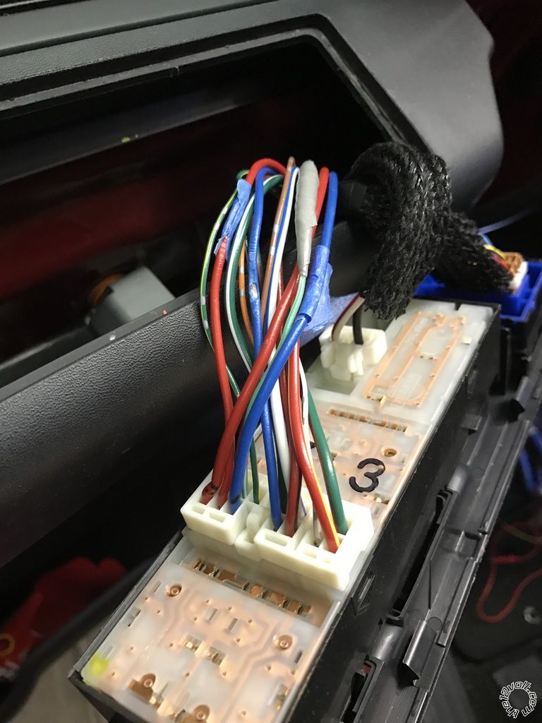
OK the trick was the wires for the locks need to be tested with the key in the door turning.. I did just run wires to the switch pictured above.. Major PITA..
Last question.. For the lock/arm unlock/disarm wires.. Do I connect them to my blade wires or the 6 pin connector of my remote start, or both?
Thanks
Posted By: tbird2340
Date Posted: December 01, 2016 at 9:48 PM
I just finished installing a Compustar CS6200 with a Blade-AL and RF-2WG9-SP remote/antenna in my 2008 Nissan Titan..
I'm trying to program the remotes.. (I programmed the blade already).
When I do the off/on cycle 5 times I get two parking light blinks instead of the one that the manual says I should.. I try programming a remote and it doesn't work..
Any ideas?
Also, my security light in my Titan is flashing with the key out.. I'm not sure if that's normal and I've just never noticed it or if that is an issue.. Truck does start normally..
Thanks for any help..
Posted By: tbird2340
Date Posted: December 02, 2016 at 7:29 AM
Thought of something driving in.. I didn't hook up the hood pin to anything so that very well may be it.. Will try that tonight..
Posted By: tbird2340
Date Posted: December 02, 2016 at 5:11 PM
OK someone please help.. The remote starter flashes the parking lights twice after going into remote programming and I don't know why.. Here is how I have everything hooked up:
Connector 1 (CN1), 6-Pin
Pin 1 White Accessory 12V positive (+) output. Connect to Red at Ignition Switch Harness
Pin 2 Yellow - Starter 12V positive (+) output. - Connect to Blue/Green at Ignition Switch Harness
Pin 3 Green Ignition 12V positive (+) output and input. - Connect to BLACK/ Red at Ignition Switch Harness
Pin 4 Black - Ground negative (-) input. Connect to Ground
Pin 5 Red - Constant 12V positive (+) power input. - Connect to Green at Ignition Switch Harness
Pin 6 GREEN / WHITE Parking light positive (+) - Connect to RED / Blue at Dimmer Switch on Dash
Connector 3 (CN2), 20-Pin: Programmable Output Connector (POC)
Pin 5 RED / Black [POC 2] 2nd Starter 250mA negative (-) output. This output can be used to trigger the prewired relay located on the main ignition harness. Connected to violet wire on relay for 2nd starter.
Pin 6 Light Blue/White - Brake 12V positive (+) input. - RED / Green At Switch Above the Brake Pedal
Pin 17 White [POC 8] - Horn honk 250mA negative (-) output. - RED / White In Harness at Steering Column
Pin 18 Gray/Black Hood Pin negative (-) input. - Connected to Ground
Connector 5 (CN4), 6-Pin
Pin 4 Blue - Unlock 250mA negative (-) output. Ran wire to RED wire at switch in door.
Pin 5 Blue/Black - Lock 250mA (-) negative output. - Ran wire to BLUE wire at switch in door.
Blade-AL(DL) NI4 Firmware
WHITE/ Black Immobilizer Data Vehicle Side Connect to Brown Pin 4 on Immobilizer
WHITE/ Red Immobilizer Data Connector Side Connect to Brown Pin 4 on Immobilizer
BROWN / Red CANH Connect to Blue Pin 6 on OBDII
BROWN / Yellow CANL Connect to Pink pin 14 on OBDII
ORANGE / Black Immobilizer Data Connect to Brown Pin 4 on Immobilzer
Orange Immobilizer Clock Connect to Green Pin 2 of immobilizer
Gray/Red Ground Connect to Ground
Any ideas why I can't get the remotes programmed?
Posted By: tbird2340
Date Posted: December 02, 2016 at 7:08 PM
Ok I'm an idiot. I was waiting too long and the two flashes were it exiting programming mode. Got them programmed. Learned the tach and got good verification for that..
Now when I try a remote start I get 6 flashes which says it's the hood pin.
I have the hood pin wire connected directly to ground (tested and verified) so why is it saying this?
Posted By: the12volt
Date Posted: December 02, 2016 at 7:16 PM
The hood pin wire should only show ground when the hood is open. The hood pin wire should not show ground when the hood is completely closed. If it is showing ground when you attempt to remote start it, it will not start and it will show that error. -------------  the12volt Support the12volt.com the12volt Support the12volt.com
Posted By: tbird2340
Date Posted: December 02, 2016 at 7:20 PM
All ID10.T errors!! Got it going!!
Posted By: loganemakf
Date Posted: December 02, 2016 at 7:36 PM
Looking quickly at this...
First, if you aren't installing a hood pin leave the hood pin wire disconnected. If the brain sees ground on the hood pin input, it thinks the hood is open. Hood closed = no connection on hood pin wire.
Second, for the Blade: you cut the immobilizer wire (the wire that the WHITE/ black and RED / black connects to), right?
Third, several posts up you mention the lock/arm unlock/disarm wires and connecting them to either the Blade harness or the controller's main harness... I have no idea what you're talking about with this.
Posted By: loganemakf
Date Posted: December 03, 2016 at 6:45 PM
Ignore my last post; was writing it while you got everything solved.
Glad everythings working for you now!
|