Toyota Supra Remote Start Viper 5706v
Printed From: the12volt.com
Forum Name: Car Security and Convenience
Forum Discription: Car Alarms, Keyless Entries, Remote Starters, Immobilizer Bypasses, Sensors, Door Locks, Window Modules, Heated Mirrors, Heated Seats, etc.
URL: https://www.the12volt.com/installbay/forum_posts.asp?tid=142245
Printed Date: May 15, 2026 at 7:30 PM
Topic: Toyota Supra Remote Start Viper 5706v
Posted By: golfer2000
Subject: Toyota Supra Remote Start Viper 5706v
Date Posted: December 16, 2016 at 8:14 PM
I've managed to find 95 percent of the wires for the install but the horn, disarm, and hood wires elude me. I found the blue red for the horn in the steering column but it's not the horn trigger. In fact I tried all the blue wires and non are it. I can't find the theft ECU in the passenger kick panel at all and there are several white wires in the driver kick panel for the disarm but no unlock. Can anyone help me out with location these three connections? Thanks!
Replies:
Posted By: golfer2000
Date Posted: December 16, 2016 at 8:15 PM
It's a 1994 non turbo auto toyota supra if it matters.
Posted By: golfer2000
Date Posted: December 18, 2016 at 2:08 AM
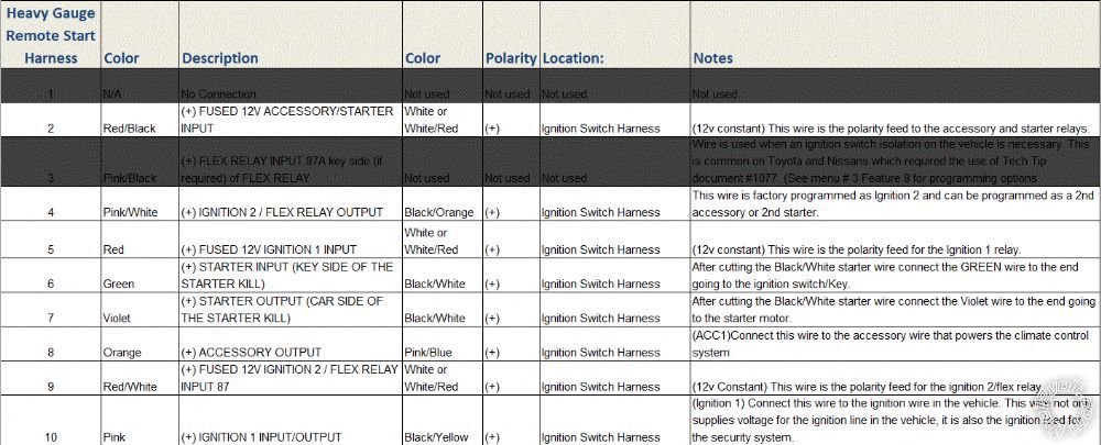
Also I believe I may have some wires wrong on my heavy gauge harness as I seem to have a large parasitic drain. Can anyone verify?
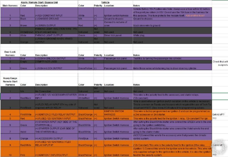
Per downloads chart:
Posted By: golfer2000
Date Posted: December 18, 2016 at 2:12 AM
My chart got compressed pretty bad when uploaded so if you cant read the text: https://drive.google.com/file/d/0By1NhbvLzu-9VFVHR01UNXRjcWc/view?usp=sharing
Posted By: golfer2000
Date Posted: December 19, 2016 at 11:10 AM
Anyone? My biggest concern is the heavy gauge harness if anyone can help with that.
Posted By: smokeman1
Date Posted: December 19, 2016 at 5:11 PM
From your Heavy Gauge Harness:
Red, RED / White, and RED / Black should all go to a 12 volt constant source. In your listing, White or WHITE/ Red.
-------------
When all else fails, Read the Instructions
Support the12volt.com Make a Donation
Posted By: golfer2000
Date Posted: December 19, 2016 at 5:33 PM
smokeman1 wrote:
From your Heavy Gauge Harness:
Red, RED / White, and RED / Black should all go to a 12 volt constant source. In your listing, White or WHITE/ Red.
Thank you. Can you comment on pink, pink/white and the others?
Posted By: smokeman1
Date Posted: December 19, 2016 at 6:22 PM
They looked ok going by the wire listing. You should test your wires prior to making connections. Solder the connections.
-------------
When all else fails, Read the Instructions
Support the12volt.com Make a Donation
Posted By: golfer2000
Date Posted: December 19, 2016 at 10:58 PM
smokeman1 wrote:
From your Heavy Gauge Harness:
Red, RED / White, and RED / Black should all go to a 12 volt constant source. In your listing, White or WHITE/ Red.
Can you explain why the RED / White which is for the ignition 2 (presumably only on during on and cranking) goes to a constant?
Posted By: smokeman1
Date Posted: December 20, 2016 at 9:23 AM
So that it can supply a 12 volts through the Viper to the Pink/White wire.
-------------
When all else fails, Read the Instructions
Support the12volt.com Make a Donation
Posted By: golfer2000
Date Posted: December 21, 2016 at 12:41 PM
smokeman1 wrote:
So that it can supply a 12 volts through the Viper to the Pink/White wire.
Lol I guess what confused me is ign 1 is not a constant 12v but ign 2 is?
Posted By: golfer2000
Date Posted: December 26, 2016 at 1:15 PM
Any help on the other issues?
Posted By: golfer2000
Date Posted: January 01, 2017 at 12:04 AM
I found the disarm wire. Can anyone help with the other issues?
Posted By: smokeman1
Date Posted: January 01, 2017 at 7:16 AM
What other issues are you asking about?
-------------
When all else fails, Read the Instructions
Support the12volt.com Make a Donation
Posted By: golfer2000
Date Posted: January 01, 2017 at 10:21 AM
The wire that us supposed to be the horn, isn't. I check it and several 9ther wires running under the steering column and no luck. Also I cannot even find the theft ecu on pass kick, let along the hood trigger wire.
Posted By: smokeman1
Date Posted: January 01, 2017 at 11:13 AM
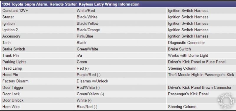
Here is a wire listing from a different source than your listing.
1. Horn(-) is listed as white (-)
2. Maybe your Supra does not have a Theft Module. Run the Hood wire out to the engine compartment with the supplied hood pin.
1997 Toyota Supra Last Update: 2/12/2009
Circuit Wire Color Location
Constant 12 volts WHITE & WHITE/ RED IGNITION SWITCH HARNESS
Ignition 12 volts BLACK/ WHITE IGNITION SWITCH HARNESS
Starter BLACK/ RED IGNITION SWITCH HARNESS
Dome Light RED / WHITE (-) 15 PIN CONNECTOR IN DR. KICK PANEL
Driver's Front Door Pin
Pass Front Door Pin
Driver's Rear Door Pin
Pass Rear Door Pin
Trunk Pin L GREEN (-) 13 PIN CONNECTOR IN DR. KICK PANEL
OEM Hood Pin
Parking Lamp (+) GREEN (+) 16 PIN CONNECTOR AT FUSE BLOCK
Parking Lamp (-)
Lock RED / WHITE 16 PIN BLUE CONNECTOR
Unlock GREEN/ RED IN DRIVER KICK PANEL * #209
* Child Safety Locks - BLUE/WHITE (-) In Same Connector As Door Lock Wires Above.
#209- See Child Safety Locks Diagram.
Tach Signal BLACK/ WHITE AT IGNITER OR ENGINE CONTROL MODULE *
Ignition Coil (-)
Injector (-)
Ignition #2 BLACK / YELLOW IGNITION SWITCH HARNESS
Ignition #3 N/A
Accessory GREEN IGNITION SWITCH HARNESS
Accessory #2
Accessory #3
Starter #2
Neutral Safety NOT GROUNDING TYPE - OEM SWITCH OPENS STARTER CIRCUIT
Brake Light GREEN / WHITE (+) AT SWITCH ABOVE BRAKE PEDAL
Parking Brake
Clutch Pedal
Reverse Light RED / BLACK (+) 13 PIN ORANGE CONN. IN DR. KICK PANEL
Rear Defrost N/A
Immobilizer Type
* Turbo Models - Tach Wire Is BLACK/ WHITE At Engine Control Module Located Below Passenger Dash. Non Turbo Models - Tach Wire IS BLACK/ WHITE At Igniter On Driver Strut Tower. On Both Models Tach Wire Can Also Be Found In 38 Pin Orange Connector Below Passenger Dash.
Window Up D\ RED / WHITE P\ RED / BLUE @ MAIN #211
Window Down R/ GREEN/ YELLOW S/ GREEN / WHITE SWITCH
Trunk Release N/A
Keysense YELLOW (-) IGNITION SWITCH HARNESS
OEM Horn WHITE (-) STEERING COLUMN HARNESS
Headlights RED OR YELLOW/RED (-) AT HEADLIGHT SWITCH
OEM Alarm Arm WHITE (-) 16 PIN BLUE CONNECTOR *
OEM Alarm Disarm GREEN/ YELLOW (-) IN DRIVER KICK PANEL
Vehicle Speed Sense
OEM Keyless Module - NO OEM KEYLESS PRESENT IN SCHEMATICS
Motor Lock N/A
Motor All Unlock N/A
Motor Driver Unlock
(disarm defeat) BLUE/RED 16 PIN CONNECTOR IN DR. KICK PANEL *
Trunk Release Disarm
OEM Lock Relays - DOOR LOCK CONTROL UNIT LOCATED IN PASSENGER KICK PANEL
Add On Security Type N/A
* Circuit Type - Reversal Rest At Ground.
-------------
When all else fails, Read the Instructions
Support the12volt.com Make a Donation
Posted By: golfer2000
Date Posted: January 01, 2017 at 11:34 AM
Thank you I will try another horn wire. And while I'd like to avoid hood pin, it's starting to look like my only option. How bad is it to keep that ign to something other than constant? The car remote starts fine as it is now. Thanks again.
Posted By: smokeman1
Date Posted: January 01, 2017 at 11:49 AM
I don't understand your question.
(How bad is it to keep that ign to something other than constant?)
-------------
When all else fails, Read the Instructions
Support the12volt.com Make a Donation
Posted By: golfer2000
Date Posted: January 01, 2017 at 11:59 AM
Currently I have my pink/white hooked up to BLACK/ orange (ign 2) not a 12v constant. It works but is this something I need to change to 12v constant?
Posted By: smokeman1
Date Posted: January 01, 2017 at 12:42 PM
The pink/white IS NOT suppose to be connected to a 12volt constant source. It is a output to your ignition 2 wire.
-------------
When all else fails, Read the Instructions
Support the12volt.com Make a Donation
Posted By: golfer2000
Date Posted: January 01, 2017 at 12:45 PM
I'm sorry the RED / white. I also have it hooked up to ign 2.
smokeman1 wrote:
The pink/white IS NOT suppose to be connected to a 12volt constant source. It is a output to your ignition 2 wire.
Posted By: smokeman1
Date Posted: January 01, 2017 at 3:53 PM
Your choice. The RED / White belongs to a 12volt constant, not an ignition wire
-------------
When all else fails, Read the Instructions
Support the12volt.com Make a Donation
Posted By: golfer2000
Date Posted: January 02, 2017 at 8:51 PM
Alright this is the new version. Everything okay now?
Posted By: golfer2000
Date Posted: January 02, 2017 at 11:13 PM
Okay when I had the ignition harness removed from the ignition plug I had 10milliamp draw and when I plugged it in (which is hooked up to remote start brain) I had a 30milliamp draw. Is this about avg? Is this something that can be lowered?
Thanks
Posted By: golfer2000
Date Posted: January 05, 2017 at 1:18 AM
Bump. I got a new battery and I'm concerned this draw will be harmful for it. In a matter of two days it's down to about 12.5v and dropping.
Posted By: golfer2000
Date Posted: January 05, 2017 at 11:11 PM
Anyone? This thing is almost done
Posted By: smokeman1
Date Posted: January 06, 2017 at 6:06 AM
If this is a new unit, the power draw, armed and standby, will be listed on the bottom of the box. The yellow/black box.
-------------
When all else fails, Read the Instructions
Support the12volt.com Make a Donation
Posted By: golfer2000
Date Posted: May 21, 2017 at 4:27 PM
Just a heads up my negative parking light wire in the steering column was clear. Not sure why there are so many discrepancies. Still looking for horn..
Posted By: golfer2000
Date Posted: May 21, 2017 at 4:28 PM
Horn wire ended up being green in the rubber loom with the tan red and white wires. Go figure lol
Posted By: shift_happens
Date Posted: May 23, 2017 at 11:59 AM
This post is only to say I would have sex with the rear end of a Supra.
I will show myself the door now.
Posted By: golfer2000
Date Posted: May 23, 2017 at 2:31 PM
shift_happens wrote:
This post is only to say I would have sex with the rear end of a Supra.
I will show myself the door now.
I'm with this guy 👍
Posted By: rottweilaz
Date Posted: June 25, 2018 at 10:36 PM
what pins do I need to use for the 24 pin connector?
|