Wiring 2015 Accord Sport, Compustar
Printed From: the12volt.com
Forum Name: Car Security and Convenience
Forum Discription: Car Alarms, Keyless Entries, Remote Starters, Immobilizer Bypasses, Sensors, Door Locks, Window Modules, Heated Mirrors, Heated Seats, etc.
URL: https://www.the12volt.com/installbay/forum_posts.asp?tid=142711
Printed Date: May 15, 2026 at 11:47 AM
Topic: Wiring 2015 Accord Sport, Compustar
Posted By: crazyboom
Subject: Wiring 2015 Accord Sport, Compustar
Date Posted: March 04, 2017 at 12:35 AM
Here's my info (THANKS to the member who posted the spreadsheet) can someone please check for errors?
Vehicle Information: 2015 HONDA ACCORD SPORT, 4 CYLINDER, AUTOMATIC TRANSMISSION, STANDARD KEY
Alarm / Remote Start Unit: COMPUSTAR 7000AS/Pro T11 2-WAY REMOTE
Bypass Module: IDATALINK BLADE-AL(DL)-HA6
Alarm / Remote Start / Bypass Unit Vehicle
Connection Connection
Color Description Color Polarity Location:
High Current Ignition Harness (CN1)
12V Constant (pin 1) Red Constant 12V "power wire" White (50 AMP) (+) Green Ignition connector above upper fuse box, or main ignition connector under steering
column
12V Selectable (Default Parking Light, pin 2) GREEN / WHITE Programmable output (+) Red (+) See Above
12V Constant (pin 3) RED / White Accessory and starter output White (50 AMP) (+) See Above
12V Selectable (Default Accessory (pin 4) White Accessory/HVAC blower motor Orange (+) See Above
12V Selectable (Default ignition 2, pin 5) Blue 2nd ign, 2nd acc, or parking lt out N/A (+)
12V Starter (pin 6) Yellow Starter 12V (+) output Blue (+) See Above
12V Ignition (pin 7) Green Ignition 12V (+) output/input Green (+) See Above
Ground Black Ground (-) To chassis ground (-) Vehicle chassis ground
Blade Connector (CN4)
Ignition connector side (pin 20) WHITE/ Black Brown (+) Transponder plug (pin 2) connector side
Ignition vehicle side (pin 10) WHITE/ Red Brown (+) Transponder plug (pin 2) vehicle side
CanH (pin 6) BROWN / Red Pink DATA Transponder plug (pin 4)
CanL (pin 16) BROWN / Yellow Blue DATA Transponder plug (pin 3)
Key Data ORANGE / Black Grey DATA Transponder plug (pin 6)
Ignition Input Pink Ties into WHITE/ Red on vehicle ignition side Brown (+) Transponder plug (pin 2) or ties into the WHITE/ Red wire from Blade Connector
Programmable Output Channel (CN5)
So far nada....
I also have a few questions:
1. I would like to wire the remote's AUX 1 to the window defroster... what wires can I use and do the brains need to be programmed? I know where to access the defroster wire and I have a weblink account and USB connector, but do not own an OP500...
2. I've read that the ground to chassis limits the RF signal range of the remote. Is there a better place to ground the system? Any experience with this situation?
3. Is it possible to wire a windows up feature as an aux? If so how hard and labor intensive is it?
4. I'd be wiring both the siren, and thermistor. Where is the best place to, and how would you mount them?
THANKS again for all your help!
Replies:
Posted By: crazyboom
Date Posted: March 09, 2017 at 11:06 PM
Can someone with more rest and a better knowledge of relays look at this and help me????
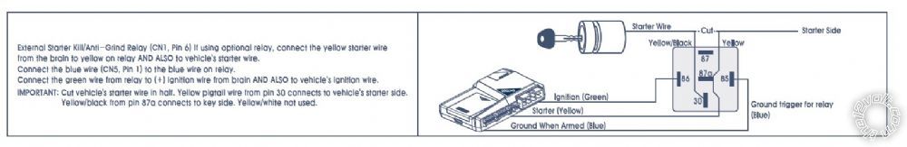
The instructions are pretty straight forward and include this diagram...

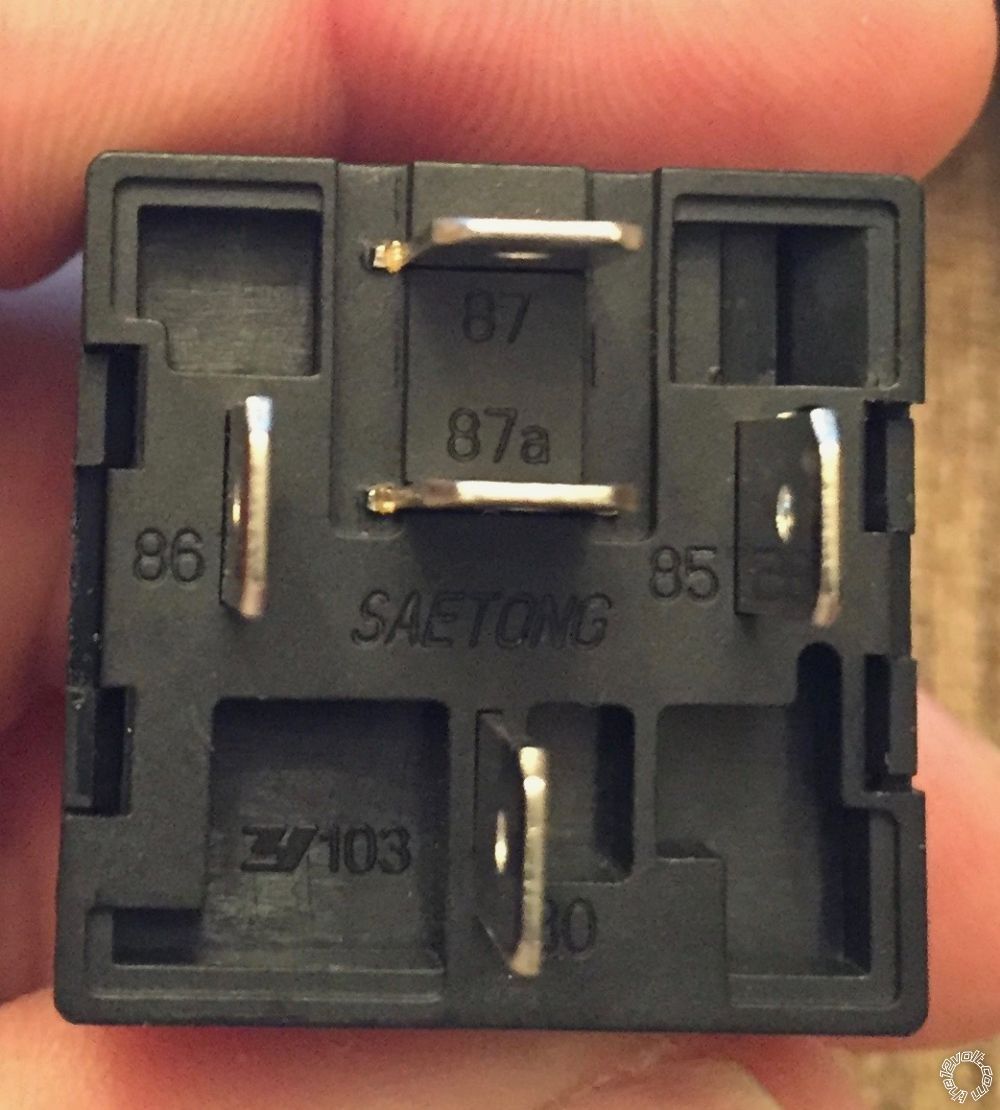
As you can see it shows 86 as the ignition/green wire and 85 as the ground trigger for relay/GWA blue wire from the RS. HOWEVER, when I compare the actual relay that was provided it appears these two have been switched. Am I imagining things? It seems that this flys in the face of conventional wisdom; however, I did just complete a 13 hr flight and probably shouldn't be tooling around with this stuff right now...
Any assistance is greatly appreciated...
Posted By: astuff
Date Posted: March 10, 2017 at 12:16 AM
Yes, it is different from drawing but does not make a difference except for debugging purposes. 85 and 86 go to the coil that activates the relay and can be reversed without issue.
Posted By: kaezoo
Date Posted: March 10, 2017 at 5:19 AM
It actually doesn't matter. A relay like this will activate with voltage on one coil terminal and ground on the other, and if you reverse the connections it won't hurt anything.
Some relays have a diode placed between terminals 85 and 86, and with these relays you'd need to pay attention to the polarity of the connections. Without the diode, they're interchangeable.
Posted By: crazyboom
Date Posted: March 10, 2017 at 7:45 AM
Thank you!
I knew that there was something I was missing! I never even looked to see if the relay had a diode...
Posted By: crazyboom
Date Posted: March 10, 2017 at 7:47 AM
Thank you!
After a full nights sleep I'm able to see much more clearly and your answer confirmed my thoughts. I didn't even think to check for a diode ...
Posted By: crazyboom
Date Posted: March 11, 2017 at 9:07 AM
I'm looking for the wiring diagram of the 2013-2015 Honda Accord window controls. Trying to add the vent feature to an AUX off of a Compustar 7000AS.
Thanks!
Posted By: crazyboom
Date Posted: March 11, 2017 at 9:11 AM
Week-end warriors, install professionals, and DIY'ers
Now that I have your attention...
I'm installing a Compustar 7000AS and would like to know if there are any reasons not to install the supplied system LED? Why not? On the flip side where would you place it? It's going into a 2015 Honda Accord Sport...
Thanks!!
Posted By: crazyboom
Date Posted: March 11, 2017 at 9:25 AM
When the weather is to cold to work on your ride outside, or take your scoot for a spin, great minds turn to unsolved mysteries...please help me solve mine.
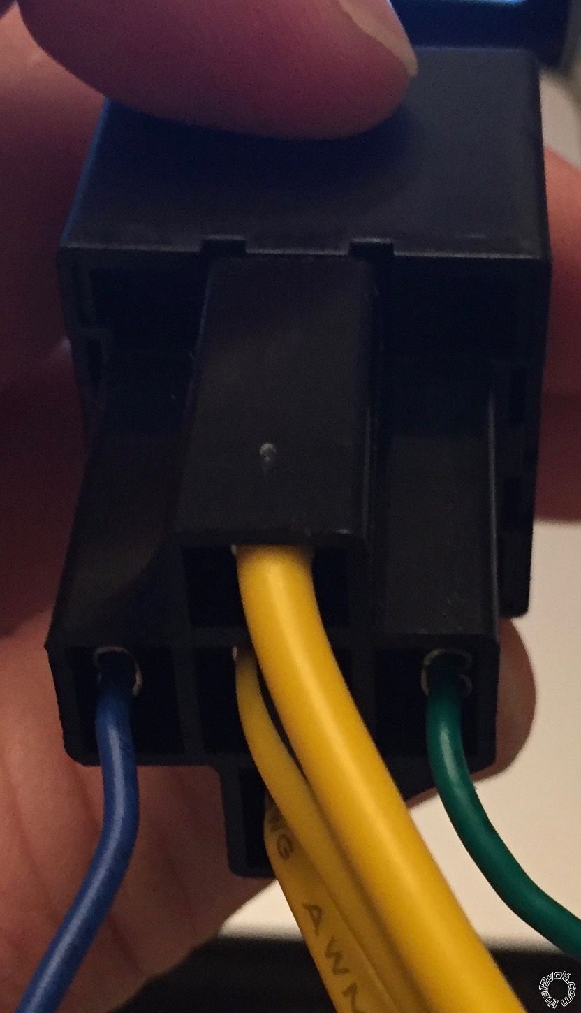
I have a relay installed on a Compustar 7000AS for anti-grind/starter kill, wired as pictured below.
I would like to add the ability to vent my windows using the AUX 1 output (it can provide a 250 mA (-) signal for 0.5 seconds or is programmable up to 99 seconds, but has no "validity" mode like other systems). The end goal is to enable AUX 1 to vent the windows at almost any time, just not during start up. I believe that at a minimum I'll need to borrow the GWA from the 7000AS (wire I used in the anti-grind relay), add some diodes, and if I'm not mistaken it may be best to add another relay. How would you wire all this to achieve the desired effects?
Thanks!
Posted By: kreg357
Date Posted: March 11, 2017 at 9:35 AM
As far as installing it, it's your choice. It gives an additional indication of the added alarms status, both as a theft deterrent or helpful indicator for you. If you want to use it primarily as a theft deterrent ( the car already has a Factory Alarm system and an ignition immobilizer system ) you would want to mount the LED in a easily visible area. Personally, I prefer not to drill extra holes in cars so if I mounted it, I would place in in one of the dash knock plugs ( where heated seat control, fog light switches, etc go ). That way it would be somewhat visible, easy to install and reversible later on by obtaining an inexpensive new / unmolested plug from the dealer or scrap yard.
-------------
Soldering is fun!
|