cm7200 and fortin int-sl+
Printed From: the12volt.com
Forum Name: Car Security and Convenience
Forum Discription: Car Alarms, Keyless Entries, Remote Starters, Immobilizer Bypasses, Sensors, Door Locks, Window Modules, Heated Mirrors, Heated Seats, etc.
URL: https://www.the12volt.com/installbay/forum_posts.asp?tid=142721
Printed Date: May 15, 2026 at 4:48 PM
Topic: cm7200 and fortin int-sl+
Posted By: iluvgunz
Subject: cm7200 and fortin int-sl+
Date Posted: March 06, 2017 at 10:45 AM
I am trying to instal a cm7200 remote start and fortin int-sl+ bypass in my 2001 jeep grand cherokee. I used to be a professional installer back in the early 90's. I still have a passion for car audio but I just do it for my own vehicles now and then. I was hoping that someone might be able to help me out with a vehicle specific install guide from compustar as I am not a dealer. I know where all my wires in the truck are, I am just trying to figure out which wires I need from the 20 pin harness on the cm7200. Seems like this compustar has a lot more options/wires than what I remember back in the day :) The main high voltage power harness is all wired up just trying to figure out the twenty pin on the cm7200. It looks like I only need four wires on the bypass and the rs-232 to the remote start. the generic guide for the cm7200 was of no help.
Thanks again
Tom
Replies:
Posted By: iluvgunz
Date Posted: March 06, 2017 at 11:11 AM
I should also say that I'm just looking to lock/unlock the doors and start the truck.
Posted By: iluvgunz
Date Posted: March 06, 2017 at 5:40 PM
Anyone have access to computech3.com?
It would be greatly appreciated
2001 jeep grand cherokee laredo
Posted By: kreg357
Date Posted: March 06, 2017 at 6:41 PM
Here is the full CM7200-s manual :
https://techfeed.compustar.com/ft_controllers/manuals/CM7200_Full_Install_3.00_EN.pdf
Here is a Pictorial on your Jeep using an iDatalink bypass module :
https://www.the12volt.com/installbay/forum_posts.asp?tid=137527
-------------
Soldering is fun!
Posted By: iluvgunz
Date Posted: March 06, 2017 at 6:54 PM
Thank you for the reply. Ive seen both those documents and what they all leave out are the connections that are made between the bypass and the remote start
Posted By: kreg357
Date Posted: March 06, 2017 at 7:04 PM
Personally, I would go W2W between the two modules. I can make up a chart for you if you wish.
-------------
Soldering is fun!
Posted By: iluvgunz
Date Posted: March 06, 2017 at 7:30 PM
These are the wiring schematics that I have. Its just making the connection between the two besides the rs-232.
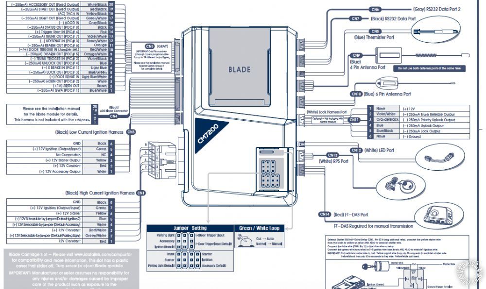
A chart would be awesome! I am a visual learner. CN5 is the harness on the cm7200 that i am working with. CN1 is already wired up.
Posted By: kreg357
Date Posted: March 06, 2017 at 8:05 PM
For me, W2W is easier to visualize. It makes sense with easy to follow hardwired connections. It takes a bit longer but
provides reliable results. Here is the wiring.
CM7200-s CN5
1 Blue/White POC#1 GWA not used
2 Brown Siren Out not used
3 White POC#2 Horn Jeep Gray/Orange @ Steering Column connector
4 Light Blue/White (+) Foot Brake In Jeep WHITE/ Tan @ Brake Pedal
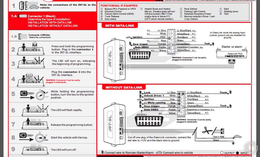
5 Blue/Black POC#3 Lock INT-SL+ Light Blue
6 Light Blue (-) E Brake In not used ( manual transmission only )
7 Blue POC#4 Unlock INT-SL+ White
8 Violet/Black(-) Trunk Trigger not used ( MT and alarm system )
9 ORANGE / WhitePOC#5 Disarm not used
10 RED / White Door Trigger In (+/-) not used ( MT and alarm system )
11 Orange POC#6 Rearmnot used
12 BROWN / White(-)Keysense In not used
13 Violet/White POC#7 TrunkINT-SL+ Light Blue/Black
14 Pink (+) Trigger Start In not used
15 Black POC#8 Status Out INT-SL+ Blue
16 Gray/Black (-)Hood In to kit supplied hood pin
17 GREEN / WHITE(-) Parking Light Out not used
18 Yellow/Black Tach In INT-SL+ Orange Black
19 RED / Black (-) Start Out not used
20 WHITE/ Black(-) ACC Outnot used
For the Parking Light, get a 30/40 Amp SPDT relay and wire as follows :
Relay Pin 85 to Chassis Ground
Relay Pin 86 to CM7200-s CN1 Pin 2 GREEN / WHITE (+) Parking Light Output
Relay Pin 87 to Chassis Ground through 1300 ohm resistor
Relay Pin 30 to Jeep Yellow Parking Light MUX wire shown in Pictorial
-------------
Soldering is fun!
Posted By: iluvgunz
Date Posted: March 06, 2017 at 9:05 PM
First I'd like to thank you! this has helped ENORMOUSLY! The way that I was going to wire it was using the data link then only needing four connections to the cm-7200. It looks like you prefer the without datalink method. Second I forgot to mention the factory alarm arm/disarm. Also what kind if info/data does the INT-SL pull from the OBD2 connection. It doesn't look like a true can bus system are no hi and low can bus wires.
Thank you again for the tremendous help!
Posted By: kreg357
Date Posted: March 07, 2017 at 3:34 AM
I have found that W2W always works while D2D can sometimes be temperamental. Additionally, there are 3
different D2D communication type formats, so matching the R/S to the bypass module is a big factor.
You will still need to make those 4 connections between the INT-SL+ and the Jeep. As you can see in
the Pictorial, the iDatalink bypass module also provides the Brake signal while the INT-SL+ does not.
The older J1850 connection at the ignition connector is the predecessor to the newer CAN systems. It
is a Data bus system. Typically, that connection can supply signals like Tach, Brake and Door Triggers.
It can also accept commands for Lock, Unlock, Trunk release, Arm, Disarm and the transponder bypass
data.
In the Jeeps case, with the Factory alarm, a Lock will also Arm the Factory alarm system and an Unlock
will Disarm it. That is the way the INT-SL+ handles those functions.
-------------
Soldering is fun!
Posted By: iluvgunz
Date Posted: March 07, 2017 at 7:35 AM
Thank you sooo much! That is exactly what I was looking for. An explanation of how the bypass handled everything plus the chart is a great help. I really appreciate your time . Thank you again
Posted By: windog
Date Posted: March 14, 2017 at 7:13 PM
I wish forum users would be totally honest when they ask for help. Instead what I find is that as you answer one question you realise that your generosity causes you to be sucked in beyond your expectations. this Jeep guy says that idatalink and fortin did not make any reference to the remote starter. This could not be true as he was not using a standalone bypass module. From my experience the bypass diagrams always show the wires -both input and output at the remote starter and the bypass module. Please get real and honest when you ask for help on this forum, It makes helping a real pleasure and is more satisfying.
|