Avital Remote Start Install, 03 Ford F-250
Printed From: the12volt.comForum Name: Car Security and Convenience
Forum Discription: Car Alarms, Keyless Entries, Remote Starters, Immobilizer Bypasses, Sensors, Door Locks, Window Modules, Heated Mirrors, Heated Seats, etc.
URL: https://www.the12volt.com/installbay/forum_posts.asp?tid=143583
Printed Date: May 14, 2026 at 2:25 AM
Topic: Avital Remote Start Install, 03 Ford F-250
Posted By: reptar
Subject: Avital Remote Start Install, 03 Ford F-250
Date Posted: September 29, 2017 at 10:23 PM
Hello all!
Before I dig into this I want to please beg some help out of people to confirm I've got all my wiring down.
Any help or guidance is very appreciated! Thank you in advance! All also post this revised once I get it all right to help someone else out down the road.
-On a 2003 F-250 XLT 4x4/ Factory door unlock/lock key fob / No alarm
-With a Avital 4115L Remote start 1-Way 1 button system.
I've written out everything I've gotten so far & left ???? in places I don't get.
Would love someone that can confidently tell me I've gotten things right or wrong.
Also using https://www.bulldogsecurity.com/bdnew/vehiclewiringdiagrams.aspx for my wiring reference for my truck.
Avital 4115L 1-Way Remote Engine Start
Primary Harness, White 9-pin Connector
1. LIGHT GREEN BLACK (-) 200ma Factory Alarm Disarm Output (NOT USED)
2. GREEN/WHITE (-) 200ma Factory Alarm Rearm Output (NOT USED)
3. YELLOW (+) Ignition Out (To Alarm) (NOT USED?????)
4. WHITE/BLUE (-) Activation input (?????)
5. ORANGE (-) 500ma Ground when locked/anti-grind output ??????
6. BROWN (-) 200ma Horn output (Dark Blue/ Steering Column)
7. RED/WHITE (-) 200ma Trunk Release output (NOT USED)
8. BLACK (-) Chassis Ground (Any ground under dash)
9. WHITE (+/-) Light flash Output (+ Brown, Headlight Switch)
Remote Start Harness, White 5-Pin Connector
1.BLACK/WHITE (-) Parking Brake Input** (CAN I OVERIDE? Mines shot./ Simply Ground this wire right?
**(Connect this wire the the (-) Parking brake wire in the vehicle. The parking brake must be applied for the remote start to work.)
2.VIOLET/WHITE Tachometer Input (?? Ignition coil wire??)
3.BROWN (+) Brake Shutdown Input (Light Green (+) Brake Pedal)
4.GRAY (-) Hood Pin Switch Shutdown Input (Supplied Switch)
5.BLUE/WHITE (-)200ma 2nd Status/Rear Defogger Output (NOT USED)
Heavy Gauge Relay, White 6-Pin Connector
1.RED (+) (30A) High Current 12V Input (12 Constant/ Yellow (+) Ign.)
2.PINK/WHITE (+)Second Ignition/accessory Cir. Output (NOT USED?????)
3.RED (+)(30A) High Current 12v Input (Constant/ Light Green Purple
4.ORANGE (+)Accessory Output (Not USED)
5.PURPLE (+)Starter Output (Starter Wire Green)
6.PINK (+) Ignition 1 Input/output (White/Yellow)
Satellite Harness White 4-Pin Connector (DONT BELIEVE I USE)
1.BLUE (-) 200ma Status Output
2.ORANGE (-) 200ma Accessory Output
3.PURPLE (-) 200ma Starter output
4.PINK (-) 200ma Ignition Output
Door Lock, White 3-Pin Connector (NOT USING)
1.LIGHT BLUE (-) 200ma Unlock Output
2.EMPTY
3.GREEN (-) 200ma Lock Output
D2D Harness, Red 4-Pin Connector (NOT USING)
1.BLUE D2D TX
2.BLACK (-) Ground
3.GREEN D2D RX
4.RED (+) 12v
Bitwriter/ Directed Smartstart Harness, Black 3-Pin Connector (NOT USING)
1.RED (+) 12v
2.ORANGE ESP2 RX/TX
3.BLACK (-) Ground
Replies:
Posted By: kreg357
Date Posted: September 29, 2017 at 10:40 PM
This Pictorial on your truck should help :
https://www.the12volt.com/installbay/forum_posts.asp?tid=133810
Need some more info. Which engine? Auto or Manual transmission? Power door locks?
-------------
Soldering is fun!
https://www.the12volt.com/installbay/forum_posts.asp?tid=133810
Need some more info. Which engine? Auto or Manual transmission? Power door locks?
-------------
Soldering is fun!
Posted By: reptar
Date Posted: September 29, 2017 at 11:05 PM
Trition 5.4 gas, auto transmission with tow haul button, yes it has power door locks.
Thank you!
Thank you!
Posted By: reptar
Date Posted: September 29, 2017 at 11:07 PM
Awesome link with really useful pictures! Thank you!
Posted By: kreg357
Date Posted: September 30, 2017 at 8:11 AM
Next question, does the truck have remote keyless entry ( FOB's for lock/unlock )?
As you can see in the Pictorial, there are many ignition wires. While you might be able to remote start your truck with the few wires you listed above, if you want the heat / AC to work ( fans ), you must power additional wires.
Another thing you should check is if your truck has the PATS ignition immobilizer system. The easy way is to see if the truck will start with a plain $1.99 hardware store key, copied from one of the working factory original keys. Or you could wrap the head area of the factory key with several layers of aluminum foil and try to start the truck. Most don't have chipped keys but it's best to test first, before install.
-------------
Soldering is fun!
Posted By: kreg357
Date Posted: September 30, 2017 at 8:12 AM
Wiring :
Primary Harness, White 9-pin Connector
1. LIGHT GREEN BLACK (-) 200ma Factory Alarm Disarm Output (NOT USED)
2. GREEN/WHITE (-) 200ma Factory Alarm Rearm Output (NOT USED)
3. YELLOW (+) Ignition Out (To Alarm) (NOT USED)
4. WHITE/BLUE (-) Activation input ( not used )
5. ORANGE (-) 500ma Ground when locked/anti-grind output ( not used unless you want anti-grind )
6. BROWN (-) 200ma Horn output (Dark Blue/ Steering Column)
7. RED/WHITE (-) 200ma Trunk Release output (NOT USED)
8. BLACK (-) Chassis Ground (Any ground under dash)
9. WHITE (+/-) Light flash Output (+ Brown, Headlight Switch)
-------------
Soldering is fun!
Posted By: kreg357
Date Posted: September 30, 2017 at 8:19 AM
You should grab a test light or multi-meter to check your ignition wires to determine the Starter wire, Ignition wires and the Accessory wires.
They should be pretty much what's listed in the Pictorial. Here is the basics :
Starter wire = +12V only when key is turned to the START position, 0 V in other positions
Ignition wire = +12V when key is in ON and stays at +12V in the Start positions
Accessory wire = +12V in ACC position and drops to 0 V in the START position
I like to power all the ignition wires just like the key does. No surprises and the truck is happy. This will require extra relays and wiring.
-------------
Soldering is fun!
Posted By: kreg357
Date Posted: September 30, 2017 at 10:11 AM
Heavy Gauge Relay, White 6-Pin Connector
1.RED (+) (30A) High Current 12V Input (12 Constant/ Yellow#1 (+) @ Ign.)
2.PINK/WHITE (+)Second Ignition/accessory Cir. Output RED/BLACK (+) @ IGNITION SWITCH HARNESS
3.RED (+)(30A) High Current 12v Input (12V Constant Light Green/ Purple)
4.ORANGE (+)Accessory Output GRAY/YELLOW (+) @ IGNITION SWITCH HARNESS
5.PURPLE (+)Starter Output (Starter Wire Green)
6.PINK (+) Ignition 1 Input/output (White/Yellow)
Remote Start Harness, White 5-Pin Connector
1.BLACK/WHITE (-) Parking Brake Input** to Chassis Ground if Auto Trans ( 4115 is Auto Trans only )
2.VIOLET/WHITE Tachometer Input Ignition coil wire ( not Red/Light Green )
3.BROWN (+) Brake Shutdown Input (Light Green (+) Brake Pedal)
4.GRAY (-) Hood Pin Switch Shutdown Input (Supplied Switch)
5.BLUE/WHITE (-)200ma 2nd Status/Rear Defogger Output (NOT USED)
Satellite Harness White 4-Pin Connector (DONT BELIEVE I USE)
1.BLUE (-) 200ma Status Output not used unless truck has PATS
2.ORANGE (-) 200ma Accessory Output to extra realy, Pin 85 for ACC2 wire
3.PURPLE (-) 200ma Starter output not used
4.PINK (-) 200ma Ignition Output not used
Extra 30/40 Amp SPDT relay for ACC2
Relay Pins 86 and 87 to Yellow #2 at ignition harness through 30 amp fuse
Relay Pin 85 to Viper Orange at Pin 2 of Satellite plug
Relay Pin 30 to ACC2 DARK BLUE/LIGHT GREEN (+) @ IGNITION SWITCH HARNESS
-------------
Soldering is fun!
Posted By: kreg357
Date Posted: September 30, 2017 at 10:14 AM
If you don't have RKE, now would have been to time to add it. Not much of a price difference between the
Viper 4115 and the 4105. You can still get some extra bang for your buck by adding the Viper 4115 Unlock
while remote started feature. If your truck does not have Factory RKE, you will need another 30/40 Amp
SPDT relay.
-------------
Soldering is fun!
Viper 4115 and the 4105. You can still get some extra bang for your buck by adding the Viper 4115 Unlock
while remote started feature. If your truck does not have Factory RKE, you will need another 30/40 Amp
SPDT relay.
-------------
Soldering is fun!
Posted By: reptar
Date Posted: September 30, 2017 at 2:22 PM
kreg357 wrote:
Next question, does the truck have remote keyless entry ( FOB's for lock/unlock )?
As you can see in the Pictorial, there are many ignition wires. While you might be able to remote start your truck with the few wires you listed above, if you want the heat / AC to work ( fans ), you must power additional wires.
Another thing you should check is if your truck has the PATS ignition immobilizer system. The easy way is to see if the truck will start with a plain $1.99 hardware store key, copied from one of the working factory original keys. Or you could wrap the head area of the factory key with several layers of aluminum foil and try to start the truck. Most don't have chipped keys but it's best to test first, before install.
Definitely does not have any chipped keys or fobs. I'm starring at a plain old metal copied key Ive used many a times to start and run it.
So your saying all need to use all of the wires or add more than the Heavy Gauge Relay, White 6-Pin Connector for fans?
Thank you!
Posted By: reptar
Date Posted: September 30, 2017 at 2:30 PM
kreg357 wrote:
If you don't have RKE, now would have been to time to add it. Not much of a price difference between the
Viper 4115 and the 4105. You can still get some extra bang for your buck by adding the Viper 4115 Unlock
while remote started feature. If your truck does not have Factory RKE, you will need another 30/40 Amp
SPDT relay.
Man kreg357 thank you so much for coping and updating my wiring codes!
My trucks a gasser so I can still tap into that Ignition coil wire above spark plugs & not behind my cluster?
Also yes I'm going to ask, what is RKE?? A unlock/lock key fob?
I have the factory unlock & lock remote & don't you have to had a relay for the unlock & lock function to work? Figured its less
cutting into my wires & simpler without.
Posted By: reptar
Date Posted: September 30, 2017 at 2:34 PM
kreg357 wrote:
Satellite Harness White 4-Pin Connector (DONT BELIEVE I USE)
1.BLUE (-) 200ma Status Output not used unless truck has PATS
2.ORANGE (-) 200ma Accessory Output to extra realy, Pin 85 for ACC2 wire
3.PURPLE (-) 200ma Starter output not used
4.PINK (-) 200ma Ignition Output not used
Extra 30/40 Amp SPDT relay for ACC2
Relay Pins 86 and 87 to Yellow #2 at ignition harness through 30 amp fuse
Relay Pin 85 to Viper Orange at Pin 2 of Satellite plug
Relay Pin 30 to ACC2 DARK BLUE/LIGHT GREEN (+) @ IGNITION SWITCH HARNESS
So I only use this if I have pats correct?
Posted By: reptar
Date Posted: September 30, 2017 at 2:44 PM
Also yes I would like anti-grind for my peace of mind. That just means I have to hook up the tach wire right?
Also sorry I would of tried to keep this forum cleaner but I cant find any edit button for my posts. Seems like you have to upgrade your account for it?
Thanks!
Also sorry I would of tried to keep this forum cleaner but I cant find any edit button for my posts. Seems like you have to upgrade your account for it?
Thanks!
Posted By: reptar
Date Posted: September 30, 2017 at 3:43 PM
**UPDATED** NO CHIPPED KEY, 5.4 GAS AUTO TRANS.
Primary Harness, White 9-pin Connector
1. LIGHT GREEN BLACK (-) 200ma Factory Alarm Disarm Output (NOT USED)
2. GREEN/WHITE (-) 200ma Factory Alarm Rearm Output (NOT USED)
3. YELLOW (+) Ignition Out (To Alarm) (NOT USED)
4. WHITE/BLUE (-) Activation input (NOT USED)
5. ORANGE (-) 500ma Ground when locked/anti-grind output ???? STILL DONT GET?
6. BROWN (-) 200ma Horn output (Dark Blue/ Steering Column)
7. RED/WHITE (-) 200ma Trunk Release output (NOT USED)
8. BLACK (-) Chassis Ground (Any ground under dash)
9. WHITE (+/-) Light flash Output (+ Brown, Headlight Switch)
Remote Start Harness, White 5-Pin Connector
1.BLACK/WHITE (-) Parking Brake Input** TO CHASSIS GROUND
**(Connect this wire the the (-) Parking brake wire in the vehicle. The parking brake must be applied for the remote start to work.)
2.VIOLET/WHITE Tachometer Input (IGNITION COIL WIRE/ NOT RED/LIGHT GREEN
3.BROWN (+) Brake Shutdown Input (Light Green (+) Brake Pedal)
4.GRAY (-) Hood Pin Switch Shutdown Input (Supplied Switch)
5.BLUE/WHITE (-)200ma 2nd Status/Rear Defogger Output (NOT USED)
Heavy Gauge Relay, White 6-Pin Connector
1.RED (+) (30A) High Current 12V Input (12 Constant/ Yellow (+) Ign.)
2.PINK/WHITE (+)Second Ignition/accessory Cir. Output RED/BLACK(+) IGN
3.RED (+)(30A) High Current 12v Input (Constant/ Light Green Purple
4.ORANGE (+)Accessory Output GREY/YELLOW IGN
5.PURPLE (+)Starter Output (Starter Wire Green)
6.PINK (+) Ignition 1 Input/output (White/Yellow)
Satellite Harness White 4-Pin Connector (DONT BELIEVE I USE)
1.BLUE (-) 200ma Status Output
2.ORANGE (-) 200ma Accessory Output
3.PURPLE (-) 200ma Starter output
4.PINK (-) 200ma Ignition Output
Door Lock, White 3-Pin Connector (NOT USING)
1.LIGHT BLUE (-) 200ma Unlock Output
2.EMPTY
3.GREEN (-) 200ma Lock Output
D2D Harness, Red 4-Pin Connector (NOT USING)
1.BLUE D2D TX
2.BLACK (-) Ground
3.GREEN D2D RX
4.RED (+) 12v
Bitwriter/ Directed Smartstart Harness, Black 3-Pin Connector (NOT USING)
1.RED (+) 12v
2.ORANGE ESP2 RX/TX
3.BLACK (-) Ground
Posted By: kreg357
Date Posted: September 30, 2017 at 4:44 PM
No chipped keys means you don't need a bypass module or use the Blue (-) Status Output wire. The 4115 and the extra relay
will handle everything.
The extra relay will be used in conjunction with the Vipers thin (-) Accessory output wire to power the trucks ACC2 wire.
The wiring was shown above. This extra ACC wire has nothing to do with PATS and chipped keys. I would still power
ACC2 but you can try it without. It might only power the radio, wipers, windows and unnecessary things like that.
The TACH connection will allow the Viper to crank the engine enough to start but not too long to get that drag over-run.
This is a good feature if you have big seasonal temperature swings. A cold day with a cold engine usually requires extra
crank time to get it running. Much more reliable than Virtual Tach.
The Anti-Grind feature mentioned is to prevent you from engaging the starter again during key-takerover if you were
to turn the key too far. It's optional and would require another 30/40 Amp relay and extra wiring using (-) Status Output.
Using Ground When Locked won't really work with a 4115 because your Viper one button FOB doesn't do Lock.
RKE means Remote Keyless Entry, as in the Ford FOB's that will lock and unlock the truck at a short distance.
If you have RKE, you could use the 4115 feature that allows you to use the single button FOB to unlock the doors
while the truck is remote started. All that would be needed is a direct connection from the 4115 (-) Unlock wire to
the trucks Unlock wire. Without factory RKE, you would need another 30/40 Amp SPDT relay to interface with
the trucks Unlock wire ( 5 wire reverse vs (-) Type B locking system ).
-------------
Soldering is fun!
Posted By: reptar
Date Posted: September 30, 2017 at 8:24 PM
kreg357 wrote:
The 4115 and the extra relay will handle everything.
The extra relay will be used in conjunction with the Vipers thin (-) Accessory output wire to power the trucks ACC2 wire.
The wiring was shown above. This extra ACC wire has nothing to do with PATS and chipped keys. I would still power
ACC2 but you can try it without. It might only power the radio, wipers, windows and unnecessary things like that.
The TACH connection will allow the Viper to crank the engine enough to start but not too long to get that drag over-run.
This is a good feature if you have big seasonal temperature swings. A cold day with a cold engine usually requires extra
crank time to get it running. Much more reliable than Virtual Tach.
The Anti-Grind feature mentioned is to prevent you from engaging the starter again during key-takerover if you were
to turn the key too far. It's optional and would require another 30/40 Amp relay and extra wiring using (-) Status Output.
Using Ground When Locked won't really work with a 4115 because your Viper one button FOB doesn't do Lock.
K I think I've got most of that!
Defiantly going to run the Tach wire as winter is approaching & it can get pretty cold here in the Pacific Northwest on occasion.
If I wanted I would need two extra relays,
1. To power my accessories, radio, blower mabye? ect.
2. Another relay to use the Anti-Grind feature during key takeover.
If you or anyone else is up to it, could you explain how to wire the relays?
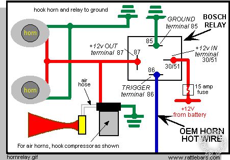
So I believe this is the correct type of relay image I've found.
So for
1. My accessories I would
85 -Run To Ground
87 -2nd trucks accessory wire?
86 trigger with (Satellite Harness White 4-Pin Connector
2.ORANGE (-) 200ma Accessory Output)
30/51- Power for 12v+ from battery or other source
For anti-grind feature I would
85-to ground
87- Primary Harness, White 9-pin Connector5. ORANGE (-) 500ma Ground when locked/anti-grind output
86-Trigger with (Satellite Harness White 4-Pin Connector
1.BLUE(-) 200ma Status Output)
30/51- Power for 12v+ from battery or other source
Posted By: kreg357
Date Posted: September 30, 2017 at 11:13 PM
One of the relays would be used to power the trucks ACC2 circuit. I am not sure what is controlled by
the ACC2 circuit. It could be things like radio, power windows, wipers, etc. Might not be those items.
I have never tried to find out as I always power it. This ACC2 relay would be wired as below :
Relay Pin 86 and 87 to +12V constant Yellow #2 at the ignition switch through 30 Amp fuse
Relay Pin 85 to Avital 4115 thin Orange (-) Accessory Output
Relay Pin 30 to ACC2 DARK BLUE/LIGHT GREEN (+) @ IGNITION SWITCH HARNESS
Relay Pin 87a not used
This was shown on Page 1.
The second relay would be for the optional Anti-Grind. This feature would reguire you to cut the trucks
Dark Green Starter wire and make a slight wire deviation from the previously posted listing. It would be
wired as below :
Relay Pin 85 to Avital Dark Blue (-) Status Output
Relay Pin 86 to +12V constant ( either Yellow or the Light Green/Violet wire )
Relay Pin 87a to ignition switch side of cut Dark Green Starter wire
Relay Pin 30 to vehicle side of cut Dark Green Starter wire
Relay Pin 87 to Avital thick (+) Purple Starter Output
Please note that the Avital thick (+) Purple Starter Output wire must connect to the vehicle side of the cut
Dark Green Starter wire. It could go to Pin 30 of the Relay also, but then you would have to connect two
wires to Pin 30. It is easier to use the energized relay's Pin 87 to send the Starter signal to the truck.
How the Anti-Grind relay works :
During normal key start up, the relay is in a de-energized state. As such Pins 30 and 87a are NC ( normally
closed ) and will allow the +12V Starter signal from the ignition switch through and the starter will crank.
During a remote start, the (-) Status Output signal goes true and outputs a Chassis Ground during the entire
remote start sequence. This (-) Status output signal energizes the relay and opens its' internal connection
between Pins 87a to 30 and makes the connection between Pin 87 and 30. This does two things. It prevents
the ignition switch (+) Starter signal from getting through the relay and cranking the starter motor. It
allows the Avitals Starter Output to go from Pin 87 to Pin 30 and on to the starter motor to start the engine.
The Anti-Grind feature works because the relay is energized during the entire remote start period, so if you
get into the truck, insert the key into the ignition switch and inadvertly go past ON and hit the START area,
the ignition switches +12V Starter signal would not go through the open relay contacts ( Pin 87a to 30 )
and cause a starter grind.
-------------
Soldering is fun!
Posted By: kreg357
Date Posted: September 30, 2017 at 11:29 PM
Updated wiring with ACC2 and Anti-Grind relays.
Primary Harness, White 9-pin Connector
1. LIGHT GREEN BLACK (-) 200ma Factory Alarm Disarm Output (NOT USED)
2. GREEN/WHITE (-) 200ma Factory Alarm Rearm Output (NOT USED)
3. YELLOW (+) Ignition Out (To Alarm) (NOT USED)
4. WHITE/BLUE (-) Activation input (NOT USED)
5. ORANGE (-) 500ma Ground when locked/anti-grind output (NOT USED)
6. BROWN (-) 200ma Horn output (Dark Blue/ Steering Column)
7. RED/WHITE (-) 200ma Trunk Release output (NOT USED)
8. BLACK (-) Chassis Ground (Any solid rust/paint free area of frame using soldered-on terminal ring)
9. WHITE (+/-) Light flash Output * (+ Brown, Headlight Switch)
* Set 4115 Parking Light jumper to (+) output
Remote Start Harness, White 5-Pin Connector
1.BLACK/WHITE (-) Parking Brake Input TO CHASSIS GROUND
2.VIOLET/WHITE Tachometer Input (any IGNITION COIL WIRE that is NOT RED/LIGHT GREEN)
3.BROWN (+) Brake Shutdown Input (Light Green (+) Brake Pedal switch)
4.GRAY (-) Hood Pin Switch Shutdown Input (Supplied Switch)
5.BLUE/WHITE (-)200ma 2nd Status/Rear Defogger Output (NOT USED)
Heavy Gauge Relay, White 6-Pin Connector
1.RED (+) (30A) High Current 12V Input (12 Constant/ Yellow#1 @ (+) Ign.)
2.PINK/WHITE (+)Second Ignition/accessory RED/BLACK(+) @ IGN
3.RED (+)(30A) High Current 12v Input (Constant 12V Light Green Purple )
4.ORANGE (+)Accessory Output GREY/YELLOW @ IGN
5.PURPLE (+)Starter Output Anti-Grind Relay, Pin 87
6.PINK (+) Ignition 1 Input/output (White/Yellow)
Anti-Grind Relay
Relay Pin 85 to Avital Dark Blue (-) Status Output
Relay Pin 86 to +12V constant ( either Yellow or the Light Green/Violet wire )
Relay Pin 87a to ignition switch side of cut Dark Green Starter wire
Relay Pin 30 to vehicle side of cut Dark Green Starter wire
Relay Pin 87 to Avital thick (+) Purple Starter Output
ACC2 Relay
Relay Pin 86 and 87 to +12V constant Yellow #2 at the ignition switch through 30 Amp fuse
Relay Pin 85 to Avital 4115 thin Orange (-) Accessory Output
Relay Pin 30 to ACC2 DARK BLUE/LIGHT GREEN (+) @ IGNITION SWITCH HARNESS
Relay Pin 87a not used
Satellite Harness White 4-Pin Connector
1.BLUE (-) 200ma Status Output Anti-Grind Relay Pin 85
2.ORANGE (-) 200ma Accessory Output ACC2 Relay Pin 85
3.PURPLE (-) 200ma Starter output (NOT USED)
4.PINK (-) 200ma Ignition Output (NOT USED)
Door Lock, White 3-Pin Connector
1.LIGHT BLUE (-) 200ma Unlock Output ** BLACK/WHITE (-) at the VSM or in the DRIVERS DOOR HARNESS
2.EMPTY
3.GREEN (-) 200ma Lock Output
** If truck has Factory RKE and Ford FOBs
D2D Harness, Red 4-Pin Connector (NOT USING)
1.BLUE D2D TX
2.BLACK (-) Ground
3.GREEN D2D RX
4.RED (+) 12v
Bitwriter/ Directed Smartstart Harness, Black 3-Pin Connector (NOT USING)
1.RED (+) 12v
2.ORANGE ESP2 RX/TX
3.BLACK (-) Ground
-------------
Soldering is fun!
Posted By: reptar
Date Posted: October 01, 2017 at 1:45 PM
kreg357 thank you so much!!
If you ever need metal laser cutting done, let me know! I work at a plant.
The only other questions that come to mind are, I'd like to keep this easily removable by using crimp connectors for a possible future upgrade.
1. Can I use a spade/female/male connections or something similar? Would that handle the amps for the main power harness?
2. Would you recommend a 30amp or 40 amp relays?
Posted By: reptar
Date Posted: October 01, 2017 at 3:41 PM
Also, why isn't at least 1 relay included?
Just to save the company production costs? Or some cars just dont need it or want it?
Just to save the company production costs? Or some cars just dont need it or want it?
Posted By: kreg357
Date Posted: October 01, 2017 at 4:13 PM
Well, easily removable in a F250 with "firm" suspension could be asking for trouble. As my by-line reads
"Soldering is fun!", you can probably guess my preference. I still solder everything. My customers come
back with a FOB problem ( dead batteries ) or with their next vehicle, not due to wiring problems.
I'm assuming that you are thinking of a different R/S system that has more features and not considering the
possibility of removing the 4115 to install in your next vehicle. The price of the 4115 is low enough to
leave it in the truck and a good selling point to the next owner. If the upgrade was to a 4103 or 4105,
it might be an easy plug-n-play with similar connectors and units.
Anyway, here is a thought. Install this unit with all connections soldered. If you decide to upgrade, you
can cut the current R/S wires at a convenient place and make a nice Western Union splice* to the new R/S
wire. You would save some time because every wire is known and the previous connection to the vehicle is
solid and tested. I've done it that way a few times over the years and the only downside is making some
connections under the dash in difficult to reach places.
While I'm still against T-Taps and Scotch Lock connections, if you purchased a high quality, profession
grade crimping tool ( ~ $150+ ) you could upgrade by cutting the original R/S wires in a convenient place
and then crimping spade type connectors instead of soldering Western Union splices. It would be quicker
and pretty much as reliable. I have had relay harness wires with bad crimp connections from the assembly
plant and I'm sure they have expensive crimping tools.
Bottom line - it's your truck. Do it the way you feel most comfortable. If it has issues you are the one
that is inconvenienced and has to troubleshoot and repair it. I've taken a few shortcuts and liberties on
my personal vehicles over the years.
Yes, Bosch style automotive SPDT 30 Amp relays with the 5 wire harness is all you need. You can get a 5 pack
of them on EBay for ~ $10.
* https://en.wikipedia.org/wiki/Western_Union_splice
-------------
Soldering is fun!
"Soldering is fun!", you can probably guess my preference. I still solder everything. My customers come
back with a FOB problem ( dead batteries ) or with their next vehicle, not due to wiring problems.
I'm assuming that you are thinking of a different R/S system that has more features and not considering the
possibility of removing the 4115 to install in your next vehicle. The price of the 4115 is low enough to
leave it in the truck and a good selling point to the next owner. If the upgrade was to a 4103 or 4105,
it might be an easy plug-n-play with similar connectors and units.
Anyway, here is a thought. Install this unit with all connections soldered. If you decide to upgrade, you
can cut the current R/S wires at a convenient place and make a nice Western Union splice* to the new R/S
wire. You would save some time because every wire is known and the previous connection to the vehicle is
solid and tested. I've done it that way a few times over the years and the only downside is making some
connections under the dash in difficult to reach places.
While I'm still against T-Taps and Scotch Lock connections, if you purchased a high quality, profession
grade crimping tool ( ~ $150+ ) you could upgrade by cutting the original R/S wires in a convenient place
and then crimping spade type connectors instead of soldering Western Union splices. It would be quicker
and pretty much as reliable. I have had relay harness wires with bad crimp connections from the assembly
plant and I'm sure they have expensive crimping tools.

Bottom line - it's your truck. Do it the way you feel most comfortable. If it has issues you are the one
that is inconvenienced and has to troubleshoot and repair it. I've taken a few shortcuts and liberties on
my personal vehicles over the years.

Yes, Bosch style automotive SPDT 30 Amp relays with the 5 wire harness is all you need. You can get a 5 pack
of them on EBay for ~ $10.
* https://en.wikipedia.org/wiki/Western_Union_splice
-------------
Soldering is fun!
Posted By: reptar
Date Posted: October 10, 2017 at 8:49 PM
Hey Kreg,
So I'm half way through install.
Can you please explain what I do with the Anti-grind orange wire? Ignore? Run to relay?
Thanks!
Primary Harness, White 9-pin Connector
5. ORANGE (-) 500ma Ground when locked/anti-grind output ???? STILL DONT GET?
So I'm half way through install.
Can you please explain what I do with the Anti-grind orange wire? Ignore? Run to relay?
Thanks!
Primary Harness, White 9-pin Connector
5. ORANGE (-) 500ma Ground when locked/anti-grind output ???? STILL DONT GET?
Posted By: kreg357
Date Posted: October 11, 2017 at 6:52 PM
For your application, the ORANGE (-) 500ma Ground when locked/anti-grind output will not be used. As you
noticed, there are several wires that are not used. Here is the reason :
Being as you have an Avital 4115 remote start unit, it has one button remotes. The one button remotes have no
ability to perform a Lock function. You can start the truck and you can Unlock the truck while it is remote started.
That's it. Therefore the GWA output ( Orange wire ) can never be actuated because you can't Lock / Arm the unit.
We could spend some time discussing Starter Kill but basically if the unit is locked/armed it would pervent someone
from starting the engine with the key or hot-wiring the Starter wire in the ignition switch harness.
You can still achieve the Anti-Grind function. Anti-Grind will prevent you from engaging the starter motor while
the truck's engine is running under a remote start. All it does is open the trucks Starter wire in the steering column
harness. If you remote started the engine, got in the truck, did the key take-over by inserting the key into the
ignition switch and rotating it to the ON position and then went past that point to the Start position, the Anti-Grind
relay circuit would prevent the Start signal from reaching the starter motor and grinding.
The AntiGrind relay wiring was previously listed. Instead of using the non-functional GWA signal, it uses the unused
(-) Status Output signal. This signal will always output a (-) while a remote startup is active. This signal will energize
the relay during a remote start, preventing the igniton switches START signal from getting through to the starter
motor.
-------------
Soldering is fun!