I got another one of these alarms again and I am placing it in a 2004 Mitsubishi Gallant this time.
The user manual for the Alarm is found here:
ICBM 7101
and I am going to include a rough draft of my wiring I have figured out so far and was wondering if anyone might be able to look over it and
tell me if it looks good or if I missed anything. Also I am not sure on the wires to do for the door triggers when the door is opened to set
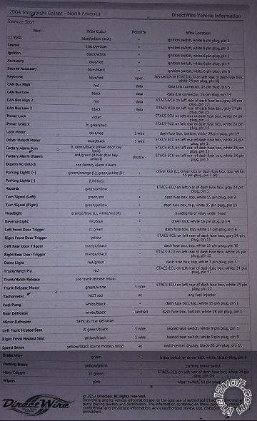
the alarm off. I am noticing that there is a difference in the alarm wiring diagrams from bulldogsecurity and the other sites for parking
lights and door triggers. one site shows a negative wire I can use for parking lights and the option for the 2 positive wires using 2
relays. and the door triggers on one site show I can use 1 wire Red/Green while bulldogsecurity shows I have to use 4 diodes and connect to
all 4 door trigger wires. Do I need a second Ignition wire connected or just leave it not connected? Also the car has a second accessory
wire should I connect a relay to do the second accessory with the first accessory wire or just leave it not connected too? Can anyone help
me figure this out? I really appreciate any assistance. Thank you everyone.
ICMB-7071 Wiring DRAFT for 2004 Mitsubishi Gallant (No transponder Key)
5 Pin Heavy Gauge Harness:
Red - Battery Constant 12v+ Positive Wire (+): Blue/Yellow
Battery Constant 12v+ Positive Wire Location: Ignition Switch Harness
Purple - Starter Positive Wire (+): Black/Yellow
Starter Positive Wire Location: Ignition Switch Harness
Orange - Accessory Positive Wire (+): Blue/Red
Accessory Positive Wire Location: Ignition Switch Harness
Pink A - Ignition Positive Wire (+): Black/White
Ignition Positive Wire Location: Ignition Switch Harness
Pink B - Second Ignition Positive Wire (+): ???
7 Pin Secondary (H4) Harness:
1-3 - Factory wiring to R/S module
4 - Blue/White - N/C
5 - Gray/Black - N/C
6 - BLACK/ White - Chassis Ground
7 - Violet/White - Tachometer Wire Negative Wire (-): Any Wire Not Black/White Or Black
Tachometer Wire Negative Wire Location: At Any Ignition Coil
10 Pin Primary (H1) Harness
1 - Brown - To Siren (+) input
2 - White - Parking Light Positive Wire (+): GREEN/ORANGE (+) and GREEN/WHITE (+) Use BOTH, See NOTE *3 *Requires 2 Relays* Parking Light
Positive Wire Location: In Drivers Kick Panel
Relay 1
Pin 85 - Ground
Pin 86 - 2 - White (+) on Alarm
Pin 87 - GREEN/ORANGE (+)
Pin 87a- N/C
Pin 30 - 12v constant
Relay 2
Pin 85 - Ground
Pin 86 - 2 - White (+) on Alarm
Pin 87 - 12v constant
Pin 87a- N/C
Pin 30 - GREEN/WHITE (+)
3 - Violet - N/C
4 - Blue/Black - Power Door Unlock Negative Wire (-): The left front and left rear door triggers are in a 15 pin plug above the fuses. The
left front door is light green (-) in pin 6, and the left rear door is orange/black (-) in pin 10. The right front and right rear door
triggers are at the ETACS ECU. The right front door is yellow (-) in pin 65, and the right rear door is orange/black (-) in pin 35. When
connecting to an alarm system, use all 4 door trigger wires and diode isolate to connect.
5 - BROWN / Black - Chassis Ground
6 - Violet/Black - N/C
7 - GREEN/ Black - Power Door Lock Negative Wire (-):Light Green/Red
Power Door Lock Negative Wire Location: At ETACS ECU, Pin 34. ETACS (Electronic Timing/Alarm Control System) ECU (Electronic Control Unit)
Is Attached To The Back Of The Fusebox.
8 - WHITE/ Black - Chassis Ground
9 - Red - 12v Constant fused (can tie into heavy gauge red wire from main harness)
10 - Black - Chassis Ground
6 Pin Secondary (H2) Harness:
1 - Orange - Starter kill relay input: Goes to (-) on LED/Scanner bar to enable when alarm is armed
2 - Blue - N/C
3 - WHITE/ Black - N/C
4 - PURPLE / Black - N/C
5 - BLACK/ White - N/C
6 - RED / White - N/C
8 Pin (H3) Harness:
1 - GREEN/ Black - N/C
2 - GREEN / WHITE - N/C
3 - Black - Trunk Pin Switch Negative Wire (-): N/C
4 - Gray - Must add aftermarket hood pin.
5 - Brown - Brake Light Positive Wire (+): Green
Brake Light Positive Wire Location: At Switch Above Brake Pedal
6 - Yellow - Pink wire from main harness
7 - Green - Negative Door Input (-): NOTE *2 THE LEFT FRONT AND LEFT REAR DOOR TRIGGERS ARE IN A 15 PIN PLUG ABOVE THE FUSES. THE LEFT FRONT
DOOR IS LIGHT GREEN(-) IN PIN 6, AND THE LEFT REAR DOOR IS ORANGE/BLACK(-) IN PIN 10. THE RIGHT FRONT AND RIGHT REAR DOOR TRIGGERS ARE AT
THE ETACS ECU. THE RIGHT FRONT DOOR IS YELLOW(-) IN PIN 65, AND THE RIGHT REAR DOOR IS ORANGE/BLACK(-) IN PIN 35. WHEN CONNECTING TO AN
ALARM SYSTEM, USE ALL 4 DOOR TRIGGER WIRES AND DIODE ISOLATE, TO CONNECT, SEE DIAGRAM here
Click for Diagram
8 - Purple - N/C
I noticed something. on this site: https://www.S P A M.com/2004-mitsubishi-galant-auto-alarm-wiring-guide/ they have it different from this site: https://diagrams.marktoonen.nl/index.aspx?MakeID=32&ModelID=17842
I am going with the one from Bulldog site cause they have not steered me wrong in the past but I was wondering if that seems right?
Well, yesterday I installed the alarm/remote start however I couldn't find an easy access place through the firewall so I didn't hookup the siren and hoodpin switch but I also found out that I do have a transponder chip in the key so I will need a transponder bypass. :( Anyone know what would be a good cheap solution for this? I tested the remote start with my key just in the ignition and it worked fine.