2013 Nissan Versa with no immobilizer
Printed From: the12volt.com
Forum Name: Car Security and Convenience
Forum Discription: Car Alarms, Keyless Entries, Remote Starters, Immobilizer Bypasses, Sensors, Door Locks, Window Modules, Heated Mirrors, Heated Seats, etc.
URL: https://www.the12volt.com/installbay/forum_posts.asp?tid=143707
Printed Date: May 16, 2026 at 7:00 AM
Topic: 2013 Nissan Versa with no immobilizer
Posted By: rraider1
Subject: 2013 Nissan Versa with no immobilizer
Date Posted: November 01, 2017 at 4:06 PM
Hi all. I just purchased a 2013 Nissan Versa with no immobilizer, no factory alarm and an aftermarket keyless entry. I'm debating what to install in this car. It seems quite insecure not to have an immobilizer but I guess most thieves aren't running around looking for cheap economy cars to steal  . A couple of years ago I installed Viper systems in my 05 Silverado and 07 Charger with the generous help of this forum so unless there's a good reason not to I'll probable stick with something I can use my current remote on.
I have a spare Viper 4105 but I think I want to add an alarm as well. I'm leaning towards a viper/avital 5305.
Is there any advantage to using a bypass module since I don't need the bypass function? Would it simplify the installation enough to justify the cost? I used iDatalink alca's on the other two vehicles but they both needed the immobilizer bypass.
Key-less entry system is a Code-Alarm CA2051 and was professionally installed when the car was new. I'm guessing this will have to be removed and the door locks connected directly to the new system, possibly with a relay/relays? Currently all doors lock and unlock all together and I'm good with that.
Replies:
Posted By: rraider1
Date Posted: November 06, 2017 at 2:13 PM
Anyone willing to look over my wiring chart for me? Still not sure how to tackle the keyless entry. I think I'm going to go ahead with the 5305 and no bypass.
Not sure how this will post, the spreadsheet can be viewed HERE
5305 Alarm/remote start 2013 Nissan Versa, No factory alarm, no immobilizer
Main Harness, White 5-pin connector
1 BLACK (-) CHASSIS GROUND ground
2 BROWN (+) SIREN OUTPUT siren
3 RED (+) FUSED 12V DC CONSTANT INPUT 12volts pink (40A) + ignition switch, white 6 pin plug, pin 3
4 ORANGE (-) 500mA GWA (GROUND WHEN ARMED) OUTPUT n/a
5 WHITE (+)/(-) SELECTABLE PARKING LIGHT OUTPUT (FUSED) Parking Lights+ red to blue + driver kick, gray 16 pin plug, pin 4
Auxiliary/Shutdown/Trigger Harness, White 24-pin connector
1 PNK/WHITE (-) 200mA IGNITION 2/ACCESSORY OUTPUT n/a
2 BLUE/WHITE (-) 200mA 2ND STATUS /REAR DEFOGGER OUTPUT Green rear defogger switch/HVAC control, black 15 pin plug, pin 10
3 RED/WHITE (-) 200mA TRUNK RELEASE OUTPUT n/a
4 BLACK/YELLOW (-) 200mA DOME LIGHT OUTPUT BLACK 15-PIN PLUG, PIN 8 @ BCM,
5 DARK BLUE (-) 200mA STATUS OUTPUT n/a
6 WHITE/BLACK (-) 200mA AUX 5 OUTPUT n/a
7 WHITE/VIOLET (-) 200mA 2nd UNLOCK OUTPUT ?
8 ORANGE/BLACK (-) 200mA AUX 6 OUTPUT
9 GRAY (-) HOOD PIN INPUT hood pin
10 BLUE (-) TRUNK PIN/INSTANT TRIGGER INPUT trunk pin
11 WHITE/BLUE ** (-) REMOTE START ACTIVATION INPUT n/a
12 VIOLET/WHITE TACHOMETER INPUT
13 BLACK/WHITE* (-) PARKING BRAKE INPUT/EMERGENCY INPUT ground
14 GREEN/BLACK (-) 200mA FACTORY ALARM DISARM OUTPUT n/a
15 GREEN (-) DOOR INPUT lt. blue - BCM above driver kick, white 15 pin plug, pin 7
16 BROWN/BLACK (-) 200mA HORN HONK OUTPUT Horn Trigger red - horn switch, gray 8 pin plug, pin 8
17 PINK (-) 200mA IGNITION 1 OUTPUT n/a
18 VIOLET (+) DOOR INPUT n/a
19 VIOLET/BLACK (-) 200mA AUX 4 OUTPUT n/a
20 BROWN (+) BRAKE SHUTDOWN INPUT lt. green or red, brake switch
21 VIOLET/YELLOW (-) 200mA STARTER OUTPUT n/a
22 GRAY/BLACK (-) DIESEL WTS (WAIT-TO-START) INPUT n/a
23 ORANGE (-) 200mA ACCESSORY OUTPUT n/a
24 GREEN/WHITE (-) 200mA FACTORY ALARM ARM OUTPUT n/a
Remote Start, White 10-pin heavy gauge connector
1 No Connection
2 RED/BLACK (+) FUSED 12V ACCESSORY/STARTER INPUT 12volts pink (40A) + ignition switch, white 6 pin plug, pin 3
3 PINK/BLACK* (+) IGNITION 2/ACCESSORY ISOLATION WIRE # 87A key side (if required) of IGNITION2/ACCESSORY n/a
4 PINK/WHITE (+) IGNITION 2 / ACCESSORY RELAY OUTPUT lt. blue + ignition switch, white 6 pin plug, pin 5
5 RED (+) FUSED 12V IGNITION 1 INPUT 12volts pink (40A) + ignition switch, white 6 pin plug, pin 3
6 GREEN (+) STARTER INPUT (KEY SIDE OF THE STARTER DISABLE) Starter white + ignition switch, white 6 pin plug, pin 2
7 VIOLET (+) STARTER OUTPUT (CAR SIDE OF THE STARTER DISABLE) Starter white + ignition switch, white 6 pin plug, pin 2
8 ORANGE (+) ACCESSORY OUTPUT YELLOW (+) WHITE 6-PIN PLUG, PIN 4 @ IGNITION SWITCH
9 RED/WHITE (+) FUSED 12V IGNITION 2 / FLEX RELAY INPUT 87 12volts pink (40A) + ignition switch, white 6 pin plug, pin 3
10 PINK (+) IGNITION 1 INPUT/OUTPUT Ignition gray + ignition switch, white 6 pin plug, pin 1
Door Lock, White 3-pin connector
1 BLUE (-) 500mA UNLOCK OUTPUT ? third party keyless entry?
2 EMPTY NOT USED
3 GREEN (-) 500mA LOCK OUTPUT ? third party keyless entry?
D2D Harness, Red 4-pin connector
1 BLUE D2D - TX
2 BLACK (-) GROUND
3 GREEN D2d - RX
4 RED (+) 12V
Bitwriter/Directed SmartStart Harness, Black 3-pin connector
1 RED (+) 12V
2 ORANGE ESP 2 - RX/TX
3 BLACK (+) 12V
Posted By: kreg357
Date Posted: November 06, 2017 at 8:58 PM
The Lt Blue Door Pin will only give you the drivers door. To monitor all doors you will need to
connect to all the door trigger wires with diode isolation. Here is the info :
Driver's Front Door Pin LT BLUE (-) BCM WHITE 15 PIN CONN, PIN 7
Pass Front Door Pin PINK (-) BCM WHITE 40 PIN CONN, PIN 12
Driver's Rear Door Pin WHITE (-) BCM WHITE 15 PIN CONN, PIN 8
Pass Rear Door Pin LT GREEN (-) BCM WHITE 40 PIN CONN, PIN 13
Here is the info on the trunk trigger wire :
Trunk Pin PINK (-) BCM WHITE 15 PIN CONN, PIN 2
You will need to test the Defog wire to determine if it's latched or a pulse and program the R/S accordingly.
Domelight Supervision might not be required. Test to see if an Unlock from the aftermarket
RKE system makes the domelight come on.
Remember to program the unit for ACC2 output on the Flex Relay Pink/White wire and set the Parking Light
jumper to (+).
The CA2051 system has built in relays that might be directly controlling the door lock solenoids. If
this is the case, you might need a DEI 451M module to replace it.
Other than that, all you wiring looks fine.
-------------
Soldering is fun!
Posted By: rraider1
Date Posted: November 07, 2017 at 9:14 PM
Thanks!
I went ahead and ordered a 5706v (wiring looks to be pretty much the same as above and it will match what I have in the pickup), a DEI 451M, an iDatalink ALCA, and since I'll now have three DEI systems I ordered a bitwriter as well.
Posted By: howie ll
Date Posted: November 08, 2017 at 6:38 AM
The idatalink part is unnecessary if the vehicle doesn't have an immobiliser, all it will do is save you time and wiring.
-------------
Amateurs assume, don't test and have problems; pros test first. I am not a free install service.
Read the installation manual, do a search here or online for your vehicle wiring before posting.
Posted By: rraider1
Date Posted: November 08, 2017 at 7:15 AM
howie ll wrote:
The idatalink part is unnecessary if the vehicle doesn't have an immobiliser, all it will do is save you time and wiring.
I know, but I have a lot going on at the moment so time is money and in this case worth it for me.
Posted By: howie ll
Date Posted: November 08, 2017 at 7:27 AM
Fair enough.
-------------
Amateurs assume, don't test and have problems; pros test first. I am not a free install service.
Read the installation manual, do a search here or online for your vehicle wiring before posting.
Posted By: rraider1
Date Posted: November 10, 2017 at 5:04 PM
So here is the current keyless entry system. Not sure what the second smaller box is. 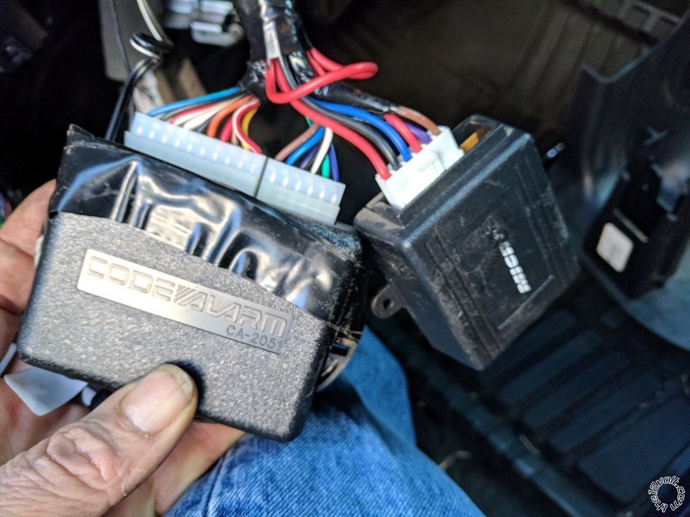
Posted By: rraider1
Date Posted: November 10, 2017 at 6:23 PM
Ok, guess the smaller box is the relays that come with the aftermarket actuators. Tomorrow I'll undo all the tape and hopefully I can figure out how its all wired from there.
Posted By: kreg357
Date Posted: November 10, 2017 at 6:47 PM
Here is a link to the CA-2051 unit :
https://www.voxxelectronics.com/docs/common/CA2051/CA2051_IM.pdf
-------------
Soldering is fun!
Posted By: howie ll
Date Posted: November 10, 2017 at 6:55 PM
Looking at the Code diagram that isn't a lock module unless you can operate the locks from a key in the door in that case the smaller module is the keyless entry, the code is the RF control unit and it should should be wired for NEG lock output,violet and violet black to ground, green/black (lock) and blue/black (unlock) to the smaller module. The idatalink unit won't do the locks use the green (lock) and blue (unlock) from the Viper directly to the original green/black and blue/black going to the smaller module and retain it.
-------------
Amateurs assume, don't test and have problems; pros test first. I am not a free install service.
Read the installation manual, do a search here or online for your vehicle wiring before posting.
Posted By: howie ll
Date Posted: November 10, 2017 at 6:57 PM
Oh bloody heck we crossed paths again!
So what's new AKA great minds etc.
We just repeated each other Kreg!
Almost word for word, how's that for transatlantic cooperation?
-------------
Amateurs assume, don't test and have problems; pros test first. I am not a free install service.
Read the installation manual, do a search here or online for your vehicle wiring before posting.
Posted By: rraider1
Date Posted: November 10, 2017 at 8:40 PM
Thanks Kreg, I found that earlier and grabbed it so I can figure out how it's wired when I untape it all.
If I unlock the drivers door with the key it only unlocks that door. If I use the "manual" lock button on the driver's door it locks all the doors.
Posted By: rraider1
Date Posted: November 10, 2017 at 9:11 PM
While I'm doing this, a solenoid was installed so the trunk can be unlocked by pushing a button on the dash. The solenoid is grounded in the trunk so I assume the trigger is positive. The Viper trunk unlatch is -200ma. Would I need to do a low input to high output relay and then a negative to positive relay to use the viper to unlatch the trunk?
Posted By: howie ll
Date Posted: November 11, 2017 at 4:10 AM
First check the switch! There may be an existing relay, NEVER ASSUME!
Viper red/white to relay 85 20 amps fused 12 volt constant to 86 and 87, 30 to switch out put. 1N4004 diode across 85 and 86,
band to 86.
You're now seeing my point about not bothering with the idatalink part aren't you.
-------------
Amateurs assume, don't test and have problems; pros test first. I am not a free install service.
Read the installation manual, do a search here or online for your vehicle wiring before posting.
Posted By: rraider1
Date Posted: November 11, 2017 at 9:10 AM
I should have explained better. There's a fused positive wire running directly from the fuse box to the switch and then a wire from the switch to the trunk. I'll check the trunk for a relay but I didn't see one when I looked at it previously.
The green/black (lock) and blue/black (unlock) are running from the CA2051 to the smaller module so I'll wire as you instructed above.
Thanks again fr all the help.
Posted By: rraider1
Date Posted: November 11, 2017 at 10:35 AM
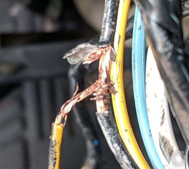
Wow, this is the "professional" shop's connection to the ignition wire on the Code system. No solder, frayed the wire they were tying into, just pathetic. I have the reciept from the install and parts and labor were over $500. I'm sure the rest of their connections will be the same.
Posted By: howie ll
Date Posted: November 11, 2017 at 11:37 AM
Yuk, and wire the trunk solenoid as I explained above.
-------------
Amateurs assume, don't test and have problems; pros test first. I am not a free install service.
Read the installation manual, do a search here or online for your vehicle wiring before posting.
Posted By: rraider1
Date Posted: November 11, 2017 at 1:50 PM
howie ll wrote:
You're now seeing my point about not bothering with the idatalink part aren't you.
Yes, however my least favorite part of doing these is tying into wires at the bcm. I don't know why, it just makes me nervous and the bcm in this car is hard for me to get to. So, the iDatalink module will save me some of that.
Now I'm looking at how to run my wires from the engine bay to the interior and I'm not sure how i'm going to do that. Looks like there's one large bundle of wires in a grommet I can kind of get to. Hopefully I can punch through the side of the grommet without messing anything up.
Posted By: howie ll
Date Posted: November 11, 2017 at 1:55 PM
Stanley knife to cut a slit gently poke a long screwdriver through, WD-40 on the end with some your wires raped securely, that's one method.
Welding rod with a hook to carry the wires is another, done a few of the Euro version, no real problems there.
-------------
Amateurs assume, don't test and have problems; pros test first. I am not a free install service.
Read the installation manual, do a search here or online for your vehicle wiring before posting.
Posted By: rraider1
Date Posted: November 11, 2017 at 6:54 PM
Well either I didn't program it correctly and messed it up or it failed after the first remote start. everything was working fine, alarm triggered, trunk and doors unlocked, and it started with the remote start but almost immediately the horn started beeping, trunk popped open etc, basically everything that was connected except the siren had power and it would no longer respond to the remote. I had to unplug the brain to turn it off and everything is stuck on. If i plug in nothing but the 24 pin connector the trunk pops open, the horn blares ect. If I just plug in the heavy 10 pin connector the car starts and the starter keep running. I double checked all the wires, particularly those on the 10 pin connector and they are correct.
Posted By: howie ll
Date Posted: November 11, 2017 at 6:58 PM
Check your ground, test the voltage between your fuses and ground.
Chuck the idatalink unit and go analogue.
This vehicle is far too simple to make mistakes.
https://www.directechs.com/VehicleCompatibility.aspx?p=-1&v=6554&ps=1&s=0&c=0&pr=-1
-------------
Amateurs assume, don't test and have problems; pros test first. I am not a free install service.
Read the installation manual, do a search here or online for your vehicle wiring before posting.
Posted By: rraider1
Date Posted: November 11, 2017 at 8:03 PM
I'm not sure I made a mistake although it wouldn't be the first time. Have you ever seen a Viper without a remote start shutoff switch and no where to plug one in? I'm kind of wondering if I got a knock-off unit. Anyway the Viper unit is toast. It's hung with everything on and won't take any input from the control station or the remote. Even after unplugging everything, as soon as I plug something in it sends power to whatever I plug in.
Posted By: rraider1
Date Posted: November 11, 2017 at 8:42 PM
Tested ground and it's good. Voltage at fuses is 12.13v.
Posted By: howie ll
Date Posted: November 12, 2017 at 2:14 AM
Disconnect idatalink unit.
I've never seen a faulty Viper unit.
-------------
Amateurs assume, don't test and have problems; pros test first. I am not a free install service.
Read the installation manual, do a search here or online for your vehicle wiring before posting.
Posted By: rraider1
Date Posted: November 12, 2017 at 8:05 AM
I removed the iDatalink after it happened to eliminate it from the equation.
Posted By: rraider1
Date Posted: November 12, 2017 at 8:47 AM
Ok, just went back out to confirm but if I just connect the six pin connector the parking lights come on and the siren is energized. I don't have the siren grounded yet, that's why i wasn't hearing it. It's like every circuit in the Viper is stuck open.
Posted By: rraider1
Date Posted: November 12, 2017 at 8:52 AM
Correction, I should have said every circuit is stuck "on" instead of open.
Posted By: rraider1
Date Posted: November 12, 2017 at 10:28 AM
Looks like the same thing happened to someone else in February... https://www.the12volt.com/installbay/forum_posts.asp?tid=142481
Posted By: rraider1
Date Posted: November 17, 2017 at 10:30 AM
Just to update this post, I replaced the "brain" with a new one, plugged it in without changing anything and programmed it with the bitwriter. It works perfectly.
Thanks again Howie and Kreg for your help!
|
 . A couple of years ago I installed Viper systems in my 05 Silverado and 07 Charger with the generous help of this forum so unless there's a good reason not to I'll probable stick with something I can use my current remote on.
