Where does this wire go? viper ign in/out
Printed From: the12volt.com
Forum Name: Car Security and Convenience
Forum Discription: Car Alarms, Keyless Entries, Remote Starters, Immobilizer Bypasses, Sensors, Door Locks, Window Modules, Heated Mirrors, Heated Seats, etc.
URL: https://www.the12volt.com/installbay/forum_posts.asp?tid=143708
Printed Date: May 16, 2026 at 8:02 AM
Topic: Where does this wire go? viper ign in/out
Posted By: spadz93
Subject: Where does this wire go? viper ign in/out
Date Posted: November 01, 2017 at 4:24 PM
Quick backstory: I tried instaling this remote start in a 5th gen camaro, couldn't figure it out, so I had a shop do it. Later, I traded that car in for *another* 5th gen camaro, and want to put the kit into this car. Wiring should be the exact same. I looked at the wiring diagrams and the harness of the kit itself to figure out what wires were used and which were not. Unfortunately I was rushing when removing the kit, so I didn't document where what was connected. I've narrowed down all the connections otherwise, except for one wire.
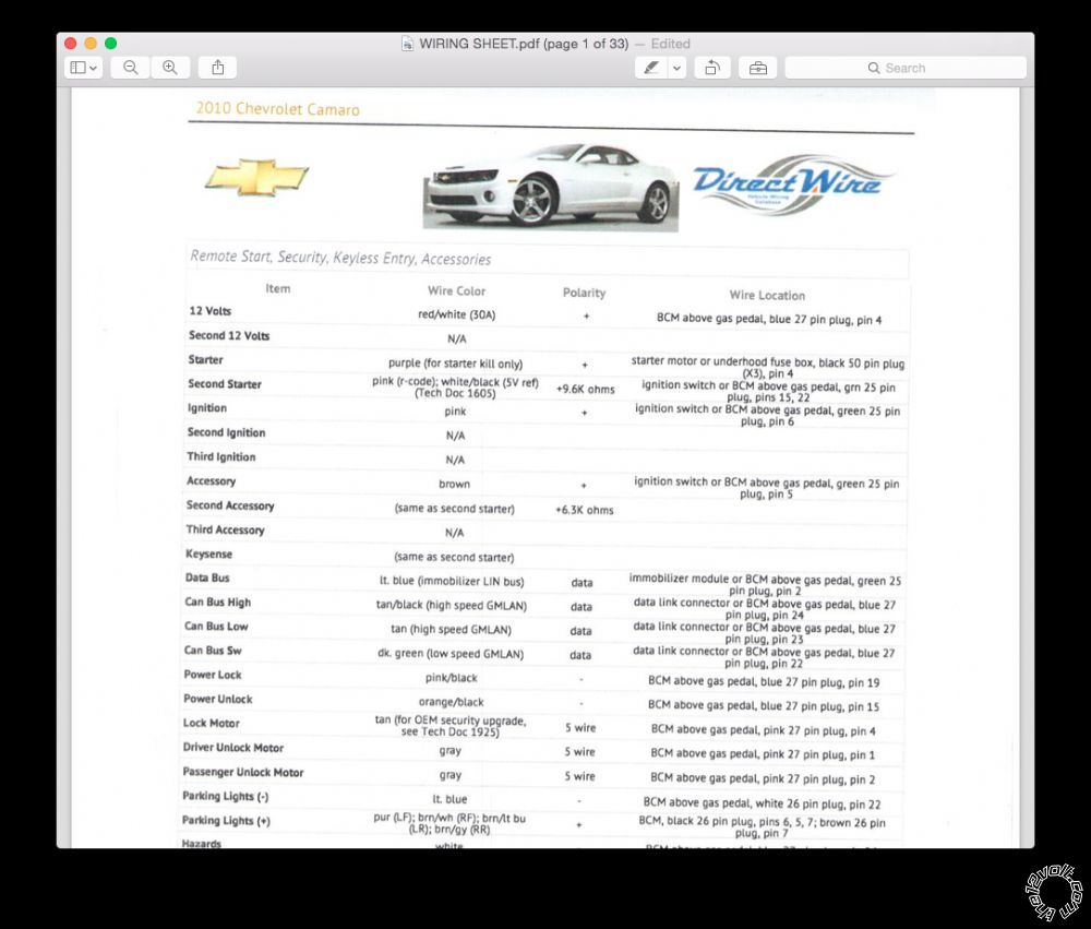
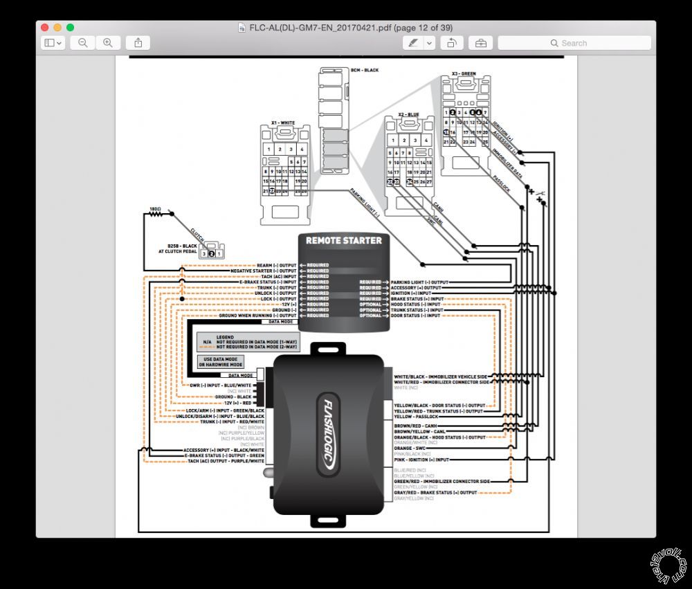
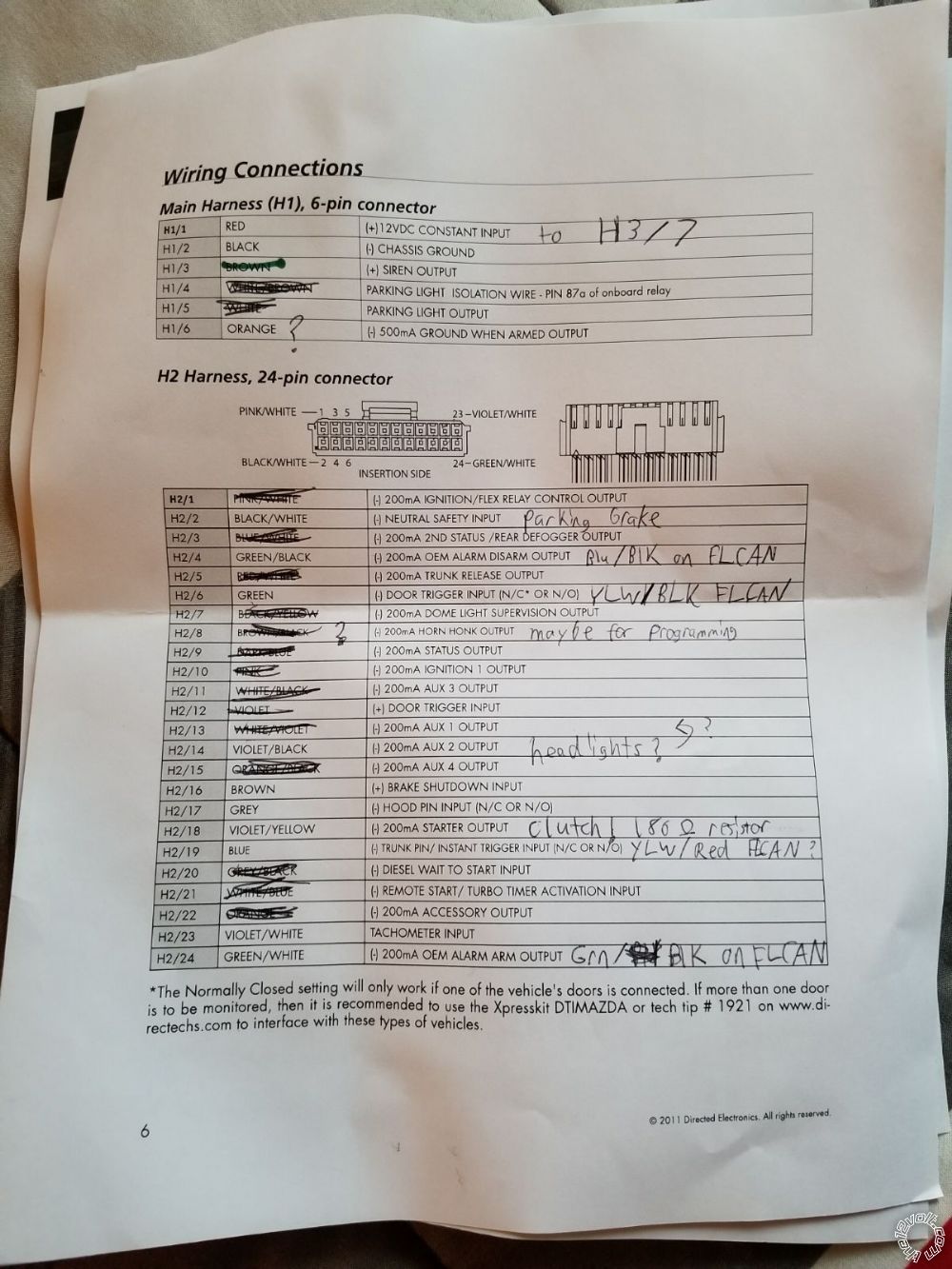
The wire in question on my viper kit is labeled (1) IGNITION 1 INPUT/OUTPUT. It's a pink wire coming from harness 3 (10 pin) if that helps any. It has a connector on the end of it, but looking at the wiring diagrams, there appears to not be any place for this wire to go. My only guess is it's supposed to go to pin 22 on the GREEN BCM connector, labeled as Second Starter, but that's only a 5V reference point. Attached is a printout of most of the ignition/security wires, as well as the diagram for my flashlogic that i'll be using,
as well as some of my notes indicating which wires were tied off/not used.
.jpg)
Replies:
Posted By: rraider1
Date Posted: November 01, 2017 at 4:42 PM
Just a novice myself so you might want confirmation, but your sheet says ignition switch or pin 6 on the green 25 pin plug at the BCM.
Posted By: rraider1
Date Posted: November 01, 2017 at 4:47 PM
If you look at the diagram in the second picture it shows the same thing, pin 6 on the green connector along with the pink ignition input of the flashlogic.
Posted By: spadz93
Date Posted: November 01, 2017 at 4:57 PM
On harness three, you'll see i bridged three wires together. This was done for whatever reason by the installer, but it worked. I thought that went to the ignition pin 6, rather than the wire in question (H3/1)
Posted By: rraider1
Date Posted: November 01, 2017 at 5:20 PM
The three that are bridged together on harness 3 are your 12v constant input.
Posted By: spadz93
Date Posted: November 01, 2017 at 5:23 PM
i have to look again, but for whatever reason my h1/1 12v constant was tapped into h3/7 but that wire wasnt used.... Maybe the three bundled wires go to the 12v constant and then h3/1 goes to ignition?
Posted By: rraider1
Date Posted: November 01, 2017 at 5:36 PM
The three bundled wires are 12v inputs for the built in relays, You are saying they ran the power to the system from one of the relay outputs. I don't have a clue why they did that, probably time for me to sit back and learn....
Posted By: spadz93
Date Posted: November 01, 2017 at 5:39 PM
I haven't the slightest clue if that's actually what happened, purely speculating
Posted By: spadz93
Date Posted: November 01, 2017 at 5:46 PM
I'm re-reading the sheet and just seeing the little afternote where it says 12v input on each of those bundled wires. Good thing, so that's definitely a rock solid 12v constant input. Now, explaining the tap to the un-used wire. I see that pin H3/2 gets thrown into the 12v constant bundle. Thinking maybe that pin touches to the H1/1 wire and supplies constant 12v? That would leave the originally mentioned pin H3/1 free to touch the ignition wire at the BCM, green pack pin 6
|