Astrostart Module Replacement Programing
Printed From: the12volt.com
Forum Name: Car Security and Convenience
Forum Discription: Car Alarms, Keyless Entries, Remote Starters, Immobilizer Bypasses, Sensors, Door Locks, Window Modules, Heated Mirrors, Heated Seats, etc.
URL: https://www.the12volt.com/installbay/forum_posts.asp?tid=144172
Printed Date: May 13, 2026 at 3:59 PM
Topic: Astrostart Module Replacement Programing
Posted By: lemoncadillac
Subject: Astrostart Module Replacement Programing
Date Posted: February 21, 2018 at 4:55 PM
Hi
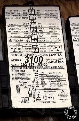
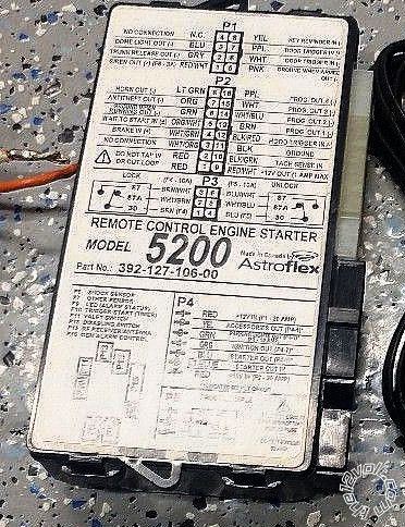
New here. I have searched and can not find my answer. I have a 2004 GMC Yukon XL 1500. It has had the Astrostart 3100 alarm/start system since day 1. Long story short the dealer fried the 3100 module. I replaced it with a 5200. I believe it will work. All the wiring was a direct plug and play. I have programed the remotes. Doors unlock and lock. I can not get the auto start to work. I get a constant flash of the led when trying to program the tach learning. Any help would be helpful.
Thank you in advance
Replies:
Posted By: lemoncadillac
Date Posted: February 21, 2018 at 5:45 PM
Update
I am now getting a 4 flash code when start fails. No wiring changes. If the wiring is fine. When I set 1,5,6,7 it clicks 4 times,seconds then goes to a continual flash.
Posted By: monty_77
Date Posted: February 27, 2018 at 8:08 PM
Ok how do you hav it wired and I can walk you through programming, I am assuming that when you say 5200 you mean ether athe 5224 or the 5225 one mile remote starter. Both should have a e-xrt on the brain. I. Will also need to now what bypass you are using. My guess for the year it is most likely a one for the passlock2 and another for the door locks through data.
Please note that I would like to know the wiring and how it hooked up because you should have two outputs to ignition and two to accessory for that vehicle, so you dont have transmission problems
Code 4 is not tach reading
Posted By: lemoncadillac
Date Posted: February 27, 2018 at 8:42 PM
It was professionally installed in 2004. It had a 3100 module. I brought the vehicle in for service work. When it returned the autostart did not work. I took it to where it was installed and they told me the module was fried. I confirmed this. I replaced the module with a 5200. Programmed the remotes. No start. Did the 1,5,6,7 key in warmed up brake sequence. The module seems to accept the code but flashes continuously. When trying to start code 4 flashes no start. Everything has worked for 14 years no wiring changes. The alarm, door locks and start. Now doors look, alarm works, no start.
Posted By: monty_77
Date Posted: February 27, 2018 at 9:07 PM
The new module will still need to be programmed to do outputs correctly they are not plug and play for vehicles, I just need to know what wire colors of the remote start are hooked to the wire colors of the vehicle and I can help, and just so you know the led will flash all the time with engine running, it is letting you know it is seeing a tach, it should not be really fast or really slow,
I am going to guess that they used a negative out put for the park lights and the park lights wire reprogrammed for the ignition so if this wire is not right it will not feed the ignition wire during remote start and will not start
Posted By: monty_77
Date Posted: February 27, 2018 at 9:13 PM
Ok after looking up the manual for the brain, the park light is not programmable like later models so some programmable out put will have to be use, so I will need to know what wire
S go where to help you program it to this vehicle.
Posted By: lemoncadillac
Date Posted: February 27, 2018 at 9:17 PM
I will take pictures tomorrow and post them. Thank you
Posted By: monty_77
Date Posted: February 27, 2018 at 9:19 PM
I will pm you and send email, might make it easier.
Posted By: lemoncadillac
Date Posted: February 27, 2018 at 9:25 PM
DIRECTWIRE WIRING INFORMATION - GMC / YUKON / 2004 / Remote Start
12volts red & RED / white + ignition harness
Starter yellow + ignition harness
Second Starter N/A
Ignition pink + ignition harness
Second Ignition white + ignition harness
Notes: To avoid the check engine light from coming on and possible damage to the automatic transmission, the second ignition in this vehicle MUST be powered when adding a remote start system.
Third Ignition N/A
Accessory orange + ignition harness
Second Accessory brown + ignition harness
Keysense lt. green - ignition harness
Power Lock use Directed module 456G
Notes: If Directed module 456G is not available, refer to DirectFax document 1601. Upper trim level vehicles may have a door lock switch on the right rear panel. If present use white (-) for lock and lt. blue (-) for unlock.
Power Unlock see power lock
Lock Motor gray driver door module in door
Unlock Motor tan driver door module in door
Parking Lights+ brown + driver kick panel
Parking Lights- gray/black - switch or BCM, brown plug, pin B2
Notes: The BCM (Body Control Module) is under the driver side dash. It has 6 plugs in it, the purple plug is on the back.
Hazards white - steering column
Turn Signal(L) green + steering column
Turn Signal(R) lt. green + steering column
Reverse Light lt. green + BCM, black plug, pin F
Notes: The BCM (Body Control Module) is under the driver side dash. It has 6 plugs in it, the purple plug is on the back.
Door Trigger see notes - see notes
Notes: The driver door trigger is gray/black at the driver door module in the door. The RF door trigger is BLACK/ white at the passenger door module in the door. The LR door trigger is lt. blue/black, pin A3, and the RR is lt. GREEN/ black, pin A2, they are in the purple plug at the BCM. Use all four wires and diode isolate each.
The BCM (Body Control Module) is under the driver side dash. It has 6 plugs in it, the purple plug is on the back.
Dome Supervision gray/black + BCM, black plug, pin E
Notes: The BCM (Body Control Module) is under the driver side dash. It has 6 plugs in it, the purple plug is on the back.
Trunk/Hatch Pin pink/black - BCM, purple plug, pin A1
Notes: The BCM (Body Control Module) is under the driver side dash. It has 6 plugs in it, the purple plug is on the back.
Hood Pin N/A
Trunk/Hatch Release N/A
Power Sliding Door N/A
Factory Alarm Arm arms with lock
Factory Alarm Disarm lt. green - driver door module in door
Disarm No Unlock see factory alarm disarm
Tachometer white ac instrument cluster, pin A5 or PCM
Notes: The PCM (Powertrain Control Module) is in the left front of the engine compartment to the left of the fan shroud. The tach wire is in the green plug, pin 10.
For tach can also go to any of the ignition coils or injectors and use the wire that is NOT pink, black, or brown.
Wait to start N/A
Brake Wire white + brake pedal switch
Parking Brake lt. blue - switch or BCM, lt. blu plug, pin A7
Notes: The BCM (Body Control Module) is under the driver side dash. It has 6 plugs in it, the purple plug is on the back.
Horn Trigger BLACK / YELLOW to black - column or BCM, gray plug, pin B9
Notes: The BCM (Body Control Module) is under the driver side dash. It has 6 plugs in it, the purple plug is on the back.
Memory Seat 1 red + driver door module in door
Memory Seat 2 pink + driver door module in door
Memory Seat 3 N/A +
Immobilizer Bypass Module: Required: Yes Type: Passlock 2 Part #: 555L or 555T
Notes: The Passlock 2 wire colors are yellow, black (org/blk), and RED / white (not used).
I will verify tomorrow with pics.
Posted By: monty_77
Date Posted: February 27, 2018 at 10:51 PM
I have the wiring for you vehicle I just need the verification from remote start to the vehicle, match the remote colors to what vehicle colors they are attatted to, just need to know what wires they used for what, and I would guess they most likely got the tach from behind the instrument cluster it was easier then under the hood.
Posted By: lemoncadillac
Date Posted: February 28, 2018 at 5:18 PM
Posted By: lemoncadillac
Date Posted: February 28, 2018 at 5:30 PM
Please look at P5. I may not have switched these wires correctly.
P5: PROGRAMMABLE RELAY
This is a three-pin connector connected to an internal standard automotive style relay, i.e. COMMON-30, N.O.
(normally open)-87 and N.C. (normally closed)-87A.This connector is there to save an external relay in your
installation. The installation of this relay requires a maximum of 3 wires. Refer to Stage 1 - Level 9 on page 20 for
more details about the options available on this output.
Cut to White wire supplied in the box for the wiring of this output.
Posted By: monty_77
Date Posted: February 28, 2018 at 6:46 PM
The picture did not show will look on my computer in a bit or I sent you my email pm and you gcould email them to me
Posted By: lemoncadillac
Date Posted: February 28, 2018 at 6:56 PM
Posted By: monty_77
Date Posted: February 28, 2018 at 11:37 PM
Wires on programmable relay look go, I usually put the constant 12volt to pin 87 and output to 30 common, so your pin 87a is not hot when not running, doesnt matter ether way will still work the same,
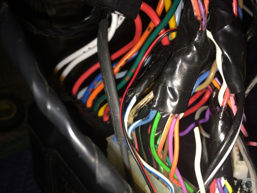
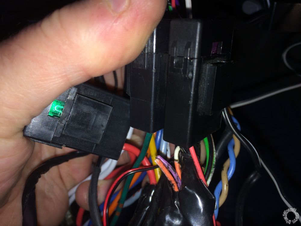
What I was looking for was off the remote start on P2 harness where the white/blue, brown, white, and violet outputs where hooked to you vehicle? And the color wire it is attached to. Theses are four programmable outputs
I will all so need to know what color the white white in P5 is hooked to in vehicle as in color of wire on vehicle
If I had to just guess at programming for you this is what it would be with out knowing what the programmable outputs are hooked to
Do this with engine not running, key not in ignition, I will give you a set of dip switches that need to be on and after setting them you will push on brake and led should flash the number for the level to confirm programming and then move to the next one and so on.
Please note that I did not include setting for alarm features in this they can be changed later lets just get it to start first
Level 2
Dip switch 1 and 6 on all others off, push brake led on brain should flash 2 times
Please note that I do not know what the programmable outputs are doing so I will not have you change level 5,6,7,or 8 with out more information
Level 9
Dip switches 1,4,7,8 on all others off and push brake led should flash 9 times
Level 12
Dip switches 3,4,8 on all others off push brake led should flash 12 times, this will give you the longest runtime
Move all dip switches to off and hit brake one more time
You can try to remote start make sure shut off switch is on
This is the best I can do with out knowing what starter wires are attached to what color wires on the vehicle, if I get the right ones we can talk about a alarm setting too,
Example starter wire p4 dark blue is connected to vehicle wire yellow, I can figure it out from there
,
Posted By: lemoncadillac
Date Posted: February 28, 2018 at 11:57 PM
You are my hero!!!! It started and is running now.
Posted By: lemoncadillac
Date Posted: March 01, 2018 at 12:30 AM
starter wire p4 dark blue is connected to vehicle wire yellow,confirmed YES
Posted By: lemoncadillac
Date Posted: March 01, 2018 at 4:45 PM
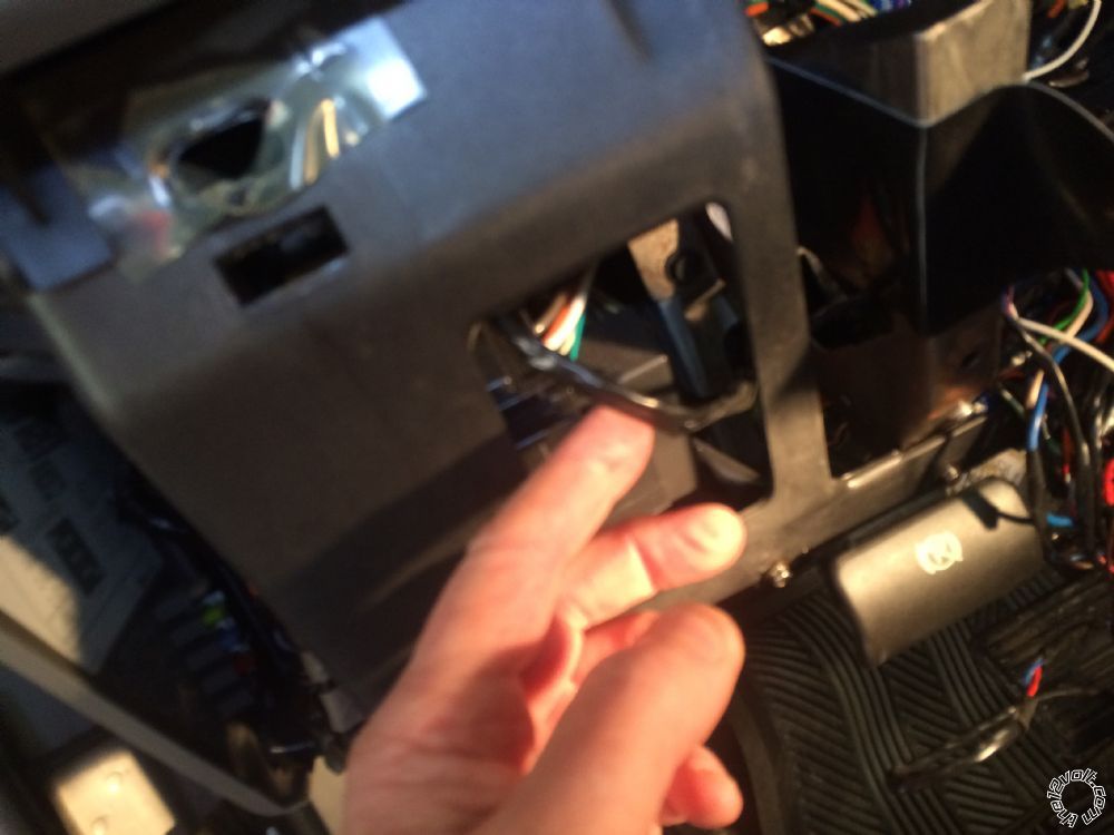
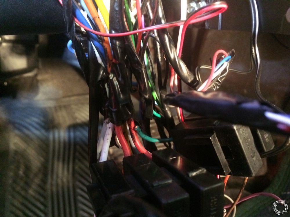
P2 white/blue. Go up in the dash. See pic. Others cut see pics.
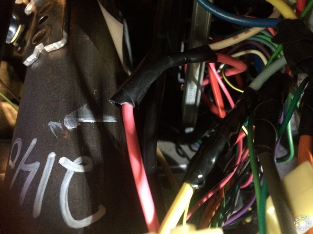
P5. 1 white ties into pink
Other white fused and then ties into red
I will attach pics once I am back in the house
Posted By: lemoncadillac
Date Posted: March 01, 2018 at 5:28 PM
|
.jpg)
.jpg)
.jpg)
.jpg)
.jpg)
.jpg)
.jpg)
.jpg)
.jpg)
.jpg)
.jpg)
.jpg)