2018 Toyota Sienna LE Keypad Install
Printed From: the12volt.com
Forum Name: Car Security and Convenience
Forum Discription: Car Alarms, Keyless Entries, Remote Starters, Immobilizer Bypasses, Sensors, Door Locks, Window Modules, Heated Mirrors, Heated Seats, etc.
URL: https://www.the12volt.com/installbay/forum_posts.asp?tid=144176
Printed Date: May 13, 2026 at 12:26 PM
Topic: 2018 Toyota Sienna LE Keypad Install
Posted By: jangelj
Subject: 2018 Toyota Sienna LE Keypad Install
Date Posted: February 23, 2018 at 10:45 AM
I am looking to install a keypad on my 2018 Toyota Sienna LE (with key...NOT push button start). The one I have is similar to this one:
https://www.amazon.com/Accele-RS505-Numeric-Touchpad-Keyless/dp/B01IDX2EO0/ref=sr_1_4?ie=UTF8&qid=1519403804&sr=8-4&keywords=car+keypad&dpID=41qro0Bp58L&preST=_SY300_QL70_&dpSrc=srch
Can anyone help me out with a wiring diagram for my vehicle? I'm thinking I just need POS, NEG, Door Unlock, door lock and alarm disarm wires?
There are instructions for the keypad here (not my post, but has a picture of install page).
https://www.tacomaworld.com/threads/accele-rs505-keyless-entry-install.347288/
Does anyone know if the 2018 wiring is the same as the 2017 model? Maybe I can refer to 2017 diagram, if I can find one.
Thanks for any help!
-------------
thanks!
Replies:
Posted By: l_walker
Date Posted: March 28, 2018 at 8:36 AM
Did you ever find out how to do this? I just ordered the same kit.
Posted By: kreg357
Date Posted: March 28, 2018 at 8:42 PM
What exact Year, Make and Model are you planning to install this in?
-------------
Soldering is fun!
Posted By: l_walker
Date Posted: March 29, 2018 at 8:13 AM
2018 Toyota Sienna LE FWD
Posted By: kreg357
Date Posted: March 29, 2018 at 8:00 PM
I can't find any solid info on the 2018 Sienna but it appears to be similar to the 2017 model
in most areas. The following info is good for a 2017 so you must locate, test and verify it on
a 2018. As far as I know, the Sienna LE model does not have a Factory Alarm or power Rear Hatch.
Constant 12 volts WHITE (140A) DRIVER DASH FUSE BOX WHITE 1 PIN CONN or thick Red @ Ignition Switch Plug, middle pin *
Parking Lamp (+) GREEN (+) @ DRIVER DASH FUSE BOX
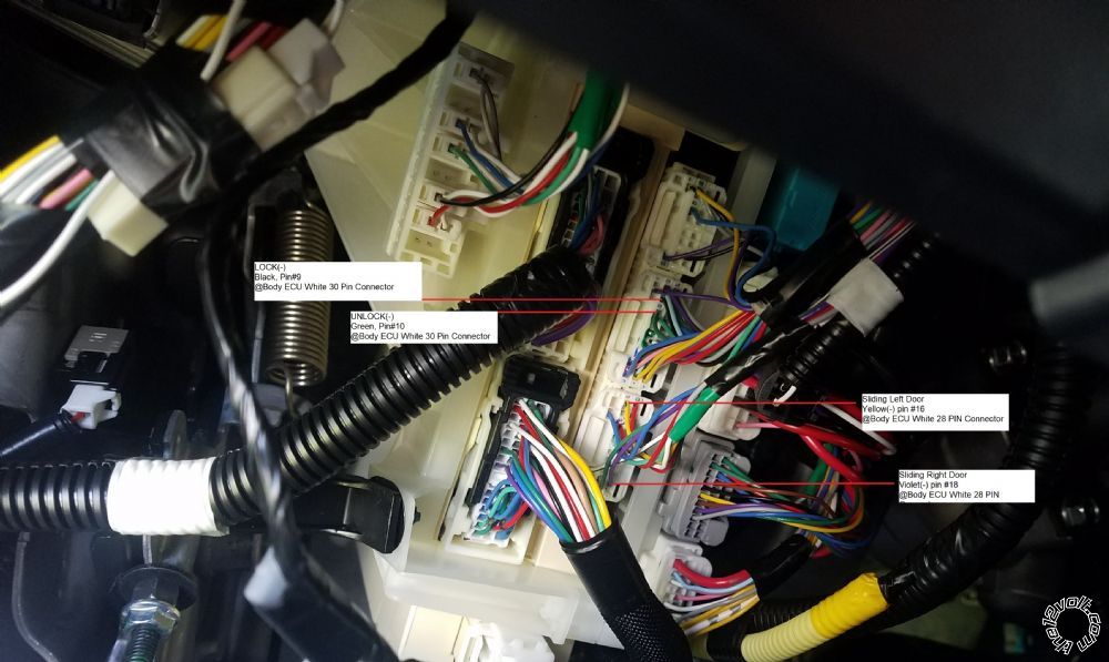
Lock BLACK (-) @ BODY ECU WHITE 30 PIN CONN, PIN 9
Unlock GREEN (-) @ BODY ECU WHITE 30 PIN CONN, PIN 10
Pwr Sliding Door Left YELLOW (-) @ BODY ECU - WHITE 28 PIN CONNECTOR PIN 16 *
Pwr Sliding Door Right VIOLET (-) @ BODY ECU - WHITE 28 PIN CONN, PIN 18 *
* Verified on 2018 model.
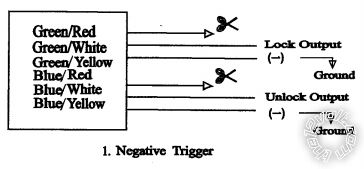
ADD ON unit wiring.
Green/White to Chassis Ground
Green/Yellow to (-) Lock
Blue/White to Chassis Ground
Blue/Yellow to (-) Unlock
Black to Chassis Ground
Red to either +12V Constant listed above
Yellow to (+) Parking Light
Purple to Sliding Door
Yellow/Black to other Sliding Door
-------------
Soldering is fun!
Posted By: l_walker
Date Posted: April 22, 2018 at 2:45 PM
This works! You Rock!
The only thing I can't figure out is the Parking Lamp. You said:
Parking Lamp (+) GREEN (+) @ DRIVER DASH FUSE BOX
But, for the life of me, I cannot figure out where that is. I don't see a distinct green wire going into the driver's fuse box. I took a few pics of the area:
https://imgur.com/a/vyXtGVw
(I also included some snapshots of the EWD for the "Turn Signal and Hazard Warning Light" from TIS for the 2018. Dunno if that helps.)
Posted By: kreg357
Date Posted: April 22, 2018 at 6:19 PM
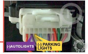
Most installers use the (-) Parking Light wire. The (-) Parking Light wire is very easy to find at the Headlight switch
connector. Your PKE unit only supplies (+) Parking Light outputs but you can get around that if you want. All that is
needed is a SPDT relay to convert the (+) Parking Light output to a (-) signal. Here is the info :
PARKING LIGHTS ( - ) YELLOW (-) @ Headlight connector, Pin 18 of 20.
Photo of headlight switch plug.
You can test for this wire by using a Digital Multi Meter set to 20V DC. Connect the Red lead to +12V constant
and connect the Black lead to the suspect Yellow wire. With the switch in the OFF position you will read 0V. With
the switch set to Parking Lights you will read +12V. Here is the relay wiring :
Relay Pin 86 to either Yellow (+) Parking Light output wire from PKE unit
Relay Pin 85 to Chassis Ground
Relay Pin 87 to Chassis Ground through 2 amp fuse
Relay Pin 30 to Yellow (-) Parking Light wire at Sienna Headlight switch connector
Relay Pin 87a - not used - insulate
I use mini-relays rated at 10 amps for this type circuit. They can be found on EBay for around $1 but require
some soldering to add the needed wires.
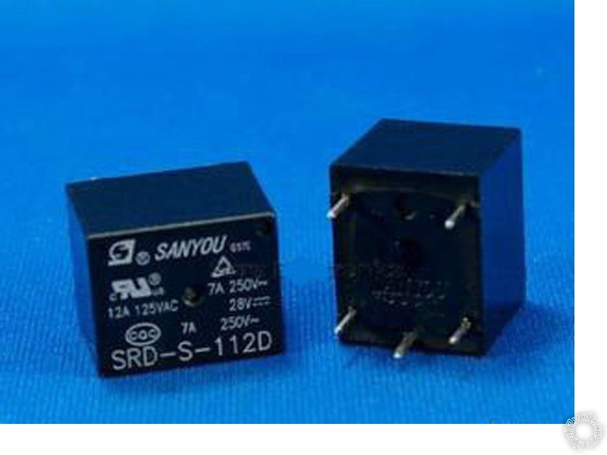
If you want a mini relay that comes pre-wired, look for a Directed
8616. You can also use the larger 30/40 Amp relays. ------------- Soldering is fun!
Posted By: kreg357
Date Posted: April 22, 2018 at 6:28 PM
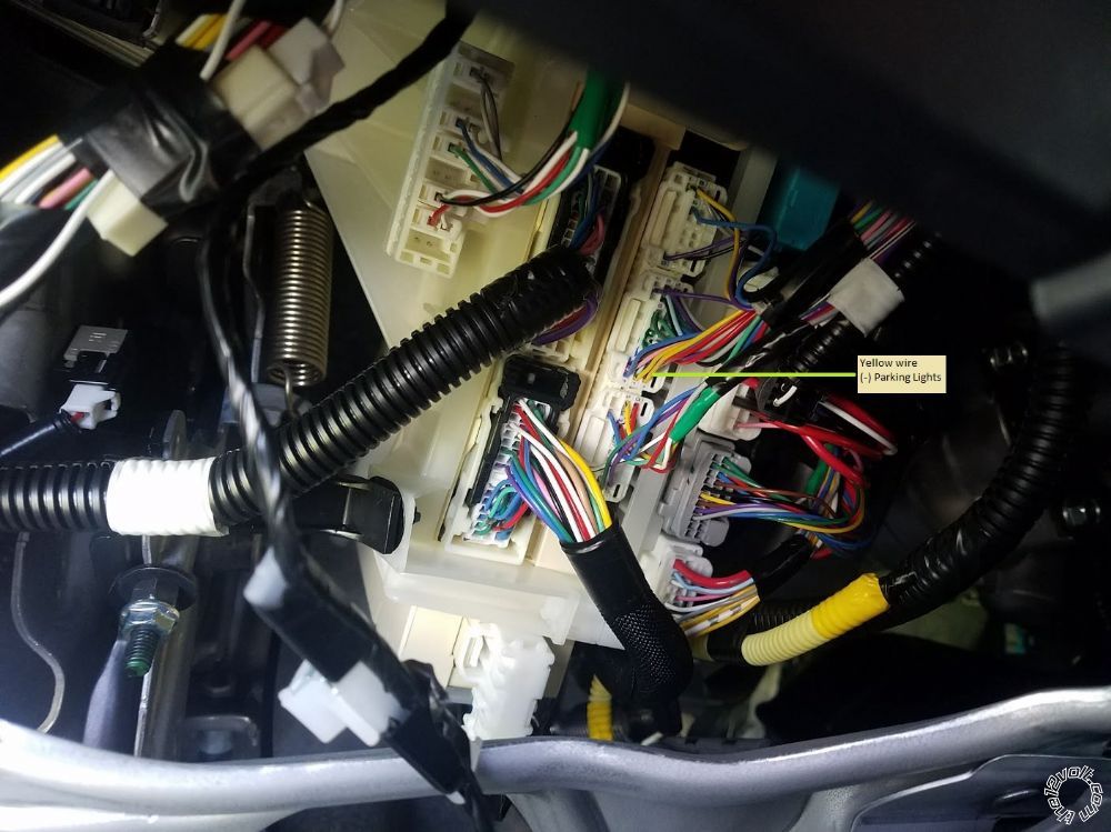
I'd also be willing to bet that you could get the (-) Parking Lights at the Body ECU.
It should be the Yellow wire indicated in your revised photo below :
 ------------- Soldering is fun!
Posted By: l_walker
Date Posted: April 23, 2018 at 8:39 AM
Cool. Thanks!
Also, if anyone else is looking at this. Here are the other connections that worked for me
Posted By: jangelj
Date Posted: April 23, 2018 at 7:02 PM
Thanks for sharing. I still have not ordered my keypad. But I'm curious what you needed the 2 sliding door wires for?
-------------
thanks!
Posted By: l_walker
Date Posted: April 23, 2018 at 7:17 PM
jangelj wrote:
I'm curious what you needed the 2 sliding door wires for?
You certainly don't need them. But, it does allow you to open/close the sliding doors with the keypad.
Door Unlock: PIN + 1/2 button
Door Lock: PIN + 3/4 button
Left Sliding door: PIN + 5/6 button
Right Sliding door: PIN + 7/8 button.
The parking lights are actually a little more useful as they are used to blink in order to indicate success/failure codes. But, even that is only during programming.
(My LE doesn't have power tailgate, but that's also available. )
Posted By: jangelj
Date Posted: April 23, 2018 at 8:11 PM
I didn't realize you could open the rear doors. Great! Also, is it true that there is no alarm or security wire to connect?
So the minimum wires you could connect to make this function is -, + lock and unlock
-------------
thanks!
Posted By: l_walker
Date Posted: April 23, 2018 at 9:26 PM
jangelj wrote:
I didn't realize you could open the rear doors. Great!
I just wish you could unlock the doors and open a side door without entering the PIN twice. On my old Ford, you could enter the PIN once and then do multiple operations. On this thing, unlocking the doors and opening a side door takes 12 button presses (my PIN is 5 digits).
jangelj wrote:
Also, is it true that there is no alarm or security wire to connect?
So the minimum wires you could connect to make this function is -, + lock and unlock
Yes. And, technically, you don't even need lock. So, you could just hook up Unlock, the Unlock ground, 12v constant power and its ground.
BTW, I used and recommend Posi-Taps. At close to $2 a tap, they're pretty pricey, but they made it soo easy. I don't care what kreg357 says, soldering a tap into a 30 pin connector is not my idea of fun.
Posted By: l_walker
Date Posted: April 25, 2018 at 7:25 PM
I was wrong! This does not work if I lock the doors with the keyfob.
If I lock the doors with the keypad or the lock button on the door, it does work. So, maybe there is some sort of security wire you have to connect. The keyfob does make chirps whereas the other unlock/lock methods do not.
Posted By: geepherder
Date Posted: April 25, 2018 at 8:15 PM
See if pulsing the keysense wire first will work.
-------------
My ex once told me I have a perfect face for radio.
Posted By: jangelj
Date Posted: April 25, 2018 at 8:38 PM
Thanks for the clarification on it not working when locked with the fob. That is important. Please post back if the key sense wire works. I likely will not have an opportunity install mine for a few weeks.
-------------
thanks!
Posted By: l_walker
Date Posted: April 25, 2018 at 8:57 PM
I'll need some help locating the key sense wire. Oh, and what would I hook that up to? The unlock wire?
Posted By: kreg357
Date Posted: April 26, 2018 at 6:16 AM
The Keysense wire can be found at the ignition switch as shown below :
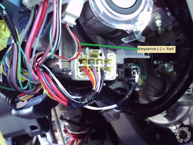
Additional possible locations :
Bulldog Security :
KEYSENSE RED (-) @ DASH FUSE BOX @ ECU WHITE 40 PIN PLUG, PIN 17
Omega :
Keysense RED (-) BODY ECU WHITE 30 PIN CONN, PIN 17
Same DMM setup and test procedure as listed above for (-) type signals.
------------- Soldering is fun!
Posted By: l_walker
Date Posted: April 26, 2018 at 8:43 AM
Ah, thanks. But, uh, what do I connect the KeySense to on the ADD ON unit?
Here's a snapshot of the wiring diagram just in case: https://i.imgur.com/J7XuoV8.png
BTW, you said:
kreg357 wrote:
ADD ON unit wiring.
Green/White to Chassis Ground
Green/Yellow to (-) Lock
Blue/White to Chassis Ground
Blue/Yellow to (-) Unlock
Black to Chassis Ground
But, the wiring diagrams seems to show Green/Yellow and Blue/Yellow going to ground. Does that matter?
Posted By: kreg357
Date Posted: April 26, 2018 at 2:09 PM
Good question. Never tried installing a system like your add-on unit, plus I always use a
full featured DATA style bypass module on these newer Toyotas that handles the locks and
alarm system.
From your description of the problem, it only happens when you lock the van with the factory
FOB. You need to do some testing to see what is going on. I'm pretty sure your van does not
have a Factory Ararm system but you should test to ensure it does not have the alarm.
The next test would be to see if the passenger door lock buttons get "turned off" by the van
after a lock command from the factory FOB. Your add-on system is sending an unlock command to
the actual wire coming from the door button so the button should be in-op, too. There could be
a few seconds delay, perhaps a full minute before the interior door locks become in-operative
after a FOB lock. So, lock with the FOB, wait a minute and try the interior door unlock buttons.
The next test would be to see if a Keysense signal would awaken the passenger door unlock button.
Easy enough to do, just lock with the FOB, wait a minute and insert the key into the ignition switch
and then remove it and try the unlock button. If that worked, then you would need to find a way
to get your add-on system to do the same thing. The only signal you could use would be the same
Unlock output you have already connected to the vans unlock wire. Here you would need to split
and diode isolate the Unlock output wire and connect to the Keysense wire listed above in addition
to the unlock wire.
-------------
Soldering is fun!
Posted By: kreg357
Date Posted: April 26, 2018 at 2:18 PM
l_walker wrote:
Ah, thanks. But, uh, what do I connect the KeySense to on the ADD ON unit?
Here's a snapshot of the wiring diagram just in case: https://i.imgur.com/J7XuoV8.png
BTW, you said:
kreg357 wrote:
ADD ON unit wiring.
Green/White to Chassis Ground
Green/Yellow to (-) Lock
Blue/White to Chassis Ground
Blue/Yellow to (-) Unlock
Black to Chassis Ground
But, the wiring diagrams seems to show Green/Yellow and Blue/Yellow going to ground. Does that matter?
Sorry for the confusion on the lock relay wiring. I followed the Tacoma world info. However it doesn't
make too much difference. We are only using relay Pins 30 and 87 of the internal relays so it doesn't
matter if 87 is the output instead of Pin 30. The ground signal still gets passed through when energized.
Pin 87a is not used and should be cut / insulated. ------------- Soldering is fun!
Posted By: l_walker
Date Posted: April 26, 2018 at 3:11 PM
Thanks so much for replying!
1) There's no real alarm. I can lock the car with the keyfob, wait a few minutes and then open the door and nothing happens.
2) The passenger side door lock button definitely is disabled after locking with the keyfob.
3) Just putting the key in the ignition and removing it doesn't re-activate the passenger door lock button. I have to turn the key to the ON position (Accessory position doesn't do it) before the unlock button is activated. Given that, is keysense wire likely to work?
Posted By: kreg357
Date Posted: April 26, 2018 at 4:35 PM
Good info.
1. Definitely no Factory Alarm
2. Toyota built in security to prevent coat hanger break-in.
3. Agreed, just pulsing Keysense will not get unlock working again.
It is possible that a double pulse to the Unlock wire will do the trick. However,
I don't see any option setting on the add-on system that will accomplish this. As
a test, add another of your expensive Posi-Taps to the Unlock wire and a length
of spare wire to the tap. Lock the car with the FOB, verify that the Unlock button
in the door is in-op and then double tap the end of the spare wire to chassis ground.
See if that gets the van to unlock.
The standard R/S system outputs a .7 second unlock pulse and has a programming
option for a double pulse output. The double pulse output is a .7 second ground
pulse, a ~.5 second pause and another .7 second ground pulse. You can manually
duplicate that to see if that works.
If memory serves me, the same thing will happen if you lock the van using either
inner door lock button with the door open when you exit the van. The doors lock,
you close the door and the unlock button no longer works. Again, this is a security
feature built into the van by Toyota.
-------------
Soldering is fun!
Posted By: geepherder
Date Posted: April 26, 2018 at 8:36 PM
You could also try pulsing battery positive to the ignition wires prior to unlock. You could try without keysense, and if that doesn't work, pulse keysense first, then ignition. You can test this in the same manner as kreg suggested previously.
If this works, your unit has an auxiliary output as well as a trunk release output you could use to accomplish this. Of course it'd mean several more button presses.
-------------
My ex once told me I have a perfect face for radio.
Posted By: kreg357
Date Posted: April 27, 2018 at 2:38 AM
Here is the best bet to fix your issue. There should be a signal wire coming from the
drivers door lock cylinder. Typically it is called the Factory Alarm Disarm wire in the
wire guide listings. Here is the info from Omega :
OEM Alarm Disarm BLUE (-) DOUBLE PULSE BODY ECU WHITE 30 PIN CONN, PIN 24
It can also be found in the wire harness bundle coming in from the door.
Test for this wire with the previously mentioned DMM setup. To see the signal, you will
have to insert the key into the drivers door lock cylinder and rotate it to the unlock
position. The only issue I see with using this wire / signal is that the first unlock
pulse from the add-on unit will only unlock the doors on the drivers side. It would need
a second pulse to unlock the rest of the van.
-------------
Soldering is fun!
Posted By: jangelj
Date Posted: May 09, 2018 at 10:32 AM
Is that alarm disarm wire info specifically for the 2018 Sienna? I'm curious if I_walker was able to test this? Seems like great info.
-------------
thanks!
Posted By: l_walker
Date Posted: May 11, 2018 at 12:39 PM
jangelj wrote:
I'm curious if I_walker was able to test this? Seems like great info.
Yes! It works.
At least,it does on my 2018 Sienna. And, pin 24 does unlock all doors with one pulse.
Thank You to kreg357!!!
Posted By: jangelj
Date Posted: May 11, 2018 at 3:53 PM
Wait, so you only need to enter the code once and it unlocks all the doors? Does that mean the blue/white wire from the keypad module goes to pin 24? Sorry, just wanted to be 100%
Thanks!
-------------
thanks!
Posted By: l_walker
Date Posted: May 14, 2018 at 10:18 AM
Sorry. I just checked again, and (again) I was wrong. A single pulse on Pin 24 only unlocks the Driver's door and the driver's side sliding door. You do have to do it twice to unlock the rest of the doors. (Because it unlocked the sliding door, I assumed it unlocked everything.)
And, to be clear, you connect the Add-On unit's Blue/Yellow to the PIN 24 (BLUE) @ BODY ECU 30 Pin connector.
(BTW, the posi-taps make futzing around like this super easy to do. I was able to simply remove the tap from the Green PIN 10 and put it on Blue PIN 24.)
Posted By: jangelj
Date Posted: May 14, 2018 at 10:46 AM
Thanks man! Really as long as it unlocks the driver's door, I'm good. This is a great solution. Thanks for doing the "legwork" and confirming. I'll post back when I complete my install, but it may be awhile.
-------------
thanks!
Posted By: kreg357
Date Posted: May 14, 2018 at 8:28 PM
You could get a PAC TR-7 module and set it up in Mode 4 to take the add-on units single Unlock pulse and output a double pulse. That PAC TR-7 output connected to the Sienna's Blue Disarm wire will get all the doors unlocked with one code entry. PAC TR-7's can be had for $12, delivered, off EBay.
Here is a link to the PAC TR-7 install guide : https://www.the12volt.com/installbay/file.asp?ID=1031
-------------
Soldering is fun!
Posted By: l_walker
Date Posted: May 16, 2018 at 1:22 PM
Before you posted this, I ordered a Directed Electronics 452T. It was $10 shipped from the usual source. Not sure when I'll work up the motivation to hook it up and try it, but I'll report back when I do.
Posted By: kreg357
Date Posted: May 16, 2018 at 10:14 PM
The 452T is another option. Not sure what it's idle current draw is, so you might want to check that out. Everything you add to the vehicle uses power and you don't want your car battery going weak in a few days of non- use.
-------------
Soldering is fun!
Posted By: jangelj
Date Posted: June 20, 2018 at 11:07 AM
l_walker wrote:
Cool. Thanks!
Also, if anyone else is looking at this. Here are the other connections that worked for me
Thanks again for the info and this pic. I started to install today, but for the life of me I cannot get to the wiring harness in your pic. Did you remove the plastic housing around where the fuses are? Or did you loosen the body ECU and rotate it?
I am assuming this pic and the work was done from underneath th dash. ------------- thanks!
Posted By: jangelj
Date Posted: June 20, 2018 at 11:35 AM
Never mind. I realized you removed the lower dash housing. I'm in. Thanks!
-------------
thanks!
Posted By: l_walker
Date Posted: June 20, 2018 at 11:35 AM
Yeah, you do have to do some disassembly. Check this post for instructions:
https://www.the12volt.com/installbay/forum_posts.asp?tid=139839
Posted By: l_walker
Date Posted: June 20, 2018 at 11:46 AM
BTW, about a week ago, I discovered there is still one glaring problem:
If you lock the car with the keypad, you cannot unlock it with the keypad. Locking it with the keypad requires my 6 digit PIN plus pressing 3/4. That's a pain, so I never did it. The only way I discovered this was by re-locking it by accident when I was trying to unlock it. I have since disconnected the lock pin so it can't happen again.
For problems like this, I hide a key in a magnetic box under the car.
Posted By: jangelj
Date Posted: June 20, 2018 at 1:32 PM
Sorry to bug you again, but there are several blue wires in the 30 pin harness. Can you tell me which one is 24?
-------------
thanks!
Posted By: jangelj
Date Posted: June 20, 2018 at 1:42 PM
Got the blue wire
Pins aren't numbered how I thought.
-------------
thanks!
Posted By: l_walker
Date Posted: June 20, 2018 at 3:50 PM
Just in case someone else needs it. 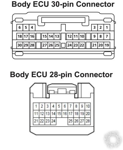
Posted By: jangelj
Date Posted: June 20, 2018 at 6:31 PM
Thanks for posting that pic. It took some hunting, but that's the same pic I found in the internet. I tried to post it, but the pic was too big to upload from my phone.
So my installation is done. Took a few hours, mostly because I was trying to "figure it out". For anyone doing this, the pics posted above are priceless. Just remove the lower dash panel, leaving the airbag in place. It's 2 10mm bolts, then just pull to pop the clips. You'll have to take off the kick panel by drivers left foot first.
Then attach from the RS505 green/white, blue white, and black to Ground. I used the ground screw under the kick panel mentioned above. Green/yellow wire goes to pin 9 black wire. Blue/yellow goes to pin 24 blue wire. Both of those are in the body ECU wire harness as shown in the pics above. I found it easier to unplug the harness from the ECU while tapping into the wires. For +, I just poked around till I found a red wire with 12 volts. It was on another harness to the right of the ECU.
Those are the only wires I hooked up. I'd like to be able to unlock ALL the doors, but I'm not sure how to do that. Mostly I just need to store the keys in the van when at the gym, pool, hike, etc. as long as the drivers door opens, I'm happy.
Also, I am able to lock and unlock with the keypad and fob in any combination I have tried. I know I_walker had problems unlocking when he locked with the keypad, but I have not had that problem.
-------------
thanks!
|