2012 Hyundai Accent Manual Transmission, Viper 5706V
Printed From: the12volt.com
Forum Name: Car Security and Convenience
Forum Discription: Car Alarms, Keyless Entries, Remote Starters, Immobilizer Bypasses, Sensors, Door Locks, Window Modules, Heated Mirrors, Heated Seats, etc.
URL: https://www.the12volt.com/installbay/forum_posts.asp?tid=144217
Printed Date: May 12, 2026 at 8:44 PM
Topic: 2012 Hyundai Accent Manual Transmission, Viper 5706V
Posted By: mustafa88
Subject: 2012 Hyundai Accent Manual Transmission, Viper 5706V
Date Posted: March 08, 2018 at 11:50 AM
Hello all
My car is a Hyundai Accent 2012 manual transmission and I have a Remote Viper 5706v
The predecessor of my car is 6 Wyrat
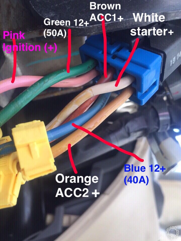
White = starter (+)
Orange = ACC2 (+)
Brown = ACC1 (+)
Pink = Ignition (+)
Green = +12 50A
Blue = +12 40A
Instruction booklet in Fiber Remot 10 WIRAT !!!
Replies:
Posted By: mustafa88
Date Posted: March 09, 2018 at 7:47 AM
Hello all
My car is a 2012 Hyundai manual transmission
I have the Viper Remot 5706v
Vipre REMOTE 9 wires
Red / Black
Pink / black
Pink / White
red
green
violet
orange
Red / White
Pink
Red / Black + Red + Red / White
Connect them all to gather
The car key start starter has 6 wires
White = starter (+) ??? Connect to any wire on vipre remote
Orange = ACC2 (+) ??? Connect to any wire on vipre remote
Brown = ACC1 (+) ??? Connect to any wire on vipre remote
Pink = Ignition (+) ???? Connect to any wire on vipre remote
Green = +12 50A ???? Connect to any wire on vipre remote
Blue = +12 40A ??? Connect to any wire on vipre remote
I need help

Posted By: kreg357
Date Posted: March 09, 2018 at 4:21 PM
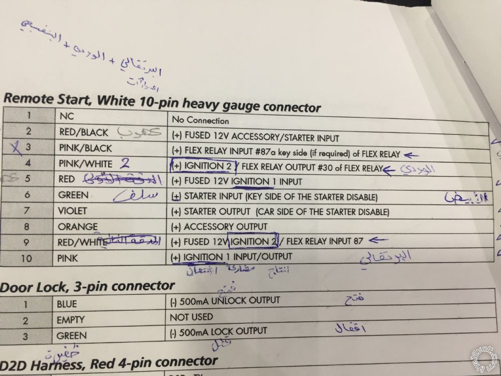
Remote Start, 10-pin heavy gauge connector
1 NC No Connection
2 RED/BLACK (+) FUSED 12V ACC/STARTER INPUT....GREEN (50A) IGNITION SWITCH BLACK 6 PIN CONN, PIN 1
3 PINK/BLACK (+) FLEX RELAY INPUT 87A................not used
4 PINK/WHITE (+) IGNITION 2 ***set to ACC2...........YELLOW IGNITION SWITCH BLACK 6 PIN CONN, PIN 6
5 RED (+) FUSED 12V IGNITION 1 INPUT................GREEN (50A) IGNITION SWITCH BLACK 6 PIN CONN, PIN 1
6 GREEN (+) STARTER INPUT (KEY SIDE)..............WHITE IGNITION SWITCH BLACK 6 PIN CONN, PIN 3
7 VIOLET (+) STARTER OUTPUT (CAR SIDE)...........WHITE IGNITION SWITCH BLACK 6 PIN CONN, PIN 3
8 ORANGE (+) ACCESSORY OUTPUT.......................ORANGE IGNITION SWITCH BLACK 6 PIN CONN, PIN 2
9 RED/WHITE (+) FUSED 12V IGNITION 2................GREEN (50A) IGNITION SWITCH BLACK 6 PIN CONN, PIN 1
10 PINK (+) IGNITION 1 INPUT/OUTPUT..................PINK IGNITION SWITCH BLACK 6 PIN CONN, PIN 4
The White Starter wire gets cut and the Viper Violet and Green wires are connected to the correct ends.
-------------
Soldering is fun!
Posted By: mustafa88
Date Posted: March 10, 2018 at 11:54 AM
Thanks for your time
But did not work
Posted By: kreg357
Date Posted: March 10, 2018 at 12:54 PM
Well, going by your photo and using the colors marked, here are the updated connections
for your car ( which, BTW, does not match a U.S. market 2012 Accent ).
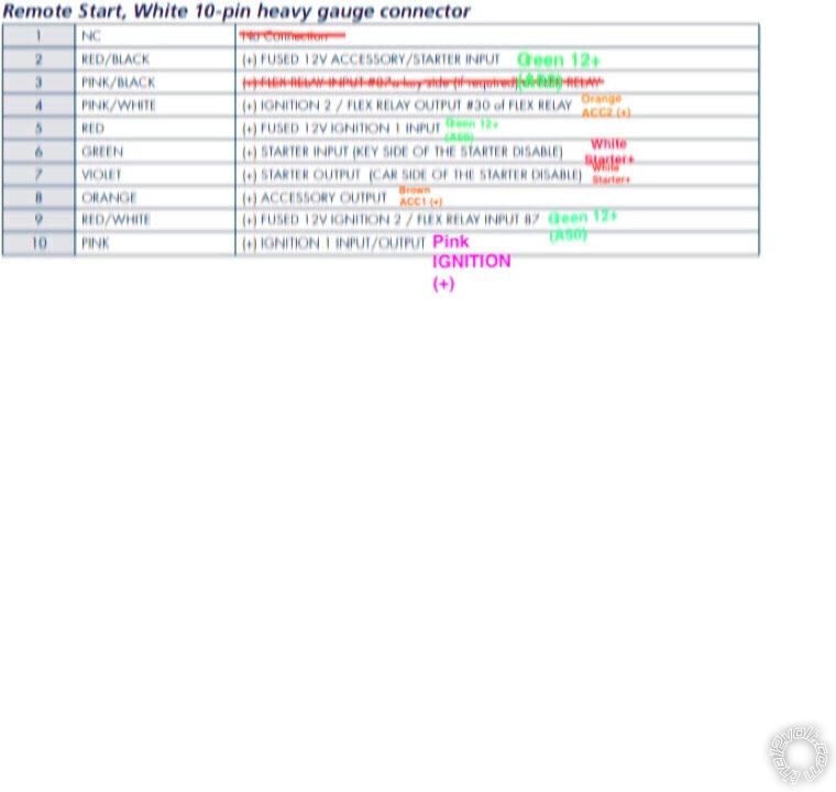
Remote Start, 10-pin heavy gauge connector
1 NC No Connection
2 RED/BLACK (+) FUSED 12V ACC/STARTER INPUT......Blue (40A) IGNITION SWITCH BLACK 6 PIN CONN, PIN 5
3 PINK/BLACK (+) FLEX RELAY INPUT 87A...................not used
4 PINK/WHITE (+) IGNITION 2 ***set to ACC2...............Orange IGNITION SWITCH BLACK 6 PIN CONN, PIN 6
5 RED (+) FUSED 12V IGNITION 1 INPUT....................GREEN (50A) IGNITION SWITCH BLACK 6 PIN CONN, PIN 1
6 GREEN (+) STARTER INPUT (KEY SIDE)..................WHITE IGNITION SWITCH BLACK 6 PIN CONN, PIN 3
7 VIOLET (+) STARTER OUTPUT (CAR SIDE)..............WHITE IGNITION SWITCH BLACK 6 PIN CONN, PIN 3
8 ORANGE (+) ACCESSORY OUTPUT..........................Brown IGNITION SWITCH BLACK 6 PIN CONN, PIN 2
9 RED/WHITE (+) FUSED 12V IGNITION 2..................GREEN (50A) IGNITION SWITCH BLACK 6 PIN CONN, PIN 1
10 PINK (+) IGNITION 1 INPUT/OUTPUT......................PINK IGNITION SWITCH BLACK 6 PIN CONN, PIN 4
Not that it matters for a simple R/S test, but the Pink/White Flex ignition output wire should be changed to
ACC2 ( Menu 3, Feature 8, Option 2 ).
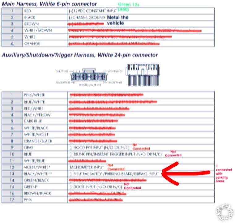
Additionally, I would connect the Viper 15 Amp Red wire in the 6 Pin connector to the vehicles +12V Blue wire
at Pin 5 to split the load between available sources ( Blue and Green wires ).
Other issues :
1. For the Viper to run in Manual Transmission Mode, the Tach wire must be connected and a successful Tach Learn preformed.
2. For the Viper to run in Manual Transmission Mode, the Door Pins and Trunk Pin must be connected properly. This is to allow
entry into Reservation Mode ( and for safety ).
3. The Hood Pin is an important safety feature and should installed and connected.
4. As a manual transmission vehicle, you must leave the Viper Menu 3, Feature 1 at its' default Option 1 setting.
5. While not shown, I'm assuming that the Brown Brake (+) wire at Pin 20 is connected.
After you make these corrections, you should be able to successfully enter Reservation Mode and then initiate a remote start.
Of course, there is one more item that needs to be addressed. Do a Remote Start Diagnostics and determine the Error Code.
Post that code and we can provide more info.
-------------
Soldering is fun!
Posted By: mustafa88
Date Posted: March 17, 2018 at 4:27 PM
The same thing does not work Maybe there is something wrong or something incomplete
I did not install the unlock and unlock feature ..Is this a reason for not starting the package remotely?
I just want to install the necessary cables to start up and then I will install the feature of opening and closing doors, hood and pouch
This cabling mode switch after the scan ..
When I turn on the engine in start The white cable will be 12+
Orange is only 12+ on the first switch but when i start it is empty of electricity, After running returns 12+
The brown is 12+ on the second switch but when I start, it is empty of electricity after running returns 12+
The pink is 12+ in the second switch but when the engine starts at the start it stays 12+ (Do not discharge the power even when operating)
+ 12 + blue + 12 blue electricity is located along or without the key
the Green 12+ and blue 12+ Electricity is present all the time with key or without
Posted By: kreg357
Date Posted: March 18, 2018 at 4:54 PM
Your voltage tests on the ignition wires confirm the labeled diagram you posted above.
Blue and Green are +12V constant
White is Starter.
Pink is Ignition.
Orange and Brown are Accessories.
As such the Remote Start, 10-pin heavy gauge connector, wiring I posted above is also correct.
As mentioned above, certain things are required for a remote start install in a vehicle with a
manual transmission. To initiate a remote start, you must first successfully enter Reservation Mode.
Please read the Viper manual for that sequence. While it won't interfere with entering Reservation
Mode, the Viper will try to lock the doors. It won't know that this wiring not connected and that
the doors did not lock, but Forum Rules prohibit discussions on bypassing safety features. Please
ensure that the Viper can control the vehicles' door locks.
Also mentioned previously, you must set the Viper up for Tach Mode and perform a successful Tach
Learn. Next comes the Door Triggers. These must be connected and working properly so the Viper
can monitor vehicle access after Reservation Mode is entered. There are no shortcuts with a
Manual Transmission install. Safety is paramount.
Please advise when you have these items done and can successfully enter Reservation Mode.
-------------
Soldering is fun!
|