Remote Start, Engine Dies After 15-20 seconds
Printed From: the12volt.com
Forum Name: Car Security and Convenience
Forum Discription: Car Alarms, Keyless Entries, Remote Starters, Immobilizer Bypasses, Sensors, Door Locks, Window Modules, Heated Mirrors, Heated Seats, etc.
URL: https://www.the12volt.com/installbay/forum_posts.asp?tid=144549
Printed Date: May 13, 2026 at 4:10 AM
Topic: Remote Start, Engine Dies After 15-20 seconds
Posted By: 84elky
Subject: Remote Start, Engine Dies After 15-20 seconds
Date Posted: June 25, 2018 at 7:07 PM
Really need some expert help. '84 El Camino G-Body. Old Clifford (Directed Electronics) 50.7X Alarm with Remote Start
Alarm and Remote Start using Virtual Tach work perfectly except for one thing: Engine dies 15-20 seconds after remote-start. Using remote start diagnostics and scanning software, have determined that after remote start and before key is turned to 'Run' position, voltage is low (approximately 10.5v) and engine runs rough resulting in remote start shutting down and engine stops. If key is turned to Run prior to engine stopping, voltage returns to 14.3v and everything is fine. Static battery voltage is 12.6v; cranking voltage = 12.1v; voltage at battery 14.3v when running normally.
Any ideas?
Thanks!
Replies:
Posted By: sparkie
Date Posted: June 25, 2018 at 7:53 PM
Check the power source you are using for the remote starter's main power. If the voltage is low on the input, the output will be the same. There could be a voltage drop inside the remote starter. They use onboard relays which may have poor contacts. Virtual tach shouldn't be used on a vehicle that old. Hardwire the tach to the engine for better results. Ideally use the battery power wires at the ignition switch. Always go a clean area of the vehicle body for ground too.
-------------
sparky
Posted By: 84elky
Date Posted: June 26, 2018 at 3:01 PM
Thanks for reply. Understand the comments about virtual tach .vs. tach wire, but engine starts properly as is so let's put that aside for a moment. Voltages at ignition switch (where everything is wired):
... 12.2v not running (At battery = 12.5v)
... 14.0v running with key on (whether started with key or remote start)
... 11.1v in off position after remote start
Also voltage differential between battery neg. and alarm ground is 0.05v (50mv). So it appears voltages and grounds are solid and not an issue.
But here's the mystery that I don't understand and would appreciate some insight because I'm not electrically inclined like most here and don't understand what is going on "under the covers". After remote start:
... 11.1v in off position
... 14.0v in run position
... toggling between off and run also yields above voltages. Nothing changes.
Any idea what might be the cause? Understand also relays internal to the brain may be iffy, but seems they would either be on or off and not in-between exactly the same way every time to cause the reduced voltage. Ditto for external relays. Surely there would appear to be another possibility. Somehow full voltage is consistently not being returned in the off position after remote start.
Thanks again anyone for any additional insight!
Posted By: sparkie
Date Posted: June 26, 2018 at 5:44 PM
If you measure 11.1 volts at the ignition switch battery wires after shut down, measure the voltage at the battery. If it is the same you should have your battery tested. If the voltage is higher you have a voltage drop somewhere between the battery and the ignition switch. A voltage drop can occur through a wire, across a connection or fuse/fusible link. Any resistance in a circuit will cause the drop. Connect the tach wire and learn tach. If you disconnect the ignition coil and crank the engine, measure the voltage at the ignition switch. There must be a load on the circuit to see if the voltage drops. Make sure that the battery terminals are clean and tight. Make sure that the battery ground to chassis is good.
-------------
sparky
Posted By: 84elky
Date Posted: June 27, 2018 at 10:17 AM
Appreciate your comments but feel am not communicating the problem very well. I believe what is being seen is not the classic battery/alternator/ignition switch voltage drop because of these numbers. It seems like an incorrect remote start wiring issue which was the purpose of my initial question:
... 12.5v at battery not running
... 12.2v at ignition switch not running
... 14.2v at battery running = alternator not a problem
... 14.0v at ignition switch running = wiring battery to switch ok
... 11.0v cranking at battery with coil disconnected at 15 seconds = ok
... 10.8v cranking at ignition switch with coil disconnected at 15 seconds = ok
... 0.05v drop between battery negative and alarm ground = ok
Those numbers seem to indicate no battery, alternator or current at ignition switch issue.
But now comes remote start where the problem arises and trying to describe problem differently with some new information:
- The 11.1v occurs while engine is running immediately after remote start with key in Off position
- Put in key and turn on and get 14.2v (shown above)
- While running, can turn key between on and off and the voltage will consistently change from 11.1v when key Off and 14.2v when on
Why?
AND -- just discovered yesterday that A/C-heater blower is NOT running after remote start while key is in off position. Turn key on and blower is on; turn key off and blower again off . . . . That would seem to indicate perhaps an accessory relay was not installed, but the question again because I don't understand the circuitry: Even if there was no accessory relay, what in the alarm wiring might cause the 11.1v??? It's not the ignition switch because everything works fine if start with key. Just trying to get some insight from someone who understands the internals of remote start wiring as to what to look for before tearing everything apart that is not in an easy to get to area under dash. Hope this makes sense.
BTW, this not an old, factory car. It's a 400HP injected show car that had a complete frame-on restoration several years ago. Virtually everything is new and spotlessly clean, but the alarm was installed by the previous owner.
Posted By: 84elky
Date Posted: June 27, 2018 at 1:10 PM
More info to above post ----------
Changed both SPDT relays (assume accessory and starter because can't trace wiring without total disassembly). No change in performance.
And discovered differences between key and remote start:
Key Start
... Key on: All gauges in normal position
... Cranking: Temp gauge to max temp until start; then returns to normal = as expected
Remote start
... Press remote start FOB button and parking lights flash once and hear a relay or relays click
... Fuel gauge immediately goes to Empty during 2-3 second fuel pump prime period before cranking. Should not move.
...... Am assuming this is duplicating the key in run position through a relay, but gauge activity is not normal. Then gauge back to normal position just before cranking as with key
... Temp gauge goes to far left while cranking = backwards from key start
This seems to clearly indicate something in remote start circuit not wired correctly.
Any ideas? Really appreciate it!
Posted By: sparkie
Date Posted: June 27, 2018 at 4:58 PM
List your wiring connections and someone who knows your system may see a problem. Its been years since I worked on a GM that old but the accessory for the HVAC may be orange. Pink is ignition, Starter may be purple or yellow. If your system has more than one main battery power input and there are 2 battery feed wires at the ignition switch, connect to both of them individually. You must hook up the tach wire though. Virtual tach won't work if you are having voltage problems.
-------------
sparky
Posted By: hagar
Date Posted: June 28, 2018 at 8:20 PM
It sounds like you missed a ignition positive with your remote start. Your alternator is not getting a turn on signal when using remote. Therfore low voltage.
Posted By: davep.
Date Posted: June 28, 2018 at 11:22 PM
I agree, the alternator is not turning on.
IIRC, the brown wire at the ignition switch has to be powered to turn on the alternator. (They use the ACCY circuit and not IGN for the alternator because when the alternator is running, it back-feeds its excite wire, and if excite is connected to the pink ignition circuit, the engine won't turn off. The pink and brown circuits are separate, that's why the used the brown wire for the older cars.)
I don't think there is an orange wire for the HVAC in an 84. I'm pretty sure there is only the brown "ACCY" wire that is hot in RUN or ACCY, but not start for everything except what is on the pink wire IGN circuit.
If you did NOT power the brown wire at the ignition switch, begin by doing that first. It should fix both of your issues. Use the orange wire on the Viper to the Brown on the switch.
Posted By: 84elky
Date Posted: June 30, 2018 at 12:26 PM
hagar and davep --
Thanks for your replies. You are correct-no voltage from alternator. Prior owner must have been in a hurry!
It seems 2 things are needed:
- Connect ACCY wire at switch to Orange on brain
- Connect exciter wire so it's hot after remote start
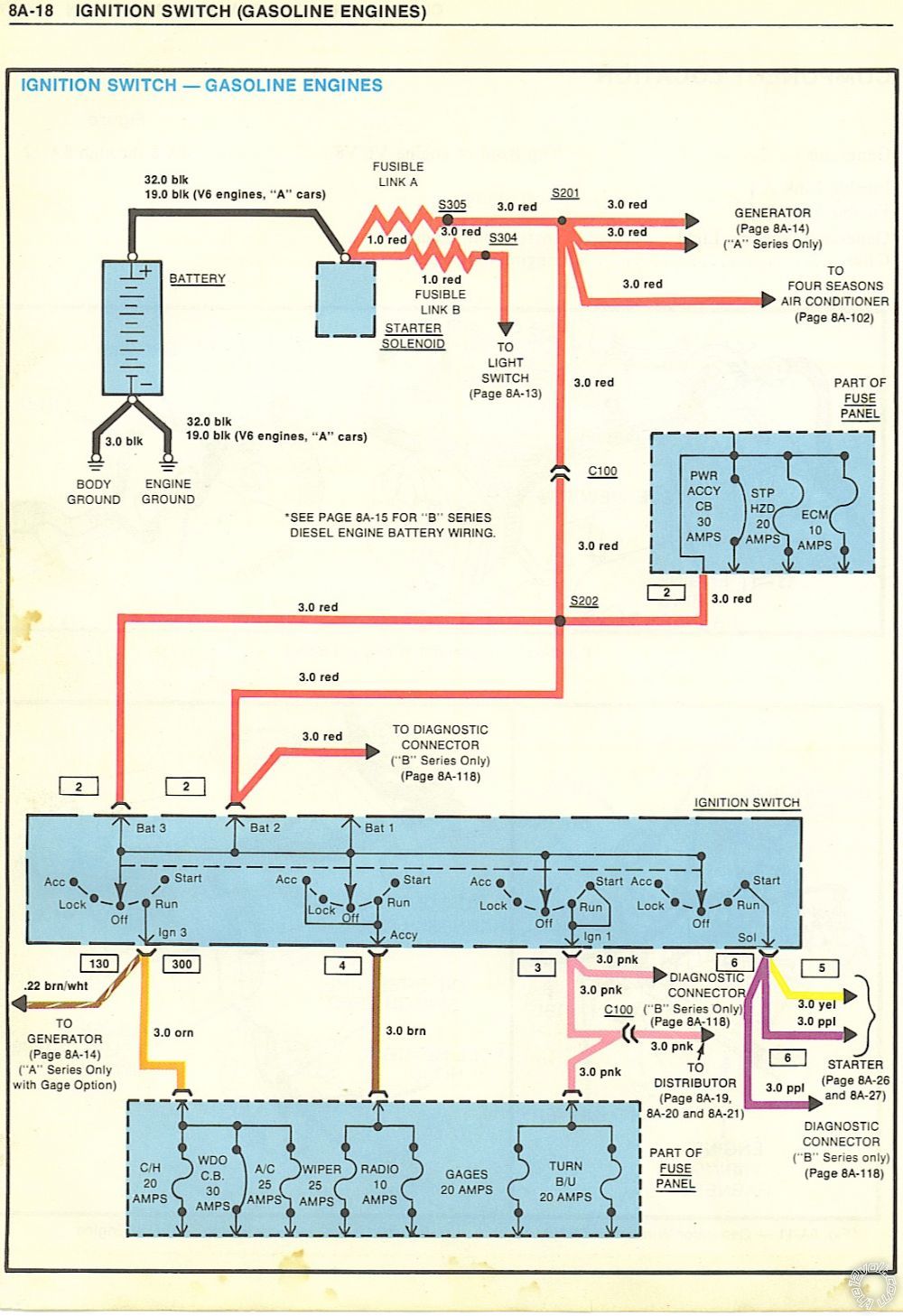
I've attached the factory wiring diagrams for the ignition switch and charging circuit. It shows there are 2 ACCY wires:
... Brown = wipers and radio (don't need this)
... Orange = Choke Heater (C/H), power windows etc. (WDO) and AC (want this one)
Thus connect orange at switch to orange (Viper H3/3) on brain. Correct?
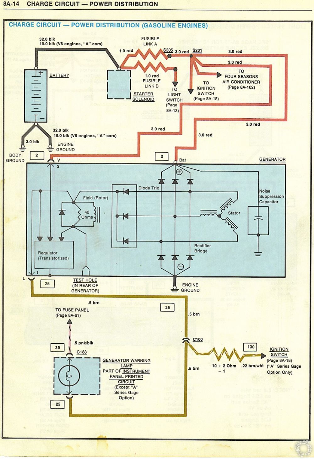
Then on ign. switch diagram there is a brown/white wire that goes from ign. switch to "generator". I believe this is the wire currently attached to the CS130 alternator "L" pin. Will verify when I wade into the abyss under the dash. Given there is no warning light (replaced with a voltage gauge), there is a resistor in this wire to substitute for the lamp resistance.
If the above is correct so far, to activate the "L" wire, would the "Viper Remote start auxiliary output, 5-pin connector, Pin 2 Orange (-) 200mA Accessory Output" be used with a SPDT relay? If so, would really appreciate your suggestion as to 85,86,87,30 connections. Or is it acceptable to put the "L" wire on the Viper H3/3 Orange Accessory Output along with the accessories? Or other options?
**********
EDIT TO ORIGINAL POST: Could "H3/7 Pink/White (+) Ignition 2 / Flex Relay Output" be used for "L" wire by programming Menu 3=Remote Start, Item 8=Flex Relay Function, Feature 2=Accessory. Wouldn't that activate it only during run and not cranking?
**********
Thanks in advance for your help!!!
PS -- Is it normal for fuel gauge to show Empty (apparently shorted to ground) when the parking lights are flashed? That's also happening.
Posted By: davep.
Date Posted: July 02, 2018 at 4:44 PM
I would connect a switched in IGN only wire to the "I" terminal on the CS 130 and disconnect the "L" wire. The I terminal does not require resistance, and will turn on the alternator just like the L terminal does. Neither I or L of a CS130 will back-feed the ignition circuit like the original 84 alternators did, so you can connect the I terminal directly to say, the pink wire on the ignition coil.
Posted By: 84elky
Date Posted: July 02, 2018 at 4:57 PM
davep. wrote:
I agree, the alternator is not turning on.
IIRC, the brown wire at the ignition switch has to be powered to turn on the alternator. (They use the ACCY circuit and not IGN for the alternator because when the alternator is running, it back-feeds its excite wire, and if excite is connected to the pink ignition circuit, the engine won't turn off. The pink and brown circuits are separate, that's why the used the brown wire for the older cars.)
UPDATE---
Davep, you are again correct about brown wire being accessory. Finally tore under-dash apart and probed. There is also an orange wire per the wiring diagram, but it is NOT accessory. It's only hot during run and appears to power the AC blower, etc. And please disregard my blather about a separate relay for "L" wire. I totally read past what you posted about wiring brown.
Will be attaching brown to remote start accessory tomorrow and will report findings.
Again, thanks for the help and insight!
Posted By: 84elky
Date Posted: July 02, 2018 at 11:41 PM
davep. wrote:
I would connect a switched in IGN only wire to the "I" terminal on the CS 130 and disconnect the "L" wire. The I terminal does not require resistance, and will turn on the alternator just like the L terminal does. Neither I or L of a CS130 will back-feed the ignition circuit like the original 84 alternators did, so you can connect the I terminal directly to say, the pink wire on the ignition coil.
My alternator is PFLS so have no "I" terminal. Not sure I understand.
Posted By: 84elky
Date Posted: July 03, 2018 at 1:50 PM
SOLVED!!! Thanks to all who contributed, and especially davep for his wiring guidance.
Solution: Orange ignition switch wire to Orange Viper ACCY Output
This agrees with the wiring diagrams posted above which show a brown/white wire splitting off the orange wire (both hot in run only), which attaches to the "L" post of the factory generator. Brown/white must come out of the harness somewhere behind the instrument panel which I can't see.
Independently tried Brown ignition switch to Viper Orange, but strangely had no alternator output after remote start regardless of key position (off or run). No clue why but matters not. Orange works so Brown not used.
Again, thanks to all! And just thinking--how were issues like this resolved before the internet and people willing to help others?
PS for sparky ---
Located tach wire under dash. Verified it is tach wire with continuity test of under dash wire to tach post on coil. Connected to Viper Violet/White Tach wire and changed Viper Menu 3, Feature 2 to Option 4=Tachometer. Engine tries to start, actually firing before the 0.6 sec cranking time ends but immediately dies every time. This was after attempting to "learn" the tach signal:
... Start with key
... Within 5 secs, press valet switch and hold
... After 3 seconds valet LED should light
... Release switch
Do the above and never see light. Nothing.
While it's a mute point because Virtual Tach is working perfectly every time, I'm curious why Tach wire start is failing if anyone has ideas.
Thanks again!
Posted By: sparkie
Date Posted: July 03, 2018 at 2:37 PM
I'm glad you got it going. I don't know what wire you connected to for tach inside but it may not be correct. On older vehicles like yours, I always run a wire under the hood for tach. Virtual tach works on many vehicles but is better suited for modern engines. There are still newer vehicles which aren't compatible with it such as Hyundai and Kia. If it starts and runs, leave it. It you find at times it has problems starting, then run a wire under hood to negative side of coil or tach output from distributor. The tach wire should measure between 1 and 9 volts AC and increase with engine RPM.
-------------
sparky
|