2008 Dodge Grand Caravan, Remote Start Install
Printed From: the12volt.com
Forum Name: Car Security and Convenience
Forum Discription: Car Alarms, Keyless Entries, Remote Starters, Immobilizer Bypasses, Sensors, Door Locks, Window Modules, Heated Mirrors, Heated Seats, etc.
URL: https://www.the12volt.com/installbay/forum_posts.asp?tid=144757
Printed Date: May 12, 2026 at 9:16 PM
Topic: 2008 Dodge Grand Caravan, Remote Start Install
Posted By: kennyd.
Subject: 2008 Dodge Grand Caravan, Remote Start Install
Date Posted: September 23, 2018 at 10:31 PM
hey guys I need some help with installing the Aux wire from my remote starter for a 08 Grand Caravan SE. I would like to use this wire to activate the rear defrost. do I need a relay? Do I set it up as latched or pulse? I'm using a CodeAlarm CA5354 with a Fortin bypass.
thanks guys.
Replies:
Posted By: kreg357
Date Posted: September 24, 2018 at 7:19 AM
Here is a link to a Pictorial on your van. https://www.the12volt.com/installbay/forum_posts.asp?tid=130163
It shows the Rear Defrost wire. You will need a 30/40 Amp relay to handle the current. It needs a (+) latched type output fused at 30 Amps.
-------------
Soldering is fun!
Posted By: kennyd.
Date Posted: September 24, 2018 at 12:56 PM
Thanks for the help! May I ask where I can get the tach signals wire? Di I connect to injectors or coil pack? If so which wire what colour?
Posted By: kennyd.
Date Posted: September 24, 2018 at 1:00 PM
Also do I need separate relays for the door locks? I can't seem to locate the wires from the driver kick panel for the door locks?
Posted By: kreg357
Date Posted: September 24, 2018 at 3:42 PM
Which Fortin bypass module?
-------------
Soldering is fun!
Posted By: kennyd.
Date Posted: September 24, 2018 at 5:45 PM
Its an Evo All. I dont know if it programmed correctly using their guide. Blue led just turns on (no key inserted). Then turning the ignition key on, blue led turns off. Turn ignition key off, blue led turns on. no flashing blue led like it says in the onle guide. Tried to remote start, using tackless mode in the code alarm ( door lock wires and tach wire not connected because I cant find the wires)
The ignition 1 pink wire (Evo All- yellow and yellow/red also connected) from the remote start is connected to the vehicle side of the pink and white stripe wire from the ignition harness which is cut like in the fortin guide. Connector sode of the ignition harness, pink and white wire connected to the yellow/green Evo All. The remote start accesory orange wire and purple starter wire are not used!
Using the fortins online trouble shooter, not knowing if I programmed the bypass module correctly, it mentions connect ground while running wire? The only wire similar to the ground while running, is the remote starters blue/black wire, called the start status/active output.
Posted By: kreg357
Date Posted: September 24, 2018 at 7:07 PM
The Fortin EVO-ALL comes preloaded with Firmware Version 4.09. That should be all you need. If you download the install guide ( #5131 ), you will see on Page 1 all of the functions handled by the bypass module. These include Lock, Unlock, Arm, Disarm, Hatch, Sliding Doors, Tach, Door Status, Trunk Status, E-Brake Status, Brake Status and the immobilizer bypass. That is why your questions about locks and Tach confused me.
First verify that the white label on the module and box indicate Ver 4.09 firmware. The first step of programming does a Factory Reset on the module, clearing everything previously done. Are you going D2D between the EVO-ALL and the CA5354? I am not a CodeAlarm user and can't find an install guide for your CA5354 system. The one guide I did find leads me to believe that it's D2D protocol is DBI. That will be a problem if it is. You must switch the EVO-ALL over to DBI if you want to go with the D2D harness. The EVO-ALL come set for another D2D protocol and won't work. If you have the FlashLink2 cable,. you can do this yourself. If not, you must switch over to the W2W installation method.
I guess at this point you should list all your wire connections, too.
-------------
Soldering is fun!
Posted By: kennyd.
Date Posted: September 24, 2018 at 7:24 PM
My wires at this point is Wire to wire! The code alarm remote starters use flashlogic bypass modules! Only afew wires are used for the ignition with the evo all. The harware and software are the latest versions and meets the minimum requirments,
Posted By: kennyd.
Date Posted: September 24, 2018 at 7:27 PM
I was hoping someone can help me where I can find the door lock wires and tach wires, ans where they are located!
Posted By: kreg357
Date Posted: September 24, 2018 at 8:21 PM
You might be right. I may not the best person to assist you with this install....
I'm still confused. If you are using a full featured bypass module that handles the caravans door locks and supplies you with a good Tach signal, why do you need to know their location in the van. Below is the wiring diagram for the Fortin EVO-ALL bypass module :
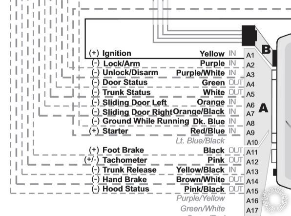
Lock is the Purple wire at Pin A2
Unlock is Purple/White at Pin A3
Tach is at the Pink wire at Pin A12
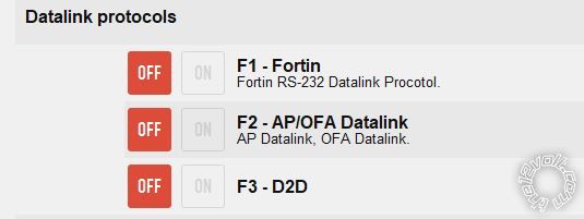
If Code Alarm systems only support Flashlogic bypass modules which use the DBI protocol, then you would need to set the EVO-ALL Option F3 as shown below :
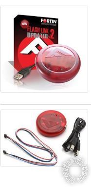
This is done using the Fortin FlashLink2 cable pictured below :
But to finally answer your question, here is the info you requested :
Lock VIOLET\DK GREEN (- 330 OHMS) DRIVER KICK
Unlock SAME AS LOCK WIRE (- 100 OHMS)DRIVER KICK
This is a one wire multiplex lock system. You might need two relays besides the listed value resistors to make it work.
Tach Signal NOT BROWN\WHITE ANY FUEL INJECTOR ------------- Soldering is fun!
Posted By: kennyd.
Date Posted: September 25, 2018 at 6:00 AM
No no you have been very helpful kreg. Thank you very much! Ive been searching that diver kick panel for the door lock wires, I cant find the purple and green wire. I must be blind or something, it must be there! I'll have to recheck all my connections again!
Posted By: kreg357
Date Posted: September 25, 2018 at 7:14 AM
Dumb question, but if the EVO-ALL handles the locks and alarm for you via its connection to the vans CAN Bus system, why do you need to locate those wires?
The EVO-ALL install guide shows all the necessary connections including the R/S units +12V power, chassis ground and Parking Lights. Other than possibly the Horn or Hood Pin, there shouldn't be any other connections needed or made to the van for this install.
-------------
Soldering is fun!
Posted By: kennyd.
Date Posted: September 26, 2018 at 4:45 PM
Yes your correct! Since Im having trouble finding some of the wire on the vehicle, Im going to connect all the wires back to the evo-all, My question is when I tried programming the evo-all it doesn't flash like its supposed to in the guide, so I don' t know if its programmed or not. Im going to start all over this weekend! I'll post back what Ive done Thank you for all your replies!!
Posted By: kennyd.
Date Posted: October 20, 2018 at 7:06 PM
hi kreg, so I just purchased the forton flashlink manager and connected tp my evoall, updated the software. I've made changes to the setting and have changed the datalink protocols to F3 D2D setting to "ON". Unfortunatly while I was following the programming steps I still do not get the Flashing BULE LED, to confirm programming was successful.
I've been double and triple checking the two CAN lines. the wiring harness from the WIN module in the fortin guide show two CAN line wires and one of wires are colored white/grey, and one white/blue. I followed the wiring diagram pictures from the Evoall to the remote start and connections to the WIN module wiring harness
I still can't seem to get passed the programming part?
In the fortin flashlink manager in the left column I selected my vehicle, installation and connection types, I selected to Standard installation and standard connection, and alarm system to No alarm system
what else should I check?
Posted By: kreg357
Date Posted: October 22, 2018 at 8:21 PM
All the sources I have indicate that the twisted pair CAN wires at the ignition switch node are White/Brown and White/Light Blue. Here is a diagram of the Node Connector :
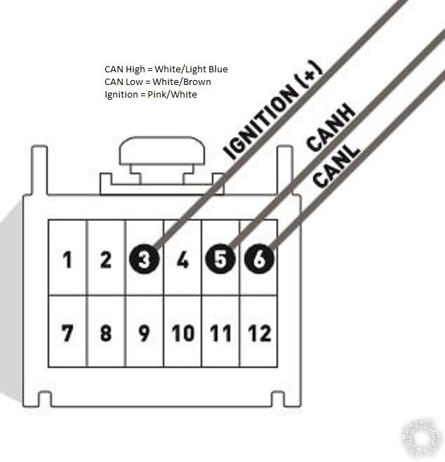
Double check these wires. All connections should be soldered. ------------- Soldering is fun!
Posted By: kennyd.
Date Posted: October 23, 2018 at 8:04 PM
In the fortin guide Can High is whilte/grey and Can Low is white/Lt. blue? Are the fortin guides worng? Thanks very much Kreg! I will double check the node connector this week and give you an update? Here is the link from the fortin website Q&A page where I posted my problem! https://fortin.ca/en/qa/84114/evo-all-not-programming-on-08-dodge-grand-caravan?show=84114#q84114
Posted By: kennyd.
Date Posted: November 18, 2018 at 9:46 PM
Hi kreg, sorry for the late response, I've been buzy with work and other things!! Anyway I got started this evening and checked the two CAN wires and I had Both HIGH and LOW mixed up! Your diagram which I followed were correct and compared to the fortin installation guide the CAN wire colors were wrong. Switched the wires with the diagram you gave me and the programming procedure with the fortin evoall went flawlessly, the procedure was exactly as in the fortin guide. Door locks work perfectly!
Now I've tried remote starting with the codealarm remote remote start module clicks, the evoall LED turns Orange, but no lights on initial start on the cluster gauge? All the lights do not light up in the dash cluster?
I have the pink wire ignition 1 wire (remote start module) with yellow wire (ignition evoall) with yellow/red (COMM2 evoall) connected to pink/white to the vehicle side of the wiring harness of the WIN ignition harness.
Also 12V Battery wire (remote start module) with yellow/blue (NO2 evoall) connected to 5amp fuse connected to light blue/red 12V (WIN Module wiring harness)
Start wire (remote start module) connected to starter wire (evoall module). Everything is connected exactly like in the fortin guide. Any ideas guys?
Posted By: kreg357
Date Posted: November 19, 2018 at 2:51 AM
Perhaps an omission, but you did not mention the EVO-ALL Yellow/Green wire at Pin D1. On the early Grand Caravans ( 2008 - 2010 ) you must cut the mini-vans' Red/White Ignition wire and make the wire connections exactly as shown in the Install Guide #5131 Page 3 of 5. Additionally, connector and vehicle side wiring connections are critical.
Are you going D2D, using the 4 Pin data harness or W2W with the 4 Pin harness just supplying power and ground and all the other connections between the Code Alarma and EVO-ALL hardwired? If W2W, then the Starter wire connection you mentioned is needed, but in D2D mode it is handled by the D2D 4 Pin harness.
Have you programmed he Code Alarm to Tach Mode and done a successful Tach Learn?
-------------
Soldering is fun!
Posted By: kennyd.
Date Posted: November 19, 2018 at 6:04 PM
Oh yes I forgot to mention, the yellow/green wire (evoall) connected red/white to the ignition wring harness to the WIN. The red/white wire is cut, just like the fortin diagram. The connection is direct wire to wire soldered, NOT Data 2 Data.
The code alarm is set to tachless mode, just to see if the remote start works. Do I need to Program the tach first? Does this prevent the dash to light up when I try to remote start the vehicle?
The starter wire is connected to the start wire of the evoall.
Im following the troubleshooter from the fortin website, Im checking all of my connections of the yellow wires of the evoall, and all the wires to the start and ignition wires.
Posted By: kreg357
Date Posted: November 22, 2018 at 9:40 AM
Well, OK. Here goes. I am not a CodeAlarm user and was unable to find a CA5354 Install guide. Therefore this response will be not exact on the CA5354 side. That includes jumpers, options and feature programming. I believe the CA 5354 is a R/S w/Keyless entry only and has no alarm features ( siren, etc ).
It would appear that you are going in the W2W method between the CA5354 and the EVO-ALL.That is fine but does require inter-module wiring. Being as you obtained the Fortin FlashLink cable and flashed the correct firmware and made the F3 D2D option setting, you could go D2D.
Here is the needed wiring for W2W mode :
First you must cut the D2D harness from the EVO-ALL and connect the Red wire to +12V constant and the Black wire to Chassis Ground. The Blue and White wires are not used and should be insulated. When you start the EVO-ALL programming process, the EVO-ALL checks the status of the Blue and White wires and decides on D2D or W2W mode. I would just connect the Red and Black wires to the correcponding wires of the CA5354 ( thick Red 12V and Black Chassis Ground ) near the CA5354.
In W2W mode all of the dashed lines from the R/S to the EVO-ALL must be made with a hardwire connection for all the necessary signals. These would include :
A1 Yellow Ignition ( has to be hardwired for both W2W and D2D ) as shown in EVO-ALL diagram
A2 Purple Lock/Arm to CA5354 Green Lock wire only
A3 Purple/White Unlock/Disarm to CA5354 Blue Unlock wire only
A8 Dark Blue GWR to CA5354 Start Status / Active Output (-)
A11 Black Foor Brake to CA 5354 Brown/Red Brake (+)
A12 Pink Tach to CA5354 Purple/White ( optional but recommeneded to run in Tach Mode )
A15 Pink/Black Hood Pin to CA5354 Grey Hood Pin *
* This signal will only be present if the minivan has a Factory Alarm system and Hood Pin. If the minivan does not have a factory hood pin, you must install the CA6364 kit supplied hood pin.
It would appear that the EVO-ALL is connected to the CAN system properly being as it programmed as per the install guide. You have double checked the other vehicle wiring at the ignition node connector. I believe that the Grand Caravan has one touch starting, so the Tach signal and running in Tach Mode is not mandatory or even real important. You could just set the CA5354 to a fixed 1 second starter output if it has that optiom / feature.
-------------
Soldering is fun!
Posted By: kennyd.
Date Posted: November 22, 2018 at 8:07 PM
Thanks kreg, when programming the evoall with the link manager, I did set it to F3 D2D. Will check everything this weekend!
Posted By: kennyd.
Date Posted: November 25, 2018 at 6:48 PM
So I have check all my wiring they all seem to be correct, followed the troubleshooting guides in the fortin website. tested wires yellow/red from the evo when attempting to remote start, I get 12 volts. tested the yellow/blue from the evo as the guide states I should always get 12 volts constant. which I get 12 volts constant. but the guide states the EVO should have a RED LED when attempting to remote start and that the Ground while Running wire should be checked? and that's where I think I have a problem, the EVO only lights up an ORANGE LED.
I'm in the final stretch of my install, I'm so close. I'm taking my time with this install, as I do not want to screw things up.
I am still going to check my ignition output wire from the remote starter if I am getting voltage, and program the Tach wire to vehicle, which I still not have done, just to rule things out.
Posted By: kreg357
Date Posted: November 25, 2018 at 7:54 PM
The GWR signal is generated by the CA5354 R/S and is a (-) signal. You should be able to test this signal by connecting a Digital Multi Meter to this wire connection between the EVO-ALL and the CA5354 :
A8 Dark Blue GWR to CA5354 Start Status / Active Output (-)
The DMM set up is as follows :
20 V DC
Red test lead to +12V constant source
Black test lead to EVO-ALL Pin A8 Dark Blue wire
The meter should read 0V. When you initiate a remote start, the DMM should go to +12V indiacting that the CA5354 is outputting a (-) GWR signal going to the EVO-ALL.
-------------
Soldering is fun!
Posted By: kennyd.
Date Posted: September 18, 2021 at 7:56 PM
Hi kreg, So I have had to put this install on hold for quite some time as life happened. So I wanted to get back to the install and apologize for not replying back. :oops:
I don't have 0volts, when remote start is initiated. It stays a 12V. the Ignition and the Start output is what I think is not working correctly. I hear the relay clicking and the remote fob beeping, tries to start the vehicle three times, then stops and the the ignition lights and dinging from the dash stays on until I put the key in and turn to ACC and the back to off position.
CA5354 Starter output wire (Purple)>>>>>>EVO-ALL Starter wire (Red Blue)
CA5354 Ignition 1wire (Pink)>>>>>>vehicle Harness side of the Immobilizer connector wire (Red White)
I've noticed that the Ca5354 has 2 Ignition wires 1 and 2 and the Red White wire from the vehicle harness side of the immobilizer connector is coloured like a dark pink with a white strip, and the EVO-ALL wiring diagram shows to as a Red with a white strip. there is no other wire that is coloured RED on the immobilizer harness wiring. I've programmed the tach signal already from the CA5354. I don't know what else to check?
|