Viper 5002, 2005 F250, Secondary Doors Unlock
Printed From: the12volt.com
Forum Name: Car Security and Convenience
Forum Discription: Car Alarms, Keyless Entries, Remote Starters, Immobilizer Bypasses, Sensors, Door Locks, Window Modules, Heated Mirrors, Heated Seats, etc.
URL: https://www.the12volt.com/installbay/forum_posts.asp?tid=144960
Printed Date: March 28, 2026 at 2:28 AM
Topic: Viper 5002, 2005 F250, Secondary Doors Unlock
Posted By: Agdodge4x4
Subject: Viper 5002, 2005 F250, Secondary Doors Unlock
Date Posted: November 20, 2018 at 4:29 PM
As some of my old posts indicated, I had trouble with my alarm system. Well, I managed to find a brand new in box system and now need help enabling features the original installer did not enable. One of these features is my secondary unlock feature. I now have the 'auxiliary wiring harness' which I did not before. However, i Have no idea how the H2/1 needs to be hooked up. Can someone point me in the right direction? As installed, it's 'all or nothing' when unlocking. Thanks!!
I have this post here:
https://www.the12volt.com/installbay/forum_posts.asp?tid=141528&tpn=5#719015
I understand this post, but I am not clear where to find the BCM Unlock wire in which to wire that.
Replies:
Posted By: iskidoo
Date Posted: November 20, 2018 at 10:05 PM
Took a bit of reading but hes basically saying to remove the currently connected 1st alarm unlock wire from the trucks unlock wire. Then wire the alarms 2nd unlock output to that same truck unlock wire. Then you would wire the alarms first unlock wire that you disconnected and wire it to the driver door motor circuit that he posted on the last page of the 2016 thread.
-------------
Steve G
Posted By: Agdodge4x4
Date Posted: November 21, 2018 at 11:15 AM
Thank you. I think I got it.
OK, so the 'second unlock' is basically going to unlock ALL of them, even though the driver door would be unlocked already with the first push. So the first button sends the unlock signal to the driver door, and the second unlock sends the unlock signal to ALL doors, which means the drivers door gets hit with two unlock signals when we are done. Is this the typical way to doing it?
Posted By: Agdodge4x4
Date Posted: November 27, 2018 at 4:28 PM
I still have a problem. I got my new alarm brain installed. However, I have a wire that is not hooked up that I found.
Found two wires disconnected. No idea where they go as they have connectors on them so they should have mating connectors.
DOOR LOCK HARNESS:
GREEN/BLACK Lock #30 Common (Output) ------> Hooked up to a White wire with red tracer in my drivers kick panel
BLUE/BLACK UNLOCK #30 Common (Output) ------> Hooked up on the wire that is Black with white tracer in the kick panel
MAIN HARNESS
GREEN (-) Door Trigger Input, Zone 3 -----> ???? This wire has a connector but its just loose in the door. No idea where this should go. It doesn't look like it was ever hooked up. SHould it be? If so, where?
Can someone shed light on where this should go?
Also, I have a bitwriter, and I have saved my OLD configuration, but I cannot get it to program my new alarm (identical brain). I'd also like to program the old remote to the new brain. How do I copy settings?
Posted By: iskidoo
Date Posted: November 27, 2018 at 6:12 PM
Are you wired into the GEM system to wake up the system before attempting unlock? I think your truck goes to sleep after 5 minutes and needs to be woken before unlock will work from an aftermarket system.
GEM wake-up
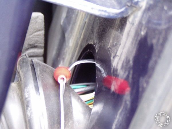
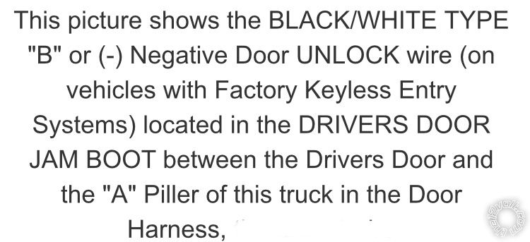
Also, when I look at note #2 on the following vehicle wiring diagram it mentions that the unlock wire is found at the harness coming in through the door jam. Maybe the wire in the kick is only for all other doors. Just a thought. Im not sure. Maybe someone else may know better.
2005 Ford F250 Wiring Diagram------------- Steve G
Posted By: iskidoo
Date Posted: November 27, 2018 at 6:17 PM
This photo also appears at the bottom of the previously posted wiring diagram.
 ------------- Steve G
Posted By: iskidoo
Date Posted: November 27, 2018 at 6:31 PM
How did you verify the unlock output on the new brain? Did you test for a negative pulse at the end of the wire? Try testing the wire right out of the connector where it plugs into the brain. If it works there then perhaps you have a break in the wire between the brain and the other end of the wire where your connection was made.
-------------
Steve G
Posted By: Agdodge4x4
Date Posted: November 27, 2018 at 6:37 PM
FYI...everything locks and unlocks on the new brain. The only question I have now is where this green wire goes:
MAIN HARNESS
GREEN (-) Door Trigger Input, Zone 3 -----> ???? This wire has a connector but its just loose in the door. No idea where this should go. It doesn't look like it was ever hooked up. SHould it be? If so, where?
The wire appears to not be used, although the original installers put a connector on it. Should this be hooked up?
Can someone shed light on where this should go?
ON SECOND THOUGHT...
That green wire shouldn't be hooked up at all. My (+) DOOR TRIGGER INPUT and OUTPUT OF DOME SUPERVISION RELAY #30 are both hooked into the BLACK/BLUE wire in my kickpanel which I assume is the dome light. So....the green wire doesn't even get used on this install.
Posted By: iskidoo
Date Posted: November 27, 2018 at 7:01 PM
Sounds like youve got it all figured out. Good job. Enjoy.
-------------
Steve G
Posted By: Agdodge4x4
Date Posted: November 27, 2018 at 9:50 PM
Note quite. I wanted to 'copy' my old settings from the old brain to the new brain using my BitWriter. However, It does not allow me to copy. When I load the file, it seems to take, but do I have to go through each menu item and 'write' it to the system? When I try that, I get an error about 'no remote'. Is that because I have not programmed my OLD remotes to the NEW system? What do I need to do to copy all the settings?
|