I successfully installed a Viper 211HV to my Toyota 2016 Land Cruiser Series 70 pick-up truck thanks to various post on the12volt.coms forum. My truck did not have a factory installed central locking system, so I installed the door actuators and connected all the wires to the Viper unit. Currently it only locks/unlocks with the supplied remotes, flashes the hazards and honks the horn. Here is how it is wired:
211HV Connector
18 - blank
17 brown/black stripe - chassis ground
16 - blank
15 yellow - ignition 12 volt (switched)
14 - blank
13 - blank
12 brown - horn
11 black - chassis ground
10 - white - parking light output
09 - violet - 12 volt battery
08 - blue/black stripe - door actuator (lock)
07 - violet/black stripe - 12 volt battery
06 white/black stripe - chassis ground
05 - green/black stripe - door actuator (unlock)
04 - blank
03 - blank
02 - blank
01 - red - 12 volt battery
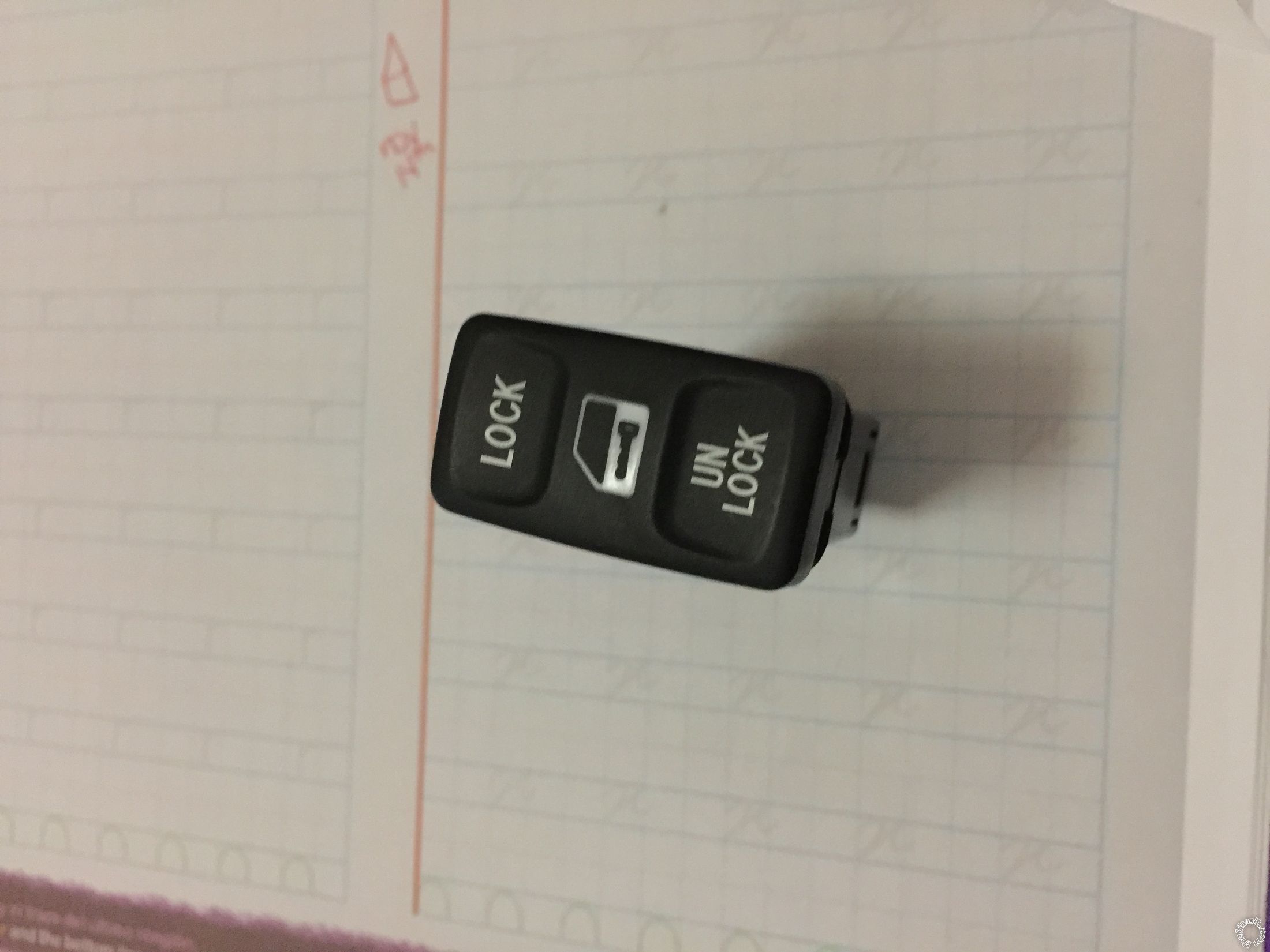
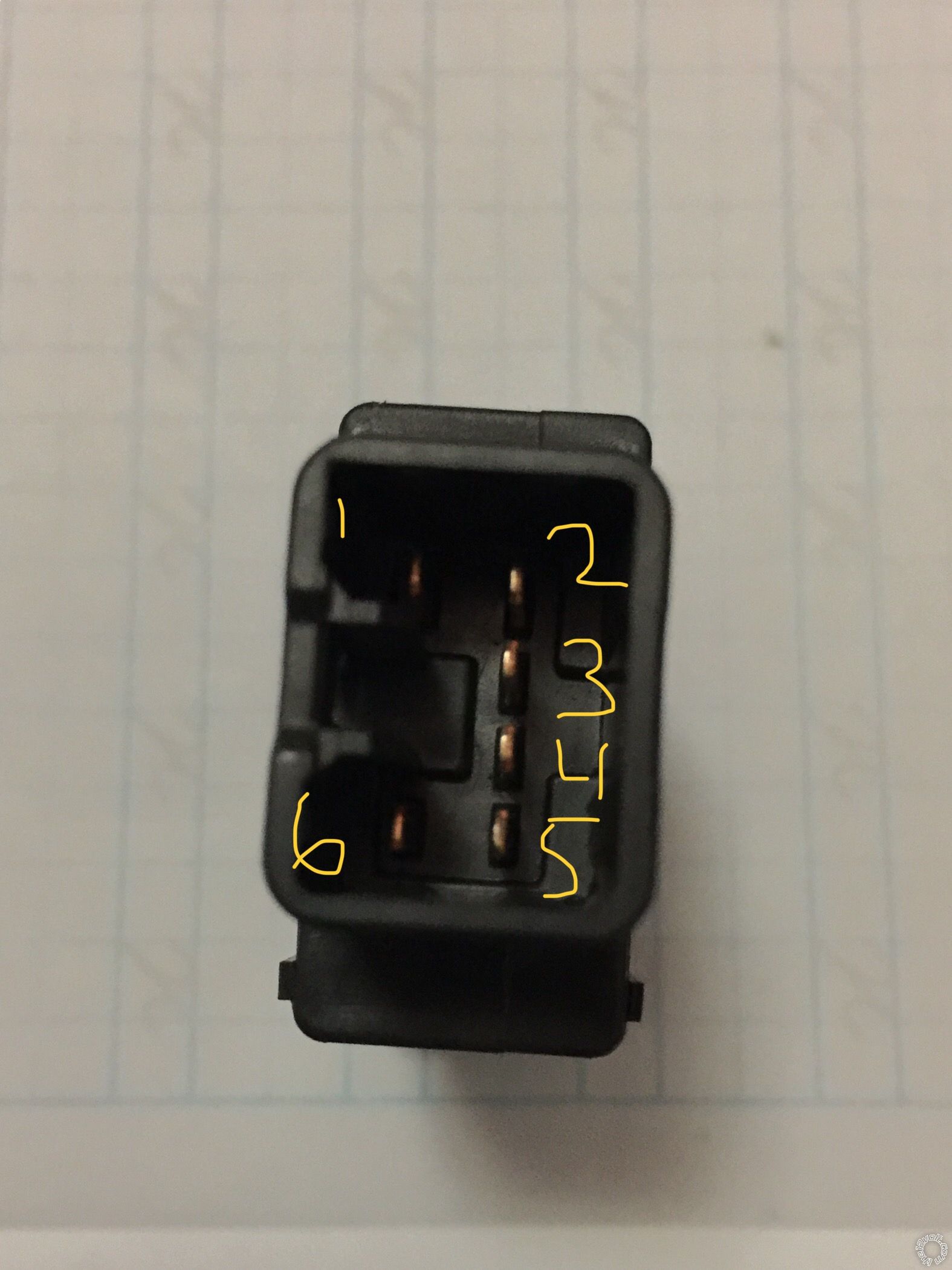
I purchased the original dash mounted door lock/unlock switch from my Toyota dealer and want to add it to the Viper 211HV so that it works in tandem with the remotes. I have read a couple of post regarding adding a DPDT switch (https://www.the12volt.com/installbay/forum_posts.asp?tid=142120 and https://www.the12volt.com/installbay/forum_posts.asp?tid=142157). My switch has 6 pins but I dont know what type of switch I have. See pictures below.
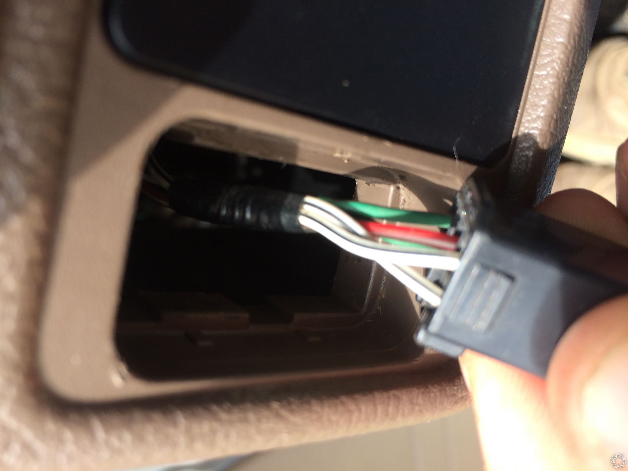
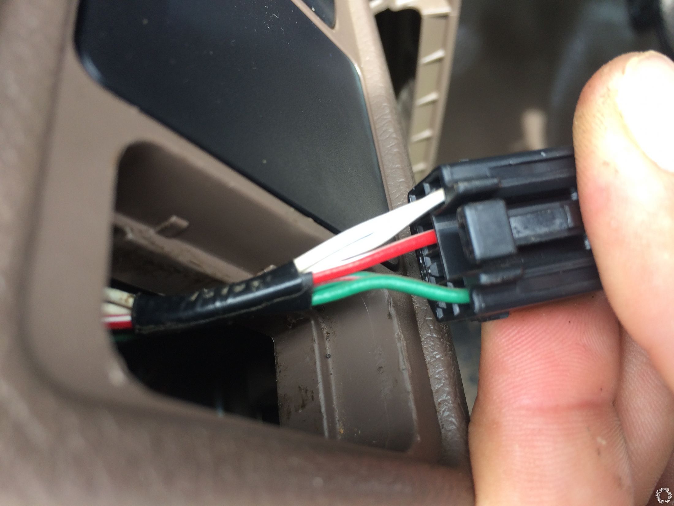
My friend has the exact same truck but his has a factory central locking system. I used a test light to test the wires connected to the switch and these are the results:
1 white/black stripe ground
2 white/black stripe ground
3 red/white stripe unlocks when probe touches but does not light up probe
4 NO WIRE
5 green/red stripe - locks when probe touches but does not light up probe
6 green dimmer/panel probe lights up when lateral/head lights turned on
Is this a DPDT switch? Will I need relays as mentioned in the posts noted above?
I also found these diagrams on previous post from the12volt.com forum.
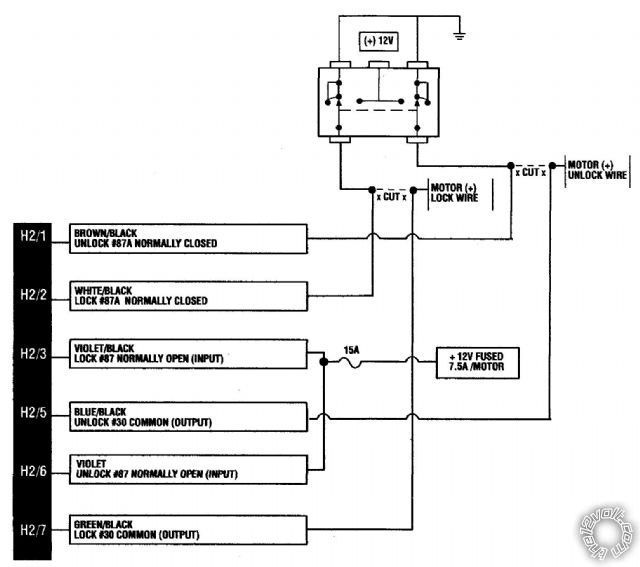
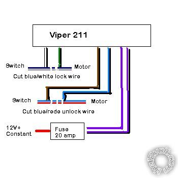
Or will it work if I connect it like the pictures; where the Viper 06-white/black stripe connects to the switch 05-green/red stripe and the Viper 17-brown/black stripe connects to the switch 03-red/white stripe? Do I need to add +12v to the factory switch? I need help on what wires I need to connect. I dont want to burn the unit. Thank you.
After lots of research and learning about relays, I figured out that I needed two relays. Here is how its wired:
Lock Relay:
#30 to actuators wire that is LOCK
#87 = B+, Hot at all times. (Fused)
#87a = H1/5 - Green/Black wire Viper 211 HV
#86 = B+, Hot at all times. (Fused)
#85 = Pin 5 on OEM Toyota switch (LOCK trigger)
Unlock Relay:
#30 to actuators wire that is UNLOCK
#87 = B+, Hot at all times. (Fused)
#87a = H1/8 - Blue/Black wire Viper 211 HV
#86 = B+, Hot at all times. (Fused)
#85 = Pin 3 on OEM Toyota switch (UNLOCK trigger)
On the 211HV:
H1/5 Green/Black = #87a, LOCK relay.
H1/8 Blue/Black = #87a, UNLOCK relay.
Dash switch:
Pin 1 = Ground
Pin 2 = Ground
Pin 3 = #85 Unlock Relay
Pin 4 = Not Used
Pin 5 = #85 Lock Relay
Pin 6 = Panel Dimmer Lights
Circuit Description:
I connected the Viper Common Outputs (H1/8 Blue/Black to the Unlock relay & H1/5 Green/Black wire to the Lock relay) to #87a since it is a closed circuit when the relay is at rest. I connected the actuator wires to #30 which is a common and a fused hot wire to #87. Now the Viper unit is in a closed circuit (#87a & #30) when the relay is at rest, the unit will be allowed to send a positive (+) signal to the actuators when activated by the Viper remote and a negative (-) signal when at rest. I connected a fused hot wire to #86 and a switch output wire (which are both negative) to #85. When the OEM switch is pressed the negative signal on #85 and positive signal from #86 causes the relays internal switch to close the circuit for #87 & #30 and open the circuit for #87a & #30. Now #87 will only send a positive signal to #30 (actuators) while the OEM switch is pressed. When the OEM switch returns to its resting position, the relays internal switch will return to resting position as well; closing the circuit for the Viper unit/actuators and opening the circuit for the OEM switch/actuators.
I hope that this will help someone as past the12volt.com posts helped me.