2008 Chrysler 300, Prestige APS787E
Printed From: the12volt.com
Forum Name: Car Security and Convenience
Forum Discription: Car Alarms, Keyless Entries, Remote Starters, Immobilizer Bypasses, Sensors, Door Locks, Window Modules, Heated Mirrors, Heated Seats, etc.
URL: https://www.the12volt.com/installbay/forum_posts.asp?tid=145188
Printed Date: April 27, 2026 at 10:38 AM
Topic: 2008 Chrysler 300, Prestige APS787E
Posted By: antman1
Subject: 2008 Chrysler 300, Prestige APS787E
Date Posted: January 26, 2019 at 9:10 AM
would anyone be able to assist me? I need to figure out this install, my friend changed to having me install this in his 2008 Chrysler 300. I have been looking at this Transponder bypass "Directed Electronics DEI EXPRESSKIT CHALL BYPASS MODULE (FOR CHRYSLER)" Here is the manual for the alarm: https://www.manualslib.com/manual/806483/Prestige-Aps-787e.html
I will be installing it in a 2008 Chrysler 300. Please help me figure this out. I really appreciate it..
Replies:
Posted By: kreg357
Date Posted: January 26, 2019 at 9:56 AM
Being as you have a Chrysler vehicle that uses the iDatalink default CH4 firmware,
I think I would go with an ADS AL-CA or FLCAN bypass module. As mentioned, they
come from the factory flashed with the needed CH4 firmware. The CH4 firmware is
the correct firmware for your Chrysler 300. The iDatalink bypass module are rock
solid and can go D2D with your chosen R/S unit. The Prestige APS 787E default
D2D protocol is DBI and that is the D2D protocol on the FLCAN bypass module. If
you get the ADS AL-CA module, you will have to make one programming change on the
APS787E to support the needed ADS D2D protocol. Programming the APS units is
pretty easy with the remotes.
Here is a link to the FLCAN with CH4 firmware install guide for your 300 :
https://images.idatalink.com/corporate/Content/Manuals/DL-CH4/DBI-AL(DL)-CH4-EN_20180425.pdf
The chart on Page 2 indicates the supported features. You would follow the Type 2
install diagram. While it looks complicated, it's not. In D2D mode all of the dashed
Red connections are made via the D2D connection. The relay isn't needed because you
would be getting a current production FLCAN module that has a H/W version of 1.24 or
better. You would need a 5 amp fuse and a 1N4001 diode. The fuse holder could be one
from the APS787E because you could combine the two +12V input wires into one, with one
fuse, and use the other for the 5 amp IGN line. You could do the bypass module to R/S
connections on the bench. Aside from the 5 vehicle connections shown on the Type 2
diagram, you would need both power and ground to the APS 787E and a hood pin.
-------------
Soldering is fun!
Posted By: antman1
Date Posted: January 26, 2019 at 11:51 AM
Is this the bypass you are talking about? What would I ask the seller to insure it is flashed to the right firmware?
https://rover./rover/0/0/0?mpre=https%3A%2F%2Fwww.%2Fulk%2Fitm%2F113539405765
Posted By: kreg357
Date Posted: January 27, 2019 at 9:44 AM
For some reason I can't get the link to work. There are several online sources for that bypass module. EBay, Amazon, Crutchfield and Sonic Electronics come to mind. Pretty sure the default firmware loaded at the factory will be fine, as long as has never been opened / used. For the FLCAN its FLC AL(DL) CH4 and on the ADS AL-CA its ADS AL(DL) CH4.
-------------
Soldering is fun!
Posted By: antman1
Date Posted: January 27, 2019 at 11:52 AM
This link work?
https://www./itm/IDATALINK-ADS-AL-CA-IMMOBILIZER-BYPASS-MODULE-DOORLOCK-CANBUS-INTERFACE/113539405765
Posted By: kreg357
Date Posted: January 27, 2019 at 6:02 PM
While the link didn't work, the "113539405765" is an eBay item number that is exactly what you want.
In the auction, the item picture shows the current H/W version number and the correct firmware. You
will have to change the APS787E programming, Feature 18 to Option 2 to support D2D to this bypass module.
-------------
Soldering is fun!
Posted By: antman1
Date Posted: January 27, 2019 at 7:40 PM
Here is what I have so far...
Prestige APS787E Wiring draft for 2008 Chrysler 300 w/IDATALINK ADS-AL-CA IMMOBILIZER BYPASS MODULE DOORLOCK & CANBUS INTERFACE
22 Pin Main Wiring Harness #1124300:
1.) Green/White Dome Light Output (-): N/C
2.) LT. Blue Ground While Running Output (-): idatalink (Blue/White)
3.) Black/White Horn Output (-): N/C
4.) Purple (+) Door Trigger Input: N/C
5.) Brown/Black (+) Inhibit/Shutdown To Brake Switch: idatalink (Orange)
6.) DK. Blue/Black External Remote Start Trigger input (-): N/C
7.) Orange/Black (-) Parking Brake Input: idatalink (Green)
8.) Green/Yellow Glow Plug Input: idatalink (Pink/Black)
9.) Brown (-) Door Trigger Input: idatalink (Yellow/Black)
10.) Green/Orange Tachometer input: idatalink (Purple/White)
11.) DK. Green - (-) Instant Trigger Input: N/C
12.) DK. Blue Channel 3 Trunk Release Output (-): N/C
13.) Green/Black Channel 4 Output (-): N/C
14.) DK. Blue/Red Channel 7 Output (-): N/C
15.) Black/LT. Green Pulse After Start Output (-): N/C
16.) Black/Blue Pulse Before Start Output (-): N/C
17.) Black/Red Pulse After Shut Down Output (-): N/C
18.) Black/Yellow Pulse During Crank Output (-):N/C
19.) LT. Blue/Black Channel 6 Output (-): N/C
20.) LT. Blue/Green Channel 5 Output (-): N/C
21.) Gray/Black (-) Inhibit/Shutdown to Hood Switch: Optional Add Later
22.) Orange Starter Inhibit Relay Control (-): N/C
8 Pin Power/Starter Harness # 1124299 NOT SURE IF STARTER WIRES NEEDED WITH IDATALINK??
1.) Blue Ignition 1 (+) : PINK/WHITE (+) @ IGNITION SWITCH HARNESS
2.) Red/White Batter 1 12v (+): LIGHT BLUE/RED (+) @ IGNITION SWITCH HARNESS
3.) Green Ignition 2 (+) : N/C
4.) Pink Ignition 3 Common Contact : N/C
5.) Purple Accessory (+) : NOT SURE??
6.) Red Battery 2 12v (+): N/C
7.) Yellow Starter Output : PINK/DARK GREEN (+) @ IGNITION SWITCH HARNESS
8.) Red/Black Ignition 3 Normally Open Contact : N/C
4 Pin 2nd Main Harness #1124301:
1.) Black Chassis Ground
2.) White/Red Parking Light Relay Input
3.) White/Black (+) Siren Output
4.) White Parking Light Relay Output: idatalink (white)
3 Pin Door Lock Output Harness #1122906
1.) Red (-) Door Lock Output : idatalink (Green/Black)
2.) Green (-) Door Unlock Output: idatalink (Blue/Black)
3.) Red/Black (-) 2nd Door Unlock Output : N/C
4 Pin Shock Sensor Harness #1122591
1.) Blue Predetect
2.) Green Full Trigger
3.) Black Chassis Ground
4.) Red - + 12 Volts
6 Pin Antenna Harness #1124296
1.) Red - +5 VDC
2.) Green Rx
3.) Black Ground
4.) Gray Valet Enable
5.) Blue LED Cathode
6.) NC
iDATALINK MODULE
To Be continued. Not sure on rest or wiring and what relays or diodes or resisters will be needed with idatalink
. Any help mucho appreciated.
Posted By: kreg357
Date Posted: January 27, 2019 at 8:54 PM
Looks pretty good. Here are some corrections and additions.
You are going W2W with the manual wire connections between the APS787E and the ADS AL-CA,
so you must set the ADS AL-CA to Standard Hardwired Mode prior to vehicle programming.
No parking light relay needed with ADS AL-CA H/W Ver 1.24.
1.) Green/White Dome Light Output (-): N/C
2.) LT. Blue Ground While Running Output (-): idatalink (Blue/White)
3.) Black/White Horn Output (-): N/C
4.) Purple (+) Door Trigger Input: N/C
5.) Brown/Black (+) Inhibit/Shutdown To Brake Switch: idatalink (Orange)
6.) DK. Blue/Black External Remote Start Trigger input (-): N/C
7.) Orange/Black (-) Parking Brake Input: Not needed, turbo timer only idatalink (Green)
8.) Green/Yellow Glow Plug Input: Not needed - not Diesel idatalink (Pink/Black)
9.) Brown (-) Door Trigger Input: idatalink (Yellow/Black)
10.) Green/Orange Tachometer input: idatalink (Purple/White)
11.) DK. Green - (-) Instant Trigger Input: Trunk pin input iData Yellow/Red
12.) DK. Blue Channel 3 Trunk Release Output (-): iData Red/White
13.) Green/Black Channel 4 Output (-): N/C
14.) DK. Blue/Red Channel 7 Output (-): N/C
15.) Black/LT. Green Pulse After Start Output (-): N/C
16.) Black/Blue Pulse Before Start Output (-): iData Brown
17.) Black/Red Pulse After Shut Down Output (-): N/C
18.) Black/Yellow Pulse During Crank Output (-): N/C
19.) LT. Blue/Black Channel 6 Output (-): N/C
20.) LT. Blue/Green Channel 5 Output (-): N/C
21.) Gray/Black (-) Inhibit/Shutdown to Hood Switch: use mercury switch
22.) Orange Starter Inhibit Relay Control (-): N/C
1 Blue Ignition 1 (+) follow iData diagram, 5 A fuse, 1N4001 diode, etc
2 Red/White Battery 1 - 12V (+) Combine with Pin 6 Red, fuse down to 20 Amps
3 Green Ignition 2 (+) not used
4 Pink Ignition 3 Common Contact not used
5 Purple Accessory (+) not used
6 Red Battery 2 - 12V (+) combined with Red/White Pin 2 to Red/White in Passenger Kick Panel
7 Yellow Starter Output to iData Black/White
8 Red/Black Ignition 3 Normally Open Contact not used
4 Pin 2nd Main Harness #1124301:
1.) Black Chassis Ground chassis ground
2.) White/Red Parking Light Relay Input to thick Red/White Pin 2 main ign harness
3.) White/Black (+) Siren Output siren
4.) White Parking Light Relay Output:idatalink (white)
3 Pin Door Lock Output Harness #1122906
1.) Red (-) Door Lock Output : idatalink (Green/Black)
2.) Green (-) Door Unlock Output: idatalink (Blue/Black)
3.) Red/Black (-) 2nd Door Unlock Output : N/C
-------------
Soldering is fun!
Posted By: antman1
Date Posted: January 27, 2019 at 11:52 PM
Thank you, I'll keep you posted on how it goes and try to post pictures. 😎
Posted By: antman1
Date Posted: February 05, 2019 at 1:35 PM
I'm doing my vehicle prep wiring for the alarm right now and I'm noticing a few things that I have some questions about on the relay numbers 85 and 87 I'm not sure which wire goes on those?
On the idata the wires black/white , green, purple/yellow and purple/black are they not used on this install?
The white/red wire on the APS787E is confusing. Is it going to connect to 85 on the relay?
also I'm a little confused on how the unit is going to connect to the onboard computer of the car?
Posted By: kreg357
Date Posted: February 05, 2019 at 8:44 PM
The ADS AL-CA Black/White (+) Starter Input wire will be connected to the APS787E thick Yellow (+) Starter Output wire ( as mentioned above ).
The ADS AL-CA Green (-) EBrake Status output wire is not used for your application. ( Manual Transmission only )
The ADS AL-CA Purple/Yellow and Purple/Black wires are not used for your application. ( unless you gat sliding door on your 300 )
The white/red wire on the APS787E is confusing. Is it going to connect to 85 on the relay? Two things here. Number one, you don't need an external relay. ( unless the ADS AL-CA has a H/W version less than 1.24 )
The APS787E White/Red wire is the input to the APS787E's internal Parking Light relay. As mentioned above, it goes to a +12V constant source. The easiest place is the thick Red or Red/White wire. The APS787E's
White Parking Light output wire is now a (+) output and connects to the ADS AL-CA White wire as shown in the diagram and mentioned above. The ADS AL-CA turns this signal into the proper MUX signal that the 300
needs and gets from the ADS AL-CA Yellow wire.
For the most part, the ADS AL-CA controls the car via its' connections to the vehicles' CAN bus ( CAN Hi and CAN Lo ).
-------------
Soldering is fun!
Posted By: antman1
Date Posted: February 06, 2019 at 8:33 AM
Thank you so much this really helps I'll go and take the relay that I was putting on off now. unfortunately I ran out of solder, once I get it soldered and all my wiring is prepped and I have everything labeled the way I want it labeled to go in the car I'll take pictures of my prep work to show everyone.
Posted By: antman1
Date Posted: February 09, 2019 at 3:47 PM
I got all the wiring prep completed and have a couple wires in question that I dont see on any diagrams for vehicle wiring for the chrysler 300 2008 model. the wires are CANH and CANL? Where would these wires be located for me to get this completed? Thank you so much for your help. I will post pics soon of the alarm and idata prepped.
Posted By: kreg357
Date Posted: February 09, 2019 at 5:12 PM
Going by the ADS AL-CA w/CH-4 Install Guide #58513, you will be following the
Type 2 Install Diagram. This is on Page 7 of 11. In that guide on Page 4, it has
the 300 wire connection info, as follows :
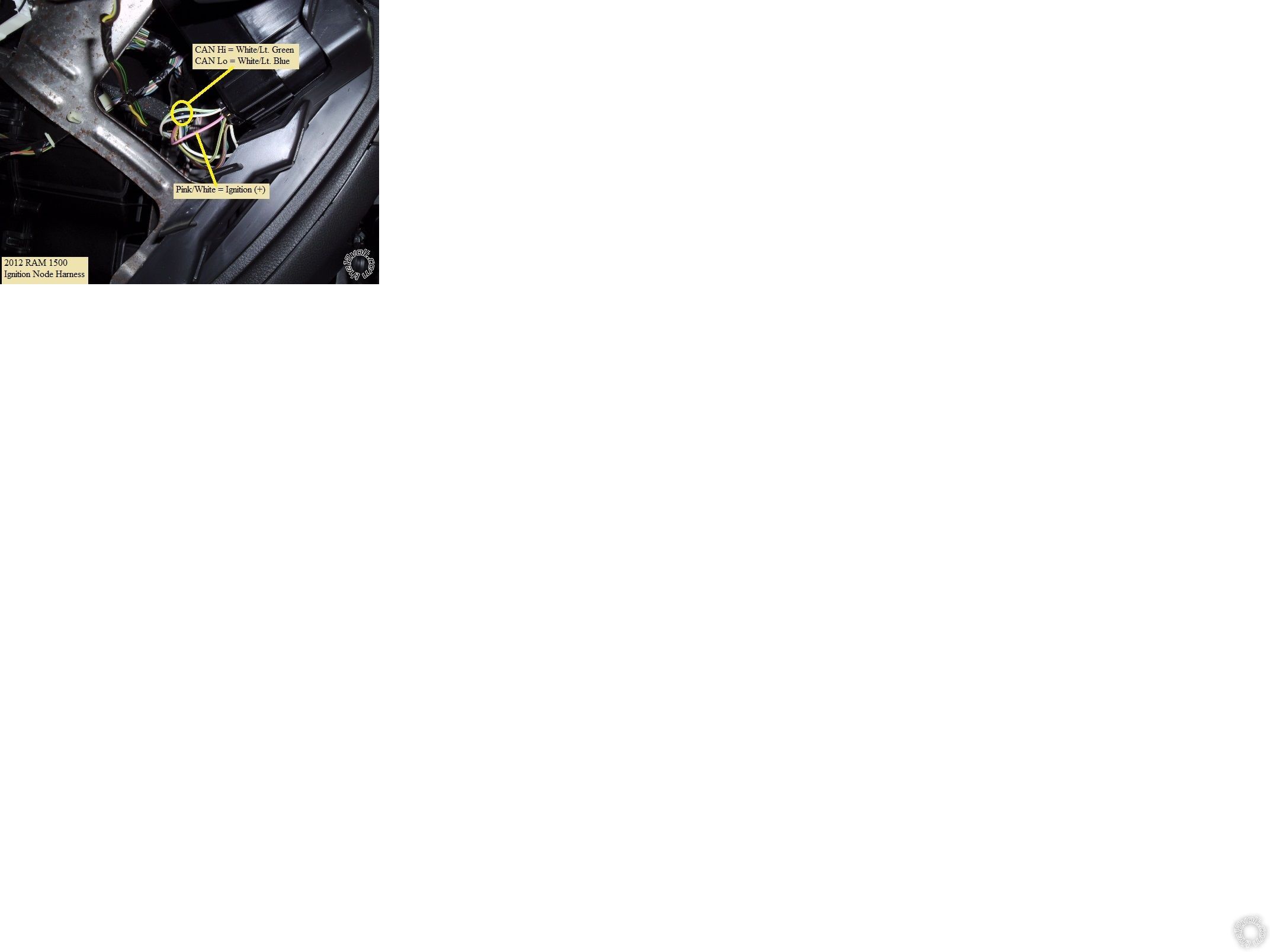
According to the ADS CH4 install guide, those 2 CAN wires can be found at the
300's Ignition Node 12 Pin Plug. The CAN High wire is White/Black at Pin 5 and
the CAN Low wire is White/Light Blue at Pin 6. Below is a photo of an ignition
node plug and harness from Dodge RAM that is similar.
 ------------- Soldering is fun!
Posted By: antman1
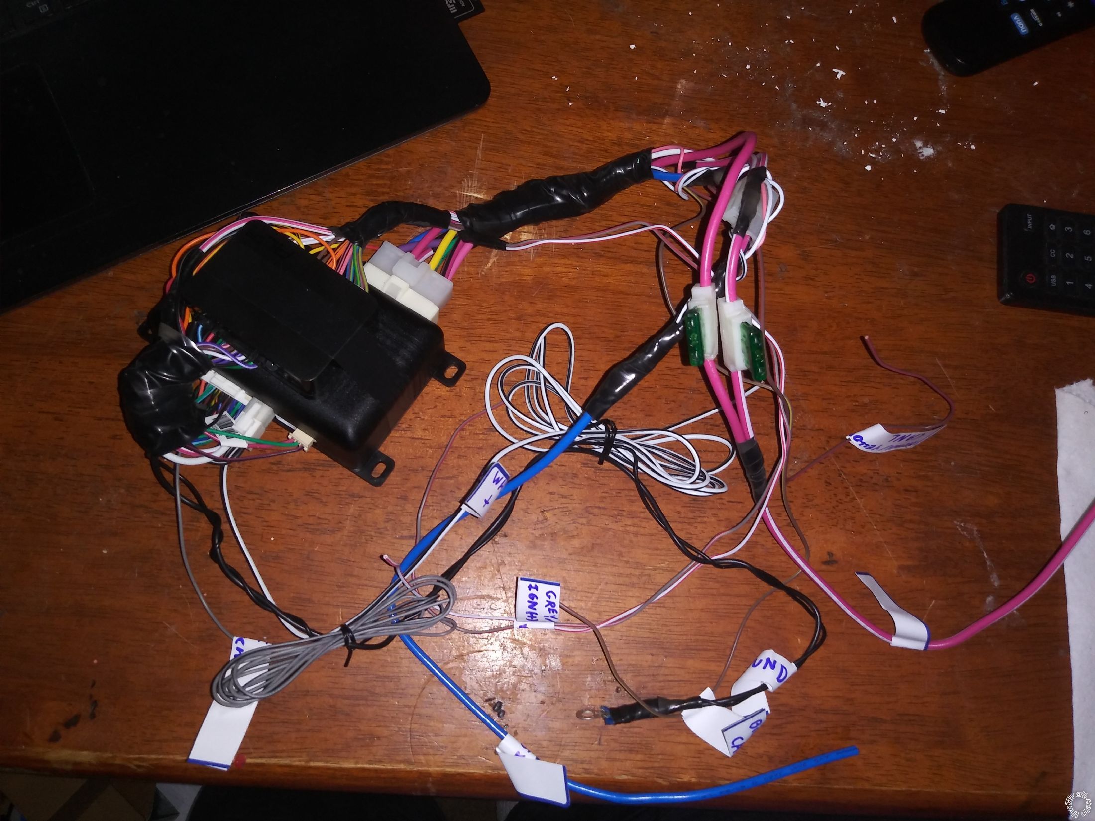
Date Posted: February 10, 2019 at 1:29 PM
Here is my prepped alarm wiring. I cant install in the car until this weather gets better though.
Posted By: antman1
Date Posted: March 04, 2019 at 3:30 PM
i started installing this today and issue is that the ADS Module does not see anything the car is doing. I cant seem to get it to respond. Can anyone assist?
Posted By: antman1
Date Posted: March 05, 2019 at 7:21 PM
Ok, I got it programmed and lock and unlock and trunk functions work. But I can't get it to remote start and the parking lights don't flash or do anything with the alarm. Could the ADS module be not programmed right or the alarm not be programmed for remote start?
Posted By: kreg357
Date Posted: March 05, 2019 at 9:15 PM
A few things you should double check...
For the Parking Lights :
Verify that the APS787E is outputting a (+) signal on it's White Parking Light output
wire when you press Unlock. You should see two (+) pulses. This white wire should be
connected to the ADS AL-CA's PARKING LIGHT (+) INPUT WHITE wire. Also verify that the
ADS AL-CA's Yellow wire is connected to the 300's White/Brown Parking Light MUX wire.
Again, no relay is need, just a direct Yellow to White/Brown connection.
For the Remote Start function :
The Factory Default programming for the APS787E is Tach Mode. If you haven't changed
this setting you should verify that the ADS AL-CA Purple/White Tach Output wire is
connected to the AS7897E's Green/Orange Tach Input wire. Next you must follow the
instructions to preform a successful Tach Learn. If that doesn't get the R/S to work,
verify that the APS787E's Light Blue GWR wire is connected to the ADS AL-CA's
Blue/White GWR Input wire.
-------------
Soldering is fun!
|