92 Ford Mustang GT, Keyless Entry Installation Trouble
Printed From: the12volt.com
Forum Name: Car Security and Convenience
Forum Discription: Car Alarms, Keyless Entries, Remote Starters, Immobilizer Bypasses, Sensors, Door Locks, Window Modules, Heated Mirrors, Heated Seats, etc.
URL: https://www.the12volt.com/installbay/forum_posts.asp?tid=145252
Printed Date: April 30, 2026 at 7:08 AM
Topic: 92 Ford Mustang GT, Keyless Entry Installation Trouble
Posted By: nick92
Subject: 92 Ford Mustang GT, Keyless Entry Installation Trouble
Date Posted: February 18, 2019 at 9:04 PM
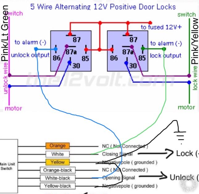
Hi, I'm installing keyless entry on a 92 Mustang GT. This seems reasonably straightforward but I'm having issues anyway. This is the wiring diagram for the Mustang door lock circuit.
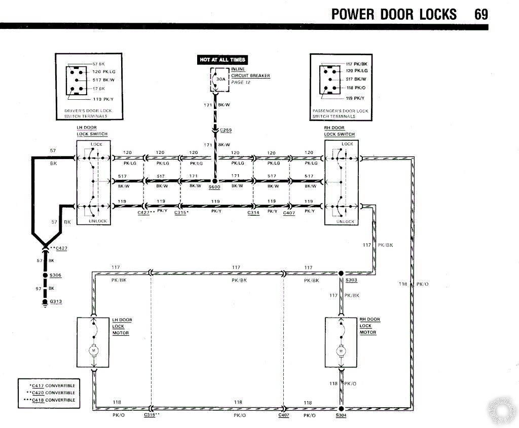
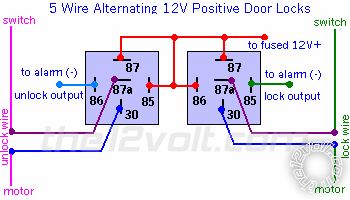
I'm using this wiring diagram from the site as a guide.
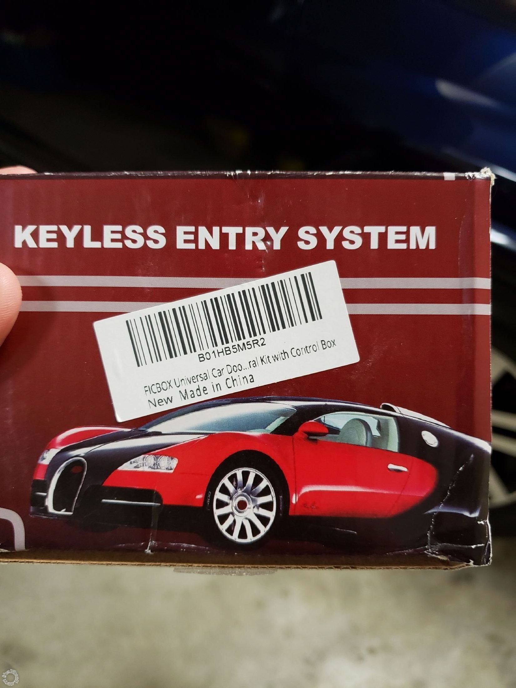
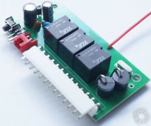
The kit I bought is a cheap unit made 8n China. This is a pic of the box.
I wired the system up and the locks worked using the rocker switches on the doors. When I tried using the keyless entry they made a little noise but didn't work. After a few tries the door rockets wouldn't even work. I took the driver's side door switch out and it appears to have been over loaded.
Just for testing purposes I wired post 87 straight to the battery with a 14 gauge wire. Post 85 and 86 are wired with a much smaller wire as they don't really carry a load.
Before I hooked up the relays to the car wiring I tested the key fob and the system activated the relays with no issues.
Any ideas why this isn't working?
Replies:
Posted By: nick92
Date Posted: February 18, 2019 at 9:05 PM
Pic of the keyless entry unit.
Posted By: iskidoo
Date Posted: February 19, 2019 at 9:08 PM
Which color wires did you attach to in the Mustang for lock and unlock?
Lock should be Pink/Yellow
Unlock should be Pink/Light Green
Both would be in the driver kick panel.
Did you use a fuse when you ran the power to the battery for testing? If not then you probably need to get a replacement door switch before proceeding. Getting everything back to normal will be necessary before troubleshooting further.
The unit you are using seems to have onboard relays built in. Is there a particular reason you are using another pair of relays after the keyless module? Figure E could have been used to wire into the locking system from the keyless system.
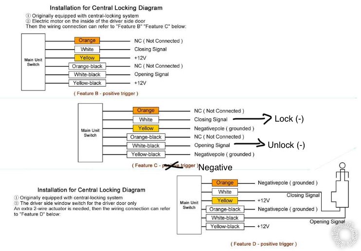
The way you are doing it is fine and will probably be more reliable since the additional relays will be rated higher than the onboard ones. Im assuming you used the Figure C diagram to provide the negative lock and unlock pulses to your add-on relays? It appears they have a typo in the manual so I marked it up a little to make it clearer.
 ------------- Steve G
Posted By: nick92
Date Posted: February 19, 2019 at 10:26 PM
I cut into the pink/yellow and pink/light green wires. They are behind the drivers side kick panel like you said.
I did not use a fuse on the line to the battery. What amp fuse should I use? The factory harness is utilizing that 30 amp breaker.
I already orded a replacement switch and I'm in the process of putting it back to factory.
The unit does have onboard relays but I believe thay are only rated for 200ma. The relays have to carry the load to actuate the lock poppers. Everything I read said you had to use relays.
I wired it up as shown in the above diagram with one minor change. In my system I wired both 87 terminals using a 14 gauge wire straight to the battery. For the positively charged post 85 and 86 I ran a separate 18 gauge wire from the battery. Neither wire was fused. This was supposed to be a quick test wire to confirm the system worked then wire it all into the factory system later.
The drivers side rocker switch was obviously damaged in the test. What I don't understand is how the system overloaded unless I have a short somewhere. Before I tried locking/unlocking the system with the keyless system I tested the rocker switches. They worked fine. Then I tried the keyless system and nothing happened. I could hear the relays actuate but the poppers didn't move. Then the switch quit working.
Before the switch was damaged there was an audible click when it was pressed in the lock or unlock position. After it was damaged it just moved back and forth. No click. That's when I opened it up and confirmed it was damaged.
Because it was a temp test the alarm module was sitting on the finder of my car not mounted in the car. I twisted the black negative wire, yellow wire and yellow/black wires together and put them straight to the battery (negative post). The white and white/black wires were used to go to the relays. The power wire on the alarm was also wired straight to the battery but it does have a factory installed fuse on it. Orange and orange/black are not being used. Not sure if any of that matters but thought it should be known.
Thanks for the markup on the diagram. The one that came in the box is actually correct. Still calls it closing and opening though.
Posted By: iskidoo
Date Posted: February 19, 2019 at 10:26 PM
Hope this helps and isnt confusing.
 ------------- Steve G
Posted By: iskidoo
Date Posted: February 19, 2019 at 10:55 PM
Most aftermarket keyless systems use transistors to switch the negative 200ma outputs and require relays. Your unit appears to have relays onboard and can be configured directly using the various diagrams for different lock systems. I found this image of the board inside showing the relays.
I think a 30 amp blade fuse would be best for the relay setup. The 4 power wires can all be together and then run through the fuse.
Im not sure what caused the magic smoke to be released from the switch but make sure both relays are connected to all wires and functioning as a pair when testing. If you only tried testing 1 relay at a time that would definitely cause issues. They need to reverse power and ground simultaneously when triggered and if all wires arent connected then power will be driven into a dead short and fry stuff. ------------- Steve G
Posted By: iskidoo
Date Posted: February 19, 2019 at 11:06 PM
Another thing is perhaps you may have had your switch/motor wires reversed when wiring to the relays. Its crucial that they are wired as shown in the diagram. In the kick panel it may be opposite of what you assume. There is probably a good way to test which others may be more familiar with. My first thought would be to pull the switch and check continuity between the switch output and the cut wire in the kick. Make sure you have the relay wires matched up properly with the motor side and switch side for both lock and unlock.
-------------
Steve G
Posted By: kreg357
Date Posted: February 20, 2019 at 3:01 AM
Here is one way to ID the lock motor wire sides using a DMM :
Easy way to tell which side of the cut wire is the switch
and which is the motor, is to cut the wire and then press
the button. If it shows 12v it is the switch side of the
button you just pressed. Some times it isnt always easy
to tell which end goes to the switch and which side goes
to the car.
-------------
Soldering is fun!
Posted By: nick92
Date Posted: February 20, 2019 at 2:07 PM
Thanks for all the input guys I really appreciate it. The first time I wired the system up I wired it in such a way that when I actuated the relays it sent 12 volts straight to ground. I immediately realized what I did wrong and felt like an idiot for doing it. I've learned a lot of things that way though. We all do from time to time.
The car came wired with power door locks from the factory just no keyless entry. When new the system did not utilize relays just the rocker switch on the drivers and passengers door arm rest. If I understand how the system is supposed to work both legs of the motor rest at ground. When you actuate the rocker switch one side comes off ground and is charged with 12+ volts and to other remains at ground resulting in the motors either locking or unlocking the doors. When the switch is actuated in the opposite direction the opposite action happens.
If I have the relays wired up correctly then at rest they simply maintain the circuit in its original uncut configuration. When one is actuated it charges one leg or the other so that the door lock motors lock or unlock. So, simply put they just act like another rocker switch in the system.
If the above statement is true and I wired it up correctly even if I had the lock signal actuate the unlock relay it shouldn't do anymore than just unlock instead of lock. Right? I wouldn't think if would ground the system. All I should have to do is swap the negative impulse wires. Right?
When testing I had both relays wired up, and they both seemed to work correctly. When I pressed the lock button on the key fob or the unlock button only one relay would fire. One didn't actuate to supply positive voltage and the other negative. Only one actuated to supply positive. The other one does nothing because it is already at ground through the normally closed circuit (87).
Please correct me on my understanding of how this circuit works if I am wrong. So far I have burned up two switches and one actuator motor. I'm doing something wrong. It was so disappointing the other day when it failed though, because the way I had it wired up made since.
Thanks again for all the help.
Posted By: nick92
Date Posted: February 20, 2019 at 2:08 PM
The system does not seem to work at all with one switch out so I'll have to wait for the new switch to get here before I can continue to really trouble shoot the system.
Posted By: kreg357
Date Posted: February 20, 2019 at 3:22 PM
Here is a DEI document that explains the common vehicle door lock systems :
https://www.the12volt.com/installbay/file.asp?ID=708
The Mustang is a 2 door, so a 15 Amp fuse should be all you need.
Your circuit understanding is correct. The added relays will allow the door locks to
work normally. The ford door switch signals go through them as if they weren't there.
But the relays opens the circuit to apply the +12V motor current to only the open
or close side of the lock motor when the aftermarket system is operated.
-------------
Soldering is fun!
Posted By: nick92
Date Posted: February 27, 2019 at 2:03 PM
I got the new switch in. Once installed the locks function normally. I've been busy with family and sick, so I haven't had an opportunity to work on the relay system.
Posted By: nick92
Date Posted: March 05, 2019 at 2:57 PM
Got it all going. I had the wires swapped going to the switch and the motor. Installed a fuse and swapped them around and now it is working like its supposed to. Thanks again for all the help! Maybe someone will read this and learn from my mistakes.
Posted By: nick92
Date Posted: March 11, 2019 at 10:03 PM
One more question. The unit I have will also pop the trunk. I'm in the process of trying to get that hooked up. The wiring instructions indicate that the unit sends a negative trigger signal. I wired the relay so that I have a constant hot on the relay and the trigger signal coming into the other side. At this point I'm just trying to fire the relay. I got everything hooked up and when the key fob was triggered nothing happened.
Using a multimeter set to continuity I started checking things out. With one side of the meter connected to a chassis ground I put the other end on one of the negative door lock trigger wires. When actuated with the key fob continuity will briefly go from 1 to 0.
When I do the same with the trunk trigger the continuity instantly drops to below .6. When I trigger the key fob the continuity moves a little but does not go to 0.
I switched the meter from continuity to voltage and tried the same exercise to make sure that I'm not getting a positive trigger. No voltage.
Am I doing something wrong or do you think the cheap keyless entry I bought is broken? 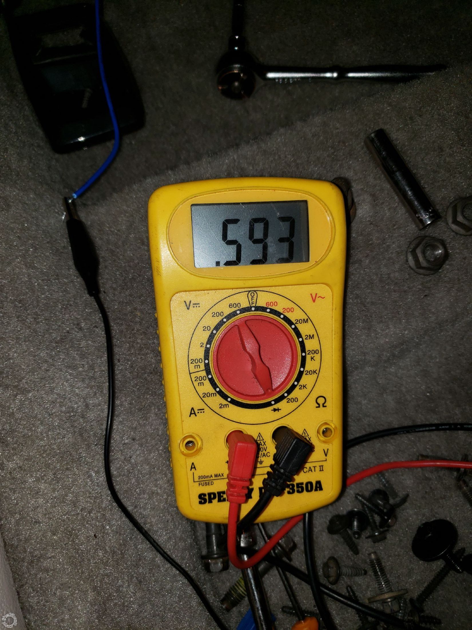
Posted By: kreg357
Date Posted: March 12, 2019 at 7:29 AM
The correct way to use a DMM to check for a (-) output signal is like this ;
DMM set to 20 V DC.
Red test lead to (+) 12 volt constant.
Black test lead to the RKE Trunk output wire.
When the RKE unit outputs the trunk release signal, typically 1.0 second long, the DMM will go from 0v to +12 volts.
-------------
Soldering is fun!
Posted By: nick92
Date Posted: March 12, 2019 at 10:47 AM
Kreg, Thanks for the reply. Last night when I was testing I also did what you suggested and I was not able to read voltage. When I trigger the RKE to open the trunk you can hear the relay in the box actuate, but it doesn't seem to be sending a signal. The RKE was $18 on Amazon. I think I'm going to exchange it. Using the test method I described in my other post I was able to verify continuity triggering the lock/unlock relays. Also when I put DMM on the lock/unlock leads it stays at 1 until you hit the relay then it drops to 0 for a split second. When I do the same thing with the trunk unlock wire it immediately drops to 0.56 and stays there. Any idea why it would do that?
Posted By: kreg357
Date Posted: March 12, 2019 at 11:22 AM
Not sure on that. I don't use continuity to test the controllers outputs.
Are the lock and unlock wires connected to the car during this continuity test?
Is the Truck Release wires connected to anything during this test? That
could explain the difference.
Bottom line, connect the Truck output to a standard 30/40 amp SPDT relay
like this :
+12V constant to Pin 86
RKE (-) Trunk Release output to Pin 85
Make the RKE do a trunk release with its' remote. You should hear/feel
the relay click/energize for a second. You could even use your DMM
continuity test with pins 87 to 30 to verify.
-------------
Soldering is fun!
Posted By: nick92
Date Posted: March 12, 2019 at 1:19 PM
Yes, the lock and unlock wires are connected.
I'm using an alligator clip connected to the DMM and the negative trigger wire of the RKE. The other lead on the DMM is going to chassis ground on the car.
The theory is that if the RKE internal relay is functioning normally and sending a negative trigger when I trigger it with the key fob the relay will close and complete the continuity circuit. This test worked for the lock/unlock relays. When I do this with the trunk wire I get the odd readings.
I wired the relay in as you described. Because the RKE relay tends to make a lot of noise I held the trunk popper relay in my hand and triggered the RKE. It doesn't do anything.
Just to make sure that I had a good relay I grabbed a new one out of the box, I ordered 5, and tried it. Again nothing.
Taking it one step forward I got a few scraps of wire together and wired one of the relays so that it was getting constant 12volts then using another wire I tapped it to ground. The relay fired as expected. This all leads me to believe that my RKE is not functioning properly.
Early in this adventure of keyless entry and trunk popping I wired the door lock actuators wrong and could have send a voltage spike through the RKE control box.
I'm the one asking for help here so again thank-you for you interest in helping and the responses. This is not my strong suit and understand that I could be completely wrong about all of this!
Thanks again, Nick
Posted By: kreg357
Date Posted: March 12, 2019 at 11:19 PM
Your testing is good. It would appear that the (-) Trunk Release Output is no good.
Does the RKE system have an AUX output or a Second Unlock output?
-------------
Soldering is fun!
Posted By: nick92
Date Posted: March 13, 2019 at 9:45 AM
Not one that would be convenient. The key fob only has lock, unlock, and a trunk button. I went ahead and ordered a replacement.
Thanks for the help!
|