I Only Want to Connect/Use Keyless Entry/Exit
Printed From: the12volt.com
Forum Name: Car Security and Convenience
Forum Discription: Car Alarms, Keyless Entries, Remote Starters, Immobilizer Bypasses, Sensors, Door Locks, Window Modules, Heated Mirrors, Heated Seats, etc.
URL: https://www.the12volt.com/installbay/forum_posts.asp?tid=145263
Printed Date: April 18, 2026 at 3:24 AM
Topic: I Only Want to Connect/Use Keyless Entry/Exit
Posted By: horacecain
Subject: I Only Want to Connect/Use Keyless Entry/Exit
Date Posted: February 27, 2019 at 12:44 PM
Hello, newbie.
I purchased a alarm with all the options, a cheap one on eBay. It has the same color wires and parts as all others.
I am trying just to connect it to use the remotes to unlock and lock my doors.
The vehicle does not have power door locks.
This alarm system came with the 4 door lock actuators.
I just need to know how to connect it to use the door lock/unlock features
Thanks in advance
-------------
MR
Replies:
Posted By: i am an idiot
Date Posted: February 27, 2019 at 7:32 PM
Have you removed the door panels to see if you can attach the actuators to the lock mechanism?
Posted By: horacecain
Date Posted: February 27, 2019 at 8:16 PM
Thank you for your response, yes I have removed the panels, I recently replaced all 4 door speakers and each door has access to the rod(s) with out interfering the window rolling up and down.
-------------
MR
Posted By: geepherder
Date Posted: February 28, 2019 at 6:56 AM
https://www.the12volt.com/relays/relaydiagram4.html------------- My ex once told me I have a perfect face for radio.
Posted By: chev104275
Date Posted: March 02, 2019 at 4:49 AM
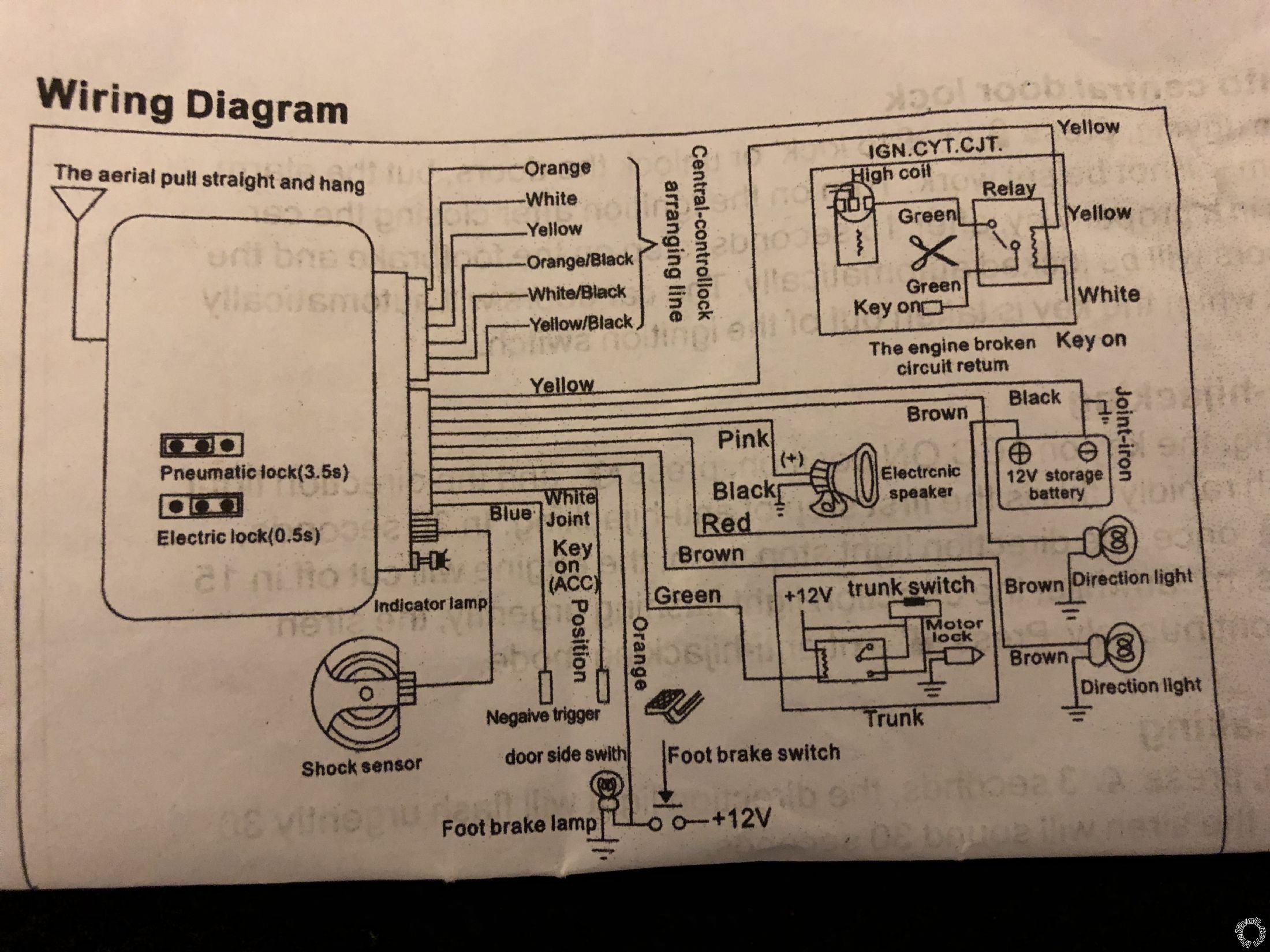
Can you post the wiring f that came with the system ? I would assume if it came with the actuators the diagram would show you how to wire it.
-------------
If i Can't Install it I Don't need it Joe
Posted By: horacecain
Date Posted: March 03, 2019 at 7:40 AM
 ------------- MR
Posted By: i am an idiot
Date Posted: March 03, 2019 at 10:43 AM
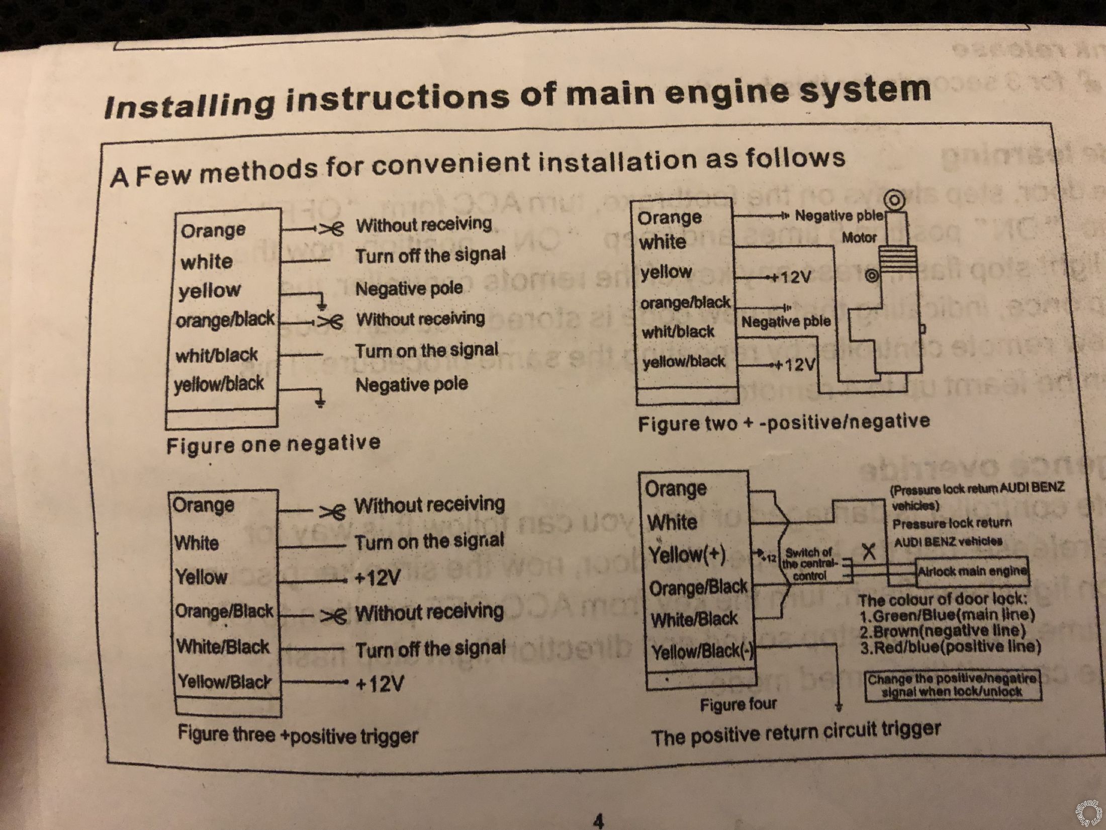
For the door lock portion you need to use figure 2 for the wiring. You do not need to use the relay diagram provided earlier, that diagram is built into your alarm system.
If you are not using any of the alarm features you will connect only the Black Brown and White wires of the system.
And the wires for the door actuators.
Posted By: horacecain
Date Posted: March 03, 2019 at 11:20 AM
Thank you,
Ok refresh:
WHITE goes to Positive source.
BLACK to Negative source.
Where does BROWN go?
If I understand correctly, the driver door actuator has 5 wires on it and is the master the other units have only 2 wires, how do those connect to each other?
I appreciate your help and time.
-------------
MR
Posted By: i am an idiot
Date Posted: March 03, 2019 at 3:16 PM
Brown goes to constant 12 volts. White to an accessory or ignition power source.
Does the 5 wire actuator have a blue and a green wire? If so, use those 2 wires only. Connect all the blue actuator wires together and connect all the green wires together. Wire those as shown in figure 2. White to Blue. White/black to green.
You should also connect the parking light wire so you can count light flashes to make sure it locks from a distance.
If the locks operate backwards, reverse green and blue.
Posted By: horacecain
Date Posted: March 07, 2019 at 3:12 AM
Once again, thank you for your direction.
Unfortunately the actuator will not operate. I tried reversing the white & white/black also, no movement from the actuators.
I suppose there are other wires that need to be connected to something.
-------------
MR
Posted By: geepherder
Date Posted: March 07, 2019 at 3:56 AM
Do you have the orange and orange/black to ground, and yellow and yellow/black to constant 12 volts?
Is the red connected to constant 12 volts and the black to ground?
The brown wire is your positive parking light output.
-------------
My ex once told me I have a perfect face for radio.
Posted By: horacecain
Date Posted: March 08, 2019 at 7:55 AM
Geep,
I am bench testing the unit in doors.
I am using a 12v DC power supply.
When I connect the wiring, I hear the hear unit click. The indicator light supplied stays solid blue.
Nothing happens when I press the remote buttons of the fob. The actuator is connected from the white, white/black to the blue and green wore on actuator.
Perhaps I need to be explained this wiring like I am a baby!
Thank you for your time.
-------------
MR
Posted By: geepherder
Date Posted: March 08, 2019 at 2:24 PM
I honestly can't tell if you are being serious or joking. I meant no offense.
Have you checked for instructions on how to program a remote? It's possible it was lost from programming. If not, contact customer support or the seller.
-------------
My ex once told me I have a perfect face for radio.
Posted By: i am an idiot
Date Posted: March 08, 2019 at 4:41 PM
In figure 2, what did you connect to the yellow and the yellow/black wires?
What did you connect to the Orange and Orange/Black wires?
|