Avital 4105 Install/Troubleshooting, Nissan NV 3500
Printed From: the12volt.com
Forum Name: Car Security and Convenience
Forum Discription: Car Alarms, Keyless Entries, Remote Starters, Immobilizer Bypasses, Sensors, Door Locks, Window Modules, Heated Mirrors, Heated Seats, etc.
URL: https://www.the12volt.com/installbay/forum_posts.asp?tid=145321
Printed Date: May 11, 2026 at 2:41 PM
Topic: Avital 4105 Install/Troubleshooting, Nissan NV 3500
Posted By: aharonhakohen
Subject: Avital 4105 Install/Troubleshooting, Nissan NV 3500
Date Posted: March 28, 2019 at 6:35 PM
Hi All -
I have an IT/low voltage background. I have installed many stereo systems, starters, alternators, emergency vehicle sirens and lights. In other words, I felt comfortable trying to install my own remote start.
The vehicle is a 2016 Nissan NV 3500, standard key.
I had a new in box Avital 4105 sitting around for a couple of years, so I figured I would use that. I purchased an iData Alca, and the smartphone link to program the alca.
Everything is mostly wired up (to-do: hood pin, light flash, brake shutdown). I followed the steps provided by iData to program the key for the bypass.
I am not sure where to begin the troubleshooting process. Here is what happens:
1) When initiating the remote start, the brain will click, the dash lights up, but the engine does not turn over. I figured it has something to do with the key not being properly programmed, so I placed my key on the transponder (the transponder is completely exposed because I removed all of the covering around it). Sometimes, this will remote start the vehicle, but NOT always.
2) I assume this is an unrelated wiring issue, but I will list it, just in case: the lock/unlock on the Avital remote WILL make the brain click. However, the unlock function does not work at all. The lock function sometimes will work, but not always. Even when the lock does not work, the brain still clicks.
I hope I was sufficiently clear. I really appreciate you taking the time to read this post, and thank you in advance!
Replies:
Posted By: kreg357
Date Posted: March 28, 2019 at 8:46 PM
A few questions :
Are you going D2D between the 4105 and the ADS AL-CA? ( using 4 Pin D2D cable and not hardwiring the inter-connections.)
Did you flash the ADS AL-CA with the ADS or DBI flavor of NI4 firmware? You can use either flavor if going W2W but must use DBI if going D2D.
When programming the ADS AL-CA to the van, did you first set the Installation Mode to the proper mode ( Standard or Data ) ?
The ADS AL-CA will provide the van Brake signal, so no need for a manual connection to the van.
The Lock / Unlock issue seems separate. You might want to double check your 4105 Chassis Ground connection.
If would probably help us if you listed all your wire connections.
-------------
Soldering is fun!
Posted By: aharonhakohen
Date Posted: March 28, 2019 at 10:14 PM
Thank you very much for your response.
I originally wanted to use D2D, but a mechanic friend of mine claimed iData and Directed would not work in data mode. I did not really believe him, but I figured I would play it safe. So, it is wire to wire.
I flashed with ADS. When I programmed for the van, I set it two flashes (standard). I then put my key in the ignition, turned to 'on', waited for the led to solid green for two seconds, and removed the key.
Regarding wiring, I should post each wire connection?
Thank you again!
Posted By: kreg357
Date Posted: March 29, 2019 at 5:03 AM
Your friend was wrong. If you flashed it with the DBI flavor of NI4,
D2D would work fine. But going W2W will always work best. Especially
with Data Tach and Brake having occasional issues with some DEI R/S
models.
My initial thought was you flashed it with ADS and went D2D. That would
have accounted for the R/S issues. Being as you went W2W, those same R/S
issues could come from using the wrong signal for the ADS AL-CA GWR input.
Due to the different terminology used by DEI, their GWR signal is called
(-) Status Output. So the 4105's Dark Blue (-) Status Output wire should
be connected to the ADS AL-CA's Blue/White GWR Input wire. ( As a side
note, you can also use the 4105's Blue/White (-) Second Status Output wire
for GWR if you don't need it for the Defrost function and don't change the
factory default programming on that wire.)
While it is a bit of work to list out your wire connections, it will be the
quickest way to assist you. Going W2W is fine with the ADS firmware and
your programming steps were correct. The module should be properly bypassing
the trucks transponder system. Being as the 4105 has no alarm capability,
there will no need to use the Door, Trunk, or EBrake Status signals, nor the
Trunk Release wire. Remember that the Hood Status output will only be
available if the NV has a Factory Alarm system and a hood pin switch.
This will reduce the number of 4105 to ADS AL-CA inter-connections. Here
is a plug list for the 4105 to further simplify making a wiring chart for
your install :
Avital 4105
H1/1 LIGHT GREEN/BLACK FACTORY ALARM DISARM
H1/2 GREEN/WHITE FACTORY REARM
H1/3 YELLOW (+) IGNITION OUT (TO ALARM)
H1/4 WHITE/BLUE (-) ACTIVATION INPUT
H1/5 ORANGE (-) GROUND WHEN LOCKED
H1/6 BROWN (-) HORN OUTPUT
H1/7 RED/WHITE (-) TRUNK RELEASE OUTPUT
H1/8 BLACK GROUND
H1/9 WHITE (+/-) LIGHT FLASH
H2/1 BLACK/WHITE (-) NEUTRAL SAFETY SWITCH INPUT
H2/2 VIOLET/WHITE TACHOMETER INPUT WIRE
H2/3 BROWN (+) BRAKE SWITCH SHUTDOWN WIRE
H2/4 GRAY (-) HOOD PINSWITCH SHUTDOWN WIRE
H2/5 BLUE/WHITE (-) 200mA 2ND STATUS/REAR DEFOGGER OUTPUT
4-pin satellite harness diagram
1 BLUE (-) STATUS OUTPUT
2 ORANGE (-) ACCESSORY OUTPUT
3 PURPLE (-) STARTER OUTPUT
4 PINK (-) IGNITION OUTPUT
Heavy gauge relay wiring diagram
6 PINK (+) (30 AMP) OUTPUT TO IGNITION CIRCUIT
5 PURPLE (+) (30 AMP) OUTPUT TO STARTER CIRCUIT
4 ORANGE (+) (30 AMP) OUTPUT TO ACCESSORY CIRCUIT
3 RED (+) (30A) HIGH CURRENT 12 INPUT
2 PINK/WHITE (+) PROGRAMMABLE OUTPUT FOR ACCESSORY OR IGNITION
1 RED (+) (30A) HIGH CURRENT 12V INPUT
Door lock harness, 3-pin connector
1 BLUE (-) UNLOCK OUTPUT
2 EMPTY NOT USED
3 GREEN (-) LOCK OUTPUT
-------------
Soldering is fun!
Posted By: aharonhakohen
Date Posted: March 29, 2019 at 8:36 AM
I am not by my vehicle now, so I cannot post the wire-outs. Hopefully, later today I will do that.
In the mean time, a quick reply:
There was nothing labeled GWR in the Avital schematics. I just grounded out the GWR. Is that perhaps the cause of my issues? I need to ensure the GWR from the AL-CA (blue/white) is going to Status Output (dark blue) on the Avital?
Also, my mechanic-friend (professionally he is a mechanic, but does many of these installs) said that I do not need the 4-pin satellite harness. Was he wrong about that as well?
Thank you again for all of your time and help!
Posted By: kreg357
Date Posted: March 29, 2019 at 8:55 AM
Yes, you definitely need the 4105 Blue Status out going to the ADS AL-CA GWR wire. This signal tells the bypass module that a R/S is about to happen and to turn on the transponder bypass function.
For your install the 4 pin satellite harness is not needed. You can power the NV ACC2 wire with the Pink/White wire after programming it to Accesory.
-------------
Soldering is fun!
Posted By: aharonhakohen
Date Posted: March 29, 2019 at 12:43 PM
Below is my wire2wire connections:
H1/1 LIGHT GREEN/BLACK FACTORY ALARM DISARM - not used
H1/2 GREEN/WHITE FACTORY REARM - not used
H1/3 YELLOW (+) IGNITION OUT (TO ALARM) - not used
H1/4 WHITE/BLUE (-) ACTIVATION INPUT - not used
H1/5 ORANGE (-) GROUND WHEN LOCKED - not used
H1/6 BROWN (-) HORN OUTPUT - not yet connected
H1/7 RED/WHITE (-) TRUNK RELEASE OUTPUT - not used
H1/8 BLACK GROUND - grounded to vehicle
H1/9 WHITE (+/-) LIGHT FLASH - not yet connected
H2/1 BLACK/WHITE (-) NEUTRAL SAFETY SWITCH INPUT - grounded to vehicle
H2/2 VIOLET/WHITE TACHOMETER INPUT WIRE - al/ca - tach (ac) output - purple/white
H2/3 BROWN (+) BRAKE SWITCH SHUTDOWN WIRE - al-ca - brake status (+) output - green/red
H2/4 GRAY (-) HOOD PINSWITCH SHUTDOWN WIRE - not yet connected
H2/5 BLUE/WHITE (-) 200mA 2ND STATUS/REAR DEFOGGER OUTPUT - not used
4-pin satellite harness diagram - not used
1 BLUE (-) STATUS OUTPUT
2 ORANGE (-) ACCESSORY OUTPUT
3 PURPLE (-) STARTER OUTPUT
4 PINK (-) IGNITION OUTPUT
Heavy gauge relay wiring diagram
6 PINK (+) (30 AMP) OUTPUT TO IGNITION CIRCUIT - vehicle ignition harness - blue
5 PURPLE (+) (30 AMP) OUTPUT TO STARTER CIRCUIT - vehicle ignition harness - yellow
4 ORANGE (+) (30 AMP) OUTPUT TO ACCESSORY CIRCUIT - not yet connected
3 RED (+) (30A) HIGH CURRENT 12 INPUT - vehicle ignition harness - green
2 PINK/WHITE (+) PROGRAMMABLE OUTPUT FOR ACCESSORY OR IGNITION - not used
1 RED (+) (30A) HIGH CURRENT 12V INPUT - vehicle ignition harness - green
Door lock harness, 3-pin connector
1 BLUE (-) UNLOCK OUTPUT - vehicle unlock
2 EMPTY NOT USED
3 GREEN (-) LOCK OUTPUT - vehicle lock
Additionally, the al-ca also has these connections:
1) Immobilizer data vehicle side (white/black) - I cut pin 4 and connected the side that goes to the vehicle
2) Immobilizer data connector side (white/red) - the cut wire from above that goes to the connector
3) Ignition (+) input (pink) - connected to vehicle ignition harness (blue) along with Avital heavy gauge output to primary ignition circuit (pink)
4) Ground (-) input (blue/red) - grounded to vehicle
5) CanH (brown/red) - vehicle OBD pin 6
6) CanL (brown/yellow) - vehicle OBD pin 14
7) Immobilizer data (orange/black) - connected with Immobilizer data vehicle side (number 1 above) which goes to cut pin 4 on Immobilizer
Hopefully I was able to write this clearly.
Regarding GWR (discussed in your post above), the only Status Output I see is on the Satellite Harness, which I was not using. Is that the correct wire? To confirm that wire should be connected to GWR (-) input - blue/white on the al-ca. The wires should NOT be connected to a vehicle ground. Is that correct?
Thank you again!
Posted By: kreg357
Date Posted: March 29, 2019 at 2:20 PM
Correct on the Blue Status Output wire. It should be connected to the ADS AL-CA GWR wire. If you don't want to use the 4 pin Satellite harness and you don't want or need to use the Rear Defrost feature, you can use the Blue/White Second Status wire as the GWR output wire.
You definitely want the ACC1 wire powered so that the vehicles Heater will work. Might also need to power the ACC2 wire with the 4105 Pink/White, too.
Are you running in Tach Mode? Did the Tach learn complete successfully?
You might try a double Unlock pulse to see if that gets unlock working. That's a 4105 programming option. Also test to verify you have the correct wire by putting a DMM on it and turning a key in the drivers door lock cylinder to unlock. Should show a ground.
-------------
Soldering is fun!
Posted By: aharonhakohen
Date Posted: March 29, 2019 at 2:58 PM
Before I reply to your most recent post, let me say this:
I feel like a fool now: For some reason, I had in my head that I needed to double press the * to do a remote start. I realized that I only needed to press once. Remote start is now working (with my original configuration above, i.e. gwr (blue/white) and 4105's ground (black) and neutral safety switch input (black/white) all connected to vehicle ground. Satellite Harness is not used, and status/rear defrogger (blue/white) is not connected (I actually cut it).
It starts up every time, but brake shutoff does not work.
When I remove the al-ca gwr (blue/white) from vehicle ground and connect it to satellite harness (-) 200ma status output (blue) (as you instructed above), remote start still works, but brake shutoff does not. I don't understand why it works in both configurations, but currently I am leaving it as you told me to.
Regarding tach learning, I followed the procedure as outlined in the 4105 installation. Everything seemed like it worked (LEDs blinked when they were supposed to).
Regarding the unlock, I tried the double pulse, to no avail. I have not tried the other suggestions yet. I noticed in the programming of the al-ca the option for the factory remote to work with lock-lock-lock. I set that option, but it does not work. This would bypass the Avital remote unlock issue. Is the factory remote an option, or not worth the trouble?
Thank you!
Posted By: aharonhakohen
Date Posted: March 29, 2019 at 3:03 PM
Oh, and regarding accessory: I definitely want that connected, I am just battling with my ignition harness. I was able to get to 3 out of the 4 wires, but I cannot seem to expose enough of the harness to properly strip and splice. As it is, I can barely get my knife in there, let alone a splicer/stripper and soldering iron. I had to tape everything. It is looking like I might need to take off the entire plastic underneath the gauges...
Posted By: aharonhakohen
Date Posted: March 29, 2019 at 3:12 PM
Sorry for multiple posts...
I believe the brake shutoff problem is solved. I had the wrong wires connected.
But, now I have an extra wire: on the al-ca, E-brake (-) output - green. Where is E-brake status (-) input on the 4105?
Posted By: kreg357
Date Posted: March 29, 2019 at 3:27 PM
Ebrake is not used. It would be necessary for a Manual Trans car install.
Aren't you getting Brake from the ADS AL-CA?
-------------
Soldering is fun!
Posted By: kreg357
Date Posted: March 29, 2019 at 3:35 PM
This is going to get confusing.
Putting the ADS AL-CA Blue/White to Chassis Ground is wrong. It would mean that the transponder bypass function was ON all the time. That should mess up a regular key start and allow a thief with a screwdriver to steal the van. The ADS AL-CA GWR wire should see the ground signal from the 4105 and only when a R/S is called for.
-------------
Soldering is fun!
Posted By: aharonhakohen
Date Posted: March 29, 2019 at 3:42 PM
Understood. Thank you for the explanation.
Posted By: kreg357
Date Posted: March 29, 2019 at 3:42 PM
The ADS AL-CA option for Lock-Lock-Lock has nothing to do with the 4105 and its ability to control the vehicles locks. That option is for certain installs that allow the ADS AL-CA to R/S a vehicle with a Lock-Lock-Lock sequence from the factory remotes. Can't work on your vehicle because the ADS AL-CA does not controll the 4105 and does not directly connect to the main ignition wires itself.
-------------
Soldering is fun!
Posted By: aharonhakohen
Date Posted: March 29, 2019 at 3:47 PM
Understood.
So, my to-do list:
Wire up horn, lights, and acc.
I am probably taking a break until Saturday or Sunday night, and I will update the post then.
Thank you again for the detailed help and information.
Have a great weekend!
Posted By: aharonhakohen
Date Posted: April 03, 2019 at 8:30 PM
Sorry for the delayed update. I attached the acc wire, and have been successfully using it for a few days. The heat and a/c work, but the radio does not turn on until I turn the key. I assume that is by design.
I attached what I believe is the wire for the horn, but I cannot get the remote to make any horn beeps when I lock the vehicle. I am also having difficulty locating the wire for the lights I used wirecolor.com for the wire locations. It states that the wire should be in drivers A-pillar. But the wire colors in the photos do not match up with what I have.
Posted By: kreg357
Date Posted: April 04, 2019 at 5:44 AM
For the Horn, you must change the 4105 default programming. See Menu 1 Feature 1. It comes
set to OFF. You can select the horn output time, typically Option 2 is good.
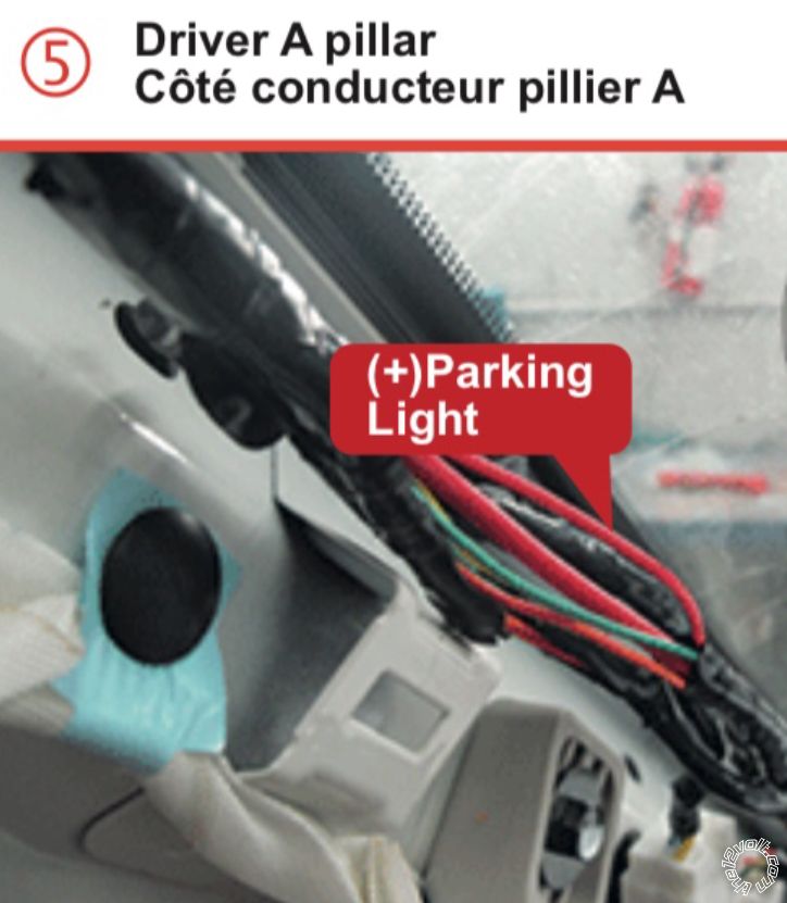
For the Parking Lights, try using this wire :
Parking Lights (+) Red Driver Kick Panel, White 4 Pin connector, Pin 3
Make sure the 4105 Parking Light jumper is set to (+).
If you want the radio and other not too important things to function during R/S run time,
connect the Vipers Pink/White selectable ignition output wire to the trucks ACC2 wire. It
is the Violet wire at Pin 5 of the White 6 pin main ignition switch harness. You must
program the 4105 Menu 3 Feature 6 to Option 2 for this wire to act as an Accessory type wire.
-------------
Soldering is fun!
Posted By: aharonhakohen
Date Posted: April 05, 2019 at 12:34 PM
Regarding the horn, I followed the programming steps (I know everything is connected correctly, because the horn beeps during programming). I think I have it programmed correctly now. When is the horn supposed to honk (locking, I suppose). Any other time? I noticed that if I long press lock, the alarm goes off.
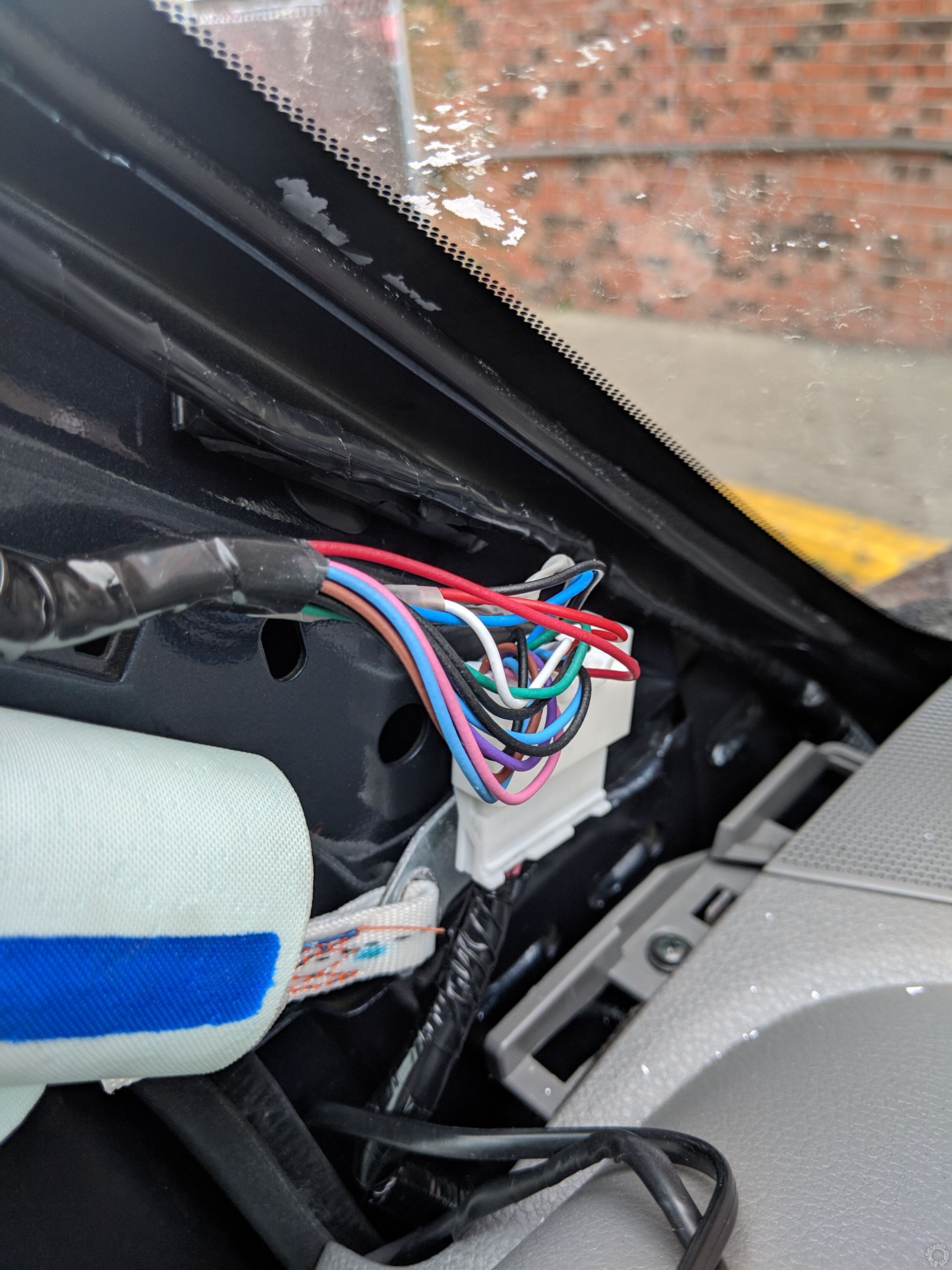
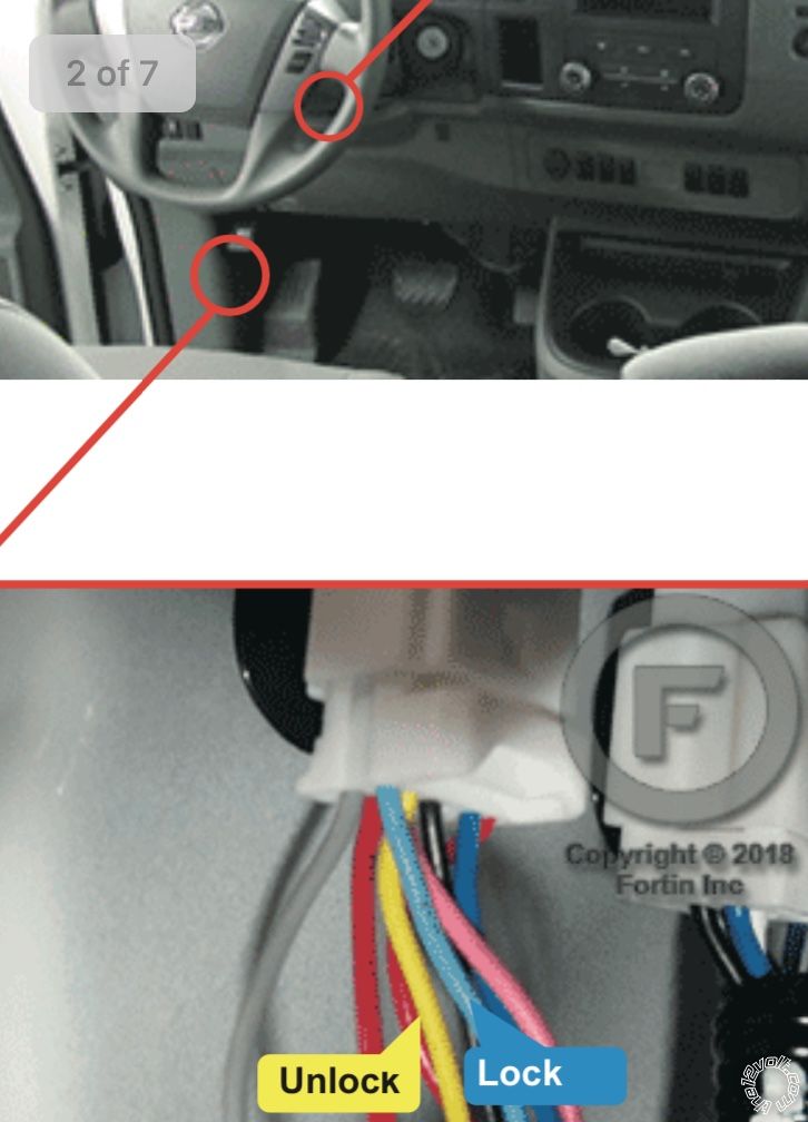
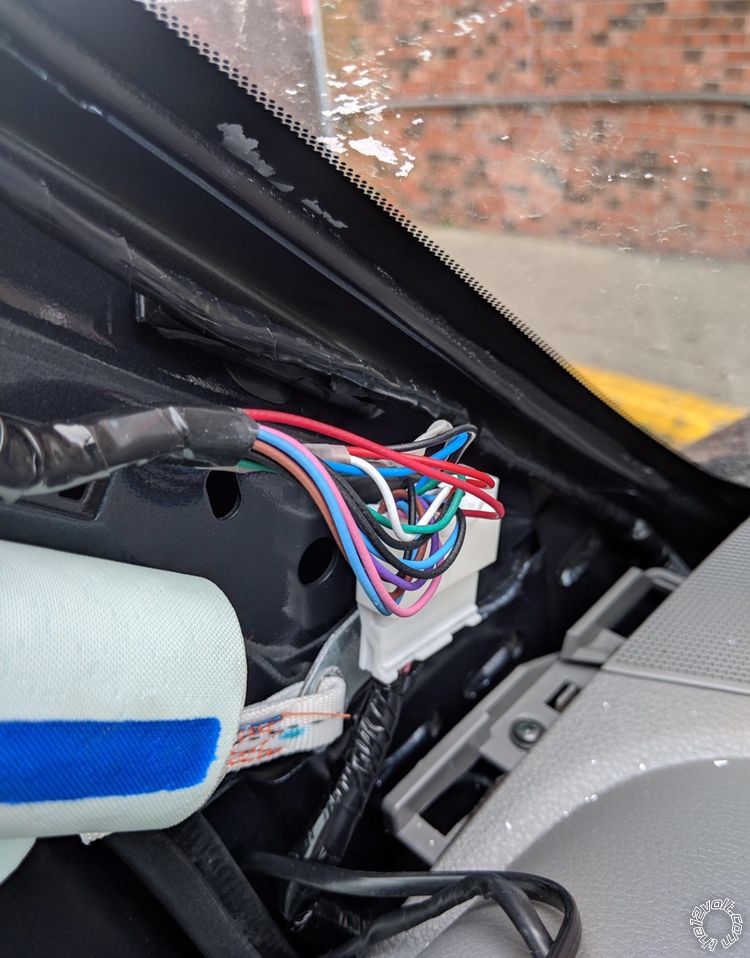
Regarding parking lights, I cannot find such a connector. I have attached pictures both of my kick panel and of my A-pillar.
Regarding, lock/unlock, I am at my wit's end. What I have tested:
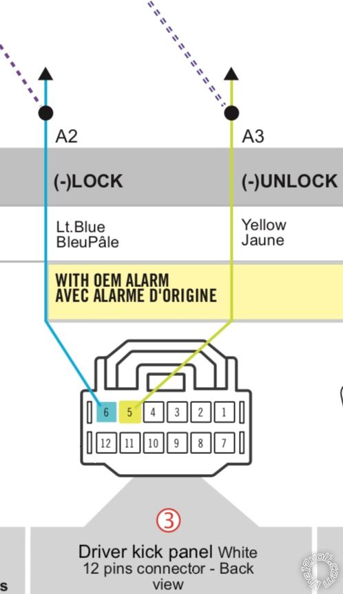
1) On Fortin's website it lists light blue and yellow, as lock and unlock, respectively. On wirecolor.com, it shows gray and red as lock and unlock, respectively. ALSO, it shows light blue and yellow as lock and arm, and unlock and disarm, respectively. I have tried all combinations. I was able to get the lock to sporadically work. I was unable to get unlock to work at all.
2) The brain clicks both when I click lock and unlock, so I know the remote is talking to it.
3) I tested voltage on the pins of the brain (three pin lock/unlock), and also when the plug is in, at the end of the wires (just to make sure that the wire is not damaged). The middle (unused) pin shows constant 12v; the lock and unlock pins show around .6v when the remote is clicked.
4) I also tested voltage on the vehicle's wiring, to ensure that I have the correct wires.
I don't know what else to do. Any troubleshooting steps for me?
Thank you again for your help!
Posted By: aharonhakohen
Date Posted: April 05, 2019 at 12:49 PM
Whoops, forgot the pictures...
Posted By: kreg357
Date Posted: April 05, 2019 at 8:32 PM
It is possible that there is a problem with your 4105 and its' lock outputs. A few thoughts...
The proper way to test for a (-) signal in a normal +12 volt vehicle with a Digital Multimeter is as follows.
Set DMM to 20 volts DC range
Connect Red test lead to +12 volt constant source
Connect Black test lead to suspect wire
When the (-) signal is present, the DMM will show +12 volts. Kind of inverse logic but it works.
As a test, find that vehicle lock wire I mentioned previously that came from the Drivers door lock
cylinder. Connect the DMM and watch it while you insert a key and turn & hold it in the lock position.
The DMM should go from 0 volts to 12 volts with the key turn. The other lock and unlock wires should
do the same thing when triggered by either a door switch button or remote command.
You can also use the DMM to test the 4105s' outputs. If you think they are bad you could use the
4105 Arm or Disarm wires as a test. Even the 4105s' (-) Trunk Release is a possible test to see
if the vehicles wires are correct and working.
Remember that the 4105 clicking with a lock or unlock command is its' internal Parking Light relay.
-------------
Soldering is fun!
Posted By: kreg357
Date Posted: April 06, 2019 at 12:49 PM
According to the 4105 Install Guide, with Menu 1 Feature 1 programmed to anything other
than Option 1, the horn should beep once for Lock. twice for Unlock and if you press and
hold the Lock button for >2 seconds and trigger Panic Mode, it will beep for 30 seconds
unless aborted with a press of the Unlock button.
I don't have a photo of the Parking Light wire. Pretty sure it is in a White 4 Pin
connector in the Drivers Kick Panel area. It could be behind the other connectors
in your photo or up high. Stay away from the Yellow connectors, they are for the air
bags. That White 4 Pin connector might have an Orange wire in it for the Reverse
Lights, too.
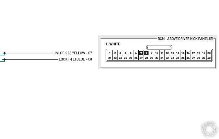
Does your van have the Factory Alarm System? If yes, then you will have to use the
Light Blue and Yellow alarm wires mentioned previously. They can be found at the
BCM in a White 40 Pin plug at Pins 7 and 8. Using the DMM you can test for these
(-) signals using a key in the Driver Door lock cylinder. The BCM is behind the
instrument cluster.
-------------
Soldering is fun!
Posted By: iskidoo
Date Posted: April 06, 2019 at 3:08 PM
aharonhakohen wrote:
Regarding, lock/unlock, I am at my wit's end. What I have tested:
1) On Fortin's website it lists light blue and yellow, as lock and unlock, respectively. On wirecolor.com, it shows gray and red as lock and unlock
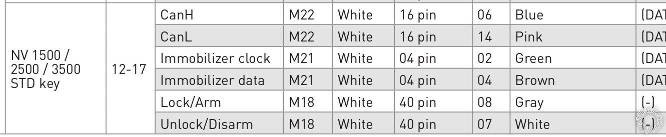
Im seeing (lock/arm) as GRAY at position 8 and (unlock/disarm) and WHITE at position 7 in the 40 pin BCM when looking at the AL-CA wiring chart. Im not sure where Fortin is involved, I found this at idatalink.com. Like kreg357 said use the DMM and test for negative signal when turning driver door key.
Heres the install guide I was referencing.
AL-CA Install Guide------------- Steve G
Posted By: iskidoo
Date Posted: April 06, 2019 at 3:49 PM
aharonhakohen wrote:
Is the factory remote an option, or not worth the trouble?
That could be accomplished once you verify that you have the correct lock wire. You could connect the Avital H1/4 WHITE/BLUE (-) ACTIVATION INPUT to the (-) lock wire of the Nissan.
Then you would need to program the Avital input in Menu 2 at option 5 for 3 pulses as the default is 1 pulse which you dont want.
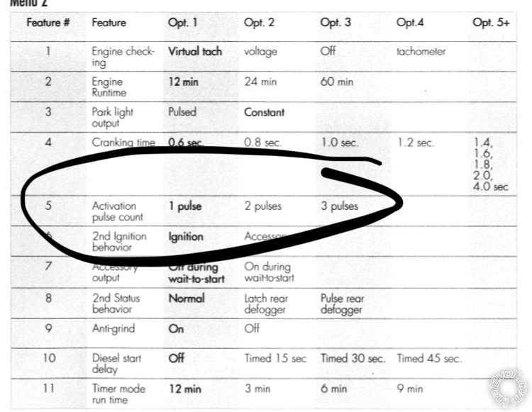 ------------- Steve G
Posted By: kreg357
Date Posted: April 06, 2019 at 4:27 PM
As Steve points out, wiring guide info can be misleading.
It looks like this vehicle might require some extra testing to get the locks to work.
Even iDatalink is providing some possibly conflicting info. While the install guide
for the ADS AL-CA shows the locks as Gray and White, their guide for the HC series
units shows different info.
Going by the ADS-RSA-NI4K-[HC3452A] install guide for the NV3500, provides this info
from Page 239 :
The Light Blue and Yellow wire info matches with the Bulldog, Omega and even DEI's DS4+
info for the Lock/Arm and Unlock/Disarm wires coming from the drivers door lock cylinder.
These conflicts might be due to model year or NV1500/NV2500/NV3500 body styles. The
good news is that they appear consistent with BCM, White 40 Pin connector and Pins 7 & 8.
Even the BCM location varies from "behind the instrument cluster" to "upper driver kick
panel" area. :o): ------------- Soldering is fun!
Posted By: iskidoo
Date Posted: April 06, 2019 at 4:47 PM
Yes I think I may have found what you were referring to when you said Fortin. I see they list yellow and Lt Blue also. They show the photos that seem similar to your posted pics.
 ------------- Steve G
Posted By: iskidoo
Date Posted: April 06, 2019 at 5:00 PM
aharonhakohen wrote:
Whoops, forgot the pictures...
Looks like Fortin indicates that one of those red wires you have in your photo should have the + parking light wire.
 ------------- Steve G
Posted By: aharonhakohen
Date Posted: April 08, 2019 at 5:56 PM
Thank you everyone for the very helpful information above. I just wanted to post to say thank you, and I will hopefully get some time to work on the van, and update the post.
Posted By: aharonhakohen
Date Posted: April 09, 2019 at 4:14 PM
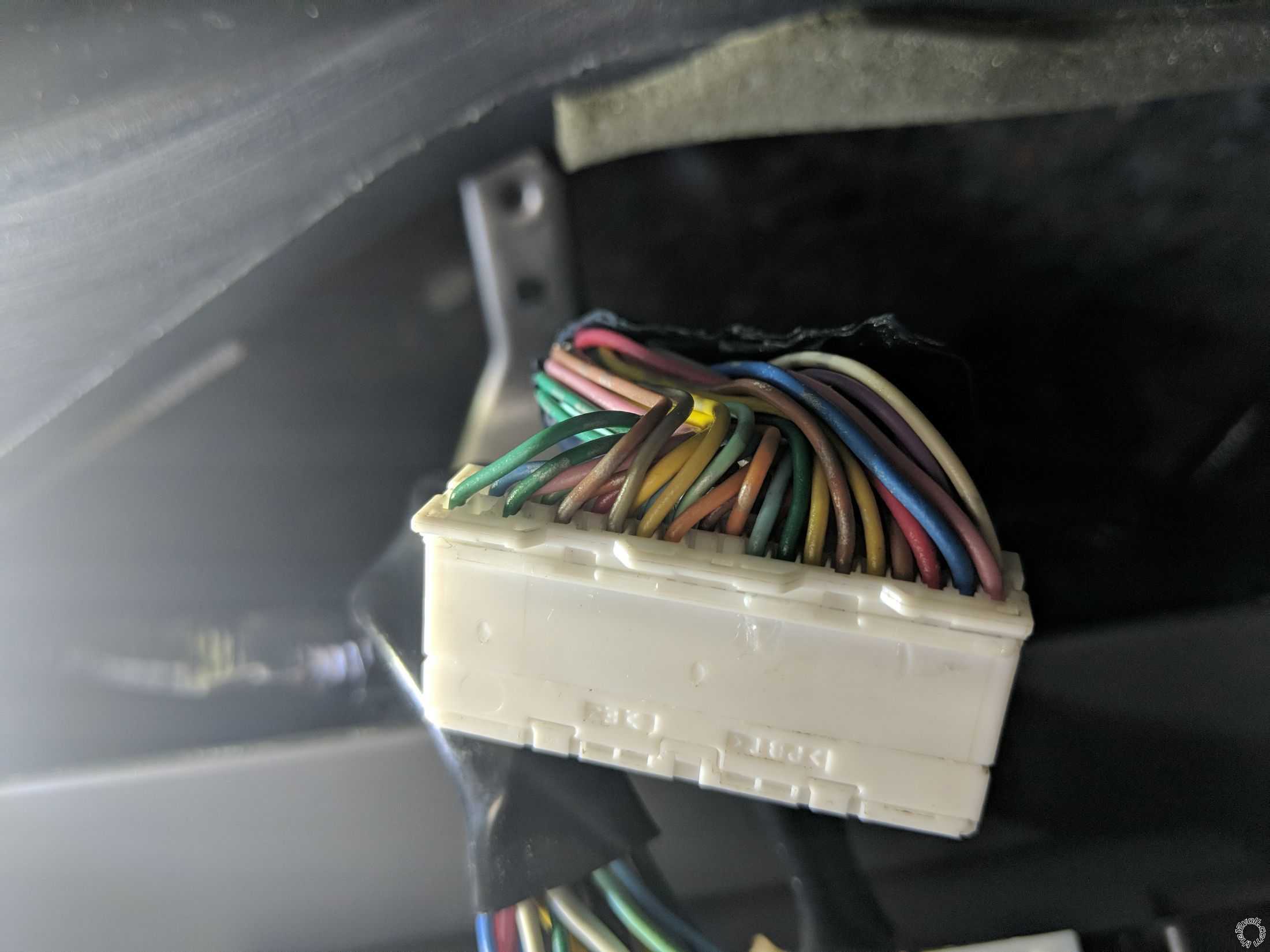
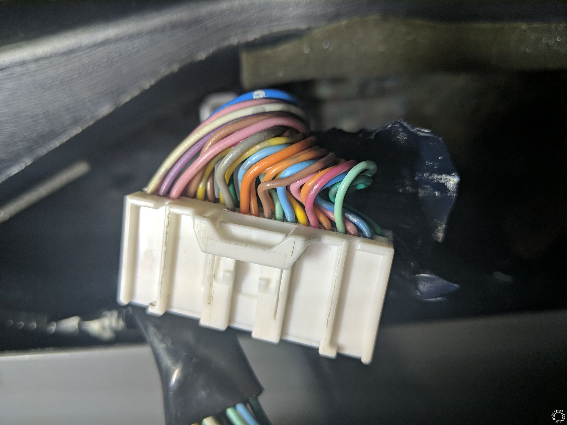
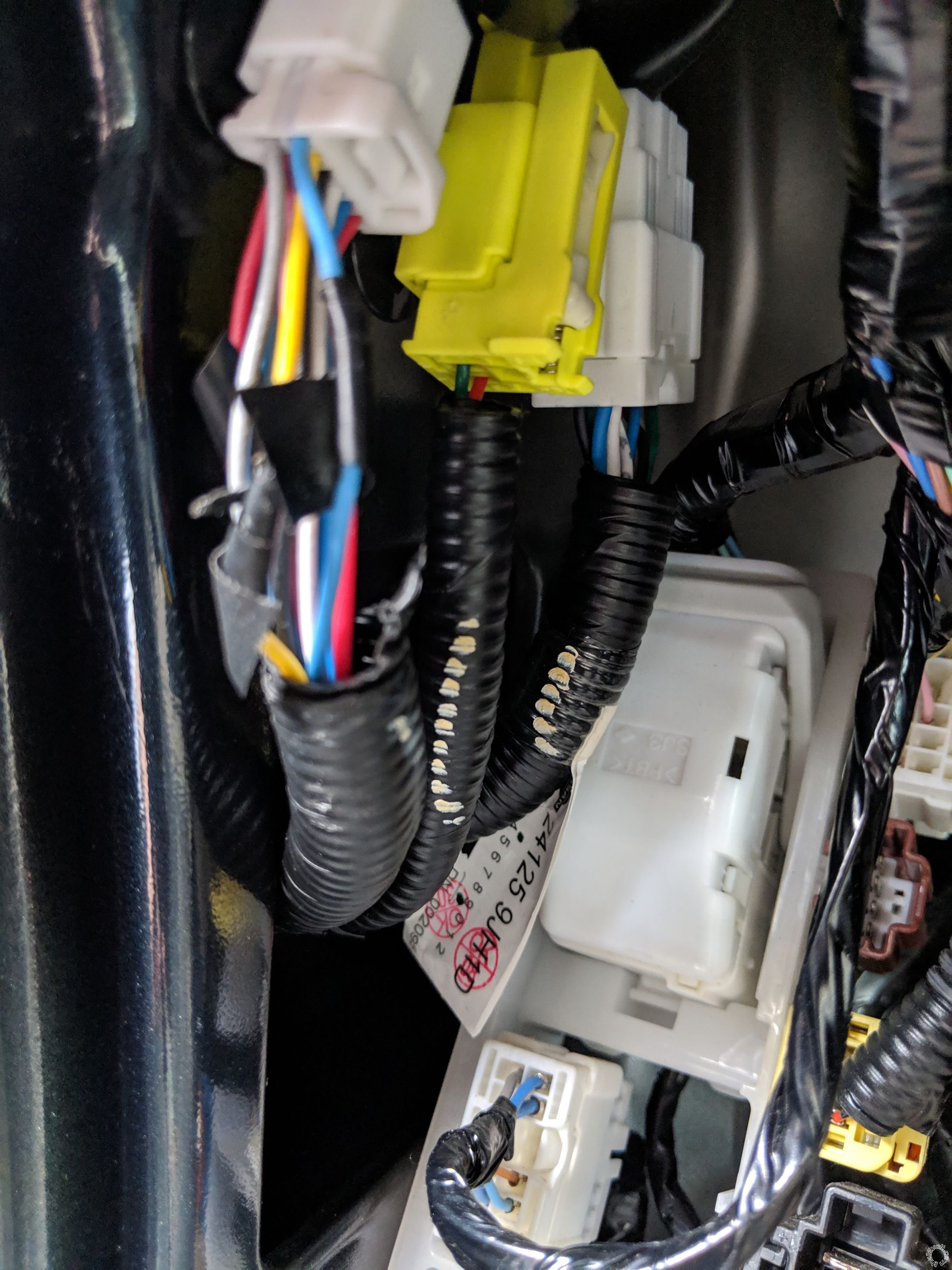
Above are two pictures (both sides) of my 40-pin BCM connector.
I was so intent on using Fortin and Wirecolor for my wire locations (they are much more comprehensive than iData), that I completely forgot about iData's chart that shows CanH, CanL, Immobilizer clock, Immobilizer data, Lock/Arm, Unlock/Disarm. Thank you iskidoo for reminding me.
However, the colors do not seem to match up with iData's install guide (as you can see in the picture). They do match up with Wirecolor. However, Wirecolor does not show the lock/unlock wire positions on the BCM connector. It does show pin 26 is Security LED, which should be cut. Is that applicable to my install?
I am getting ready to test the wires as kreg357 instructed. Does anyone see anything that I am missing?
Thank you again!
Posted By: iskidoo
Date Posted: April 09, 2019 at 4:55 PM
Seems visually that youve confirmed yellow and lt blue at positions 7 & 8 so I guess just verify function with The DMM and you should have lock and unlock squared away. What else are you wondering about?
-------------
Steve G
Posted By: aharonhakohen
Date Posted: April 09, 2019 at 6:43 PM
1. iData's install guide showed pins 7 and 8 (white and gray) on the BCM connector. The problem was that on my connector the colors were not white and gray.
2. Furthermore, on Fortin's install guide it showed pins 1 and 2 (lt blue and yellow) on the driver kick panel 12-pin connector. That was my original connection point. It did not work there.
3. On Wirecolor's diagram, it shows pins 1 and 2 (as Fortin does above), but labels them "lock and arm" and "unlock and disarm" respectively. It also lists grey and red on the same connector as "lock" and "unlock" respectively. I (thought I) had tried this last option, and it did not work. But, I connected it tonight, and it works (almost perfectly)! So, in conclusion: regarding lock/unlock in my 2016 Nissan NV 3500, the correct wires I am using are: on the 12-pin connector by the driver kick panel - grey/lock and red/unlock.
Two things I am noticing:
1) When I unlock using the OEM remote, the first unlock only unlocks the driver door, the second unlock will unlock everything else. Is there any way to have this feature?
2) I am still not getting the horn when I am locking using the Avital remote. I thought that I had changed the programming, but I will try again.
Regarding the wire for the lights in the driver A panel: I noticed that the colors if the wires were different than shown in Wirecolor's pictures. I did not want to start stripping wires just to test if they are the correct wire. But seeing as I have no other choice, that is what I will do.
Thank you!
Posted By: iskidoo
Date Posted: April 09, 2019 at 9:48 PM
So Id go with gray and red but Id also verify that if you arm and lock it with your factory remote, that it doesnt set off the factory alarm when you remote start from the aftermarket remote. Check this by locking and arming and then waiting a few minutes. Then using the aftermarket remote to attempt a remote start. If it starts without issue then thats good. If it sets off the alarm you may need to wire up a factory alarm disarm wire.
Progressive unlocks are always difficult to replicate but it can be done. It usually involves going into the driver door and wiring up the primary unlock wire to only that door lock motor, then wiring the progressive 2nd unlock wire to the vehicles regular unlock wire to pick up all of the other doors. I usually dont bother because of the extra relay and wiring involved.
As far as the horn, if you try different settings in the Avital programming and still dont get the horn honks, maybe check that the bypass isnt disabling the honks. Check through the programming options in there to see if there are some horn honk settings that may be conflicting between the two units.
I wouldnt go crazy with the strippers. I usually just take a utility knife and run a small slit into the plastic insulation of the target wire to get down to the copper. Then just give a slight bend in the wire at the slit so you can poke your DMM probe in and touch the wire. If its the right wire then strip the insulation back enough to solder your wire on. If its not then just bend it back straight and put a small piece of 3M tape to cover up the slit you made. Another good probe tool to have has a grooved channel with a spring loaded sharp probe tip. Makes testing wires much easier.
-------------
Steve G
Posted By: danwcope
Date Posted: December 31, 2019 at 12:19 PM
OP,
Did you ever figure out the parking light wire? I'm having a hard time locating it in my 2018 NV Passenger Van for my iDatastart module.
Thanks,
Dan
Posted By: aharonhakohen
Date Posted: January 17, 2020 at 8:07 AM
The short answer is, yes. But, I have no recollection of which wire it was.
I completed the installation, and everything has been working for a while already.
Sorry I could not be more help.
Posted By: djdeito
Date Posted: February 03, 2020 at 3:10 PM
2016 Nissan NV 3500
Parking light (+)
Color: Red
Polarity: Positive
Location:
Driver's kickpanel, White 4 Pin plug, pin# 3
make sure to test this wire using a digital multimeter.
|