Viper 5305V Trunk Release Negative Output Problem, 1990 Ford Mustang
Printed From: the12volt.com
Forum Name: Car Security and Convenience
Forum Discription: Car Alarms, Keyless Entries, Remote Starters, Immobilizer Bypasses, Sensors, Door Locks, Window Modules, Heated Mirrors, Heated Seats, etc.
URL: https://www.the12volt.com/installbay/forum_posts.asp?tid=145426
Printed Date: May 12, 2026 at 7:42 AM
Topic: Viper 5305V Trunk Release Negative Output Problem, 1990 Ford Mustang
Posted By: redfox90
Subject: Viper 5305V Trunk Release Negative Output Problem, 1990 Ford Mustang
Date Posted: May 21, 2019 at 7:53 PM
I recently installed a viper 5305v unit in my 1990 Mustang lx. I successfully was able to wire it up correctly and everything works great(locks, alarm, starter kill). My problem is the trunk release is not working no matter what I do. My car does have a factory switch for the trunk release and applying 12v to the purple and yellow wire on my factory harness will pop the trunk. I understand that the viper alarm has a red/white wire which is used for a trunk release and is a 200ma negative output. Using a 30/40 SPDT relay I tried every configuration and I cannot get a response powerful enough out of the viper system to trigger the relay. Using a cheap multimeter when I hold down the aux button on the remote it does show that it is pulsing but it doesnt seem like it is enough. I am getting very low readings. On the 200m setting of the multimeter the highest pulse that I got while holding the aux button for a few seconds was 80.6. I tried multiple wiring techniques for the relay and none will trigger the trunk no matter what I do. I understand how relays work but for the life of me I cant figure it out. I am unsure if I need to program another aux channel and use that for the output instead? I havent messed with the settings on the 2 way remote at all. I am lost at this point. When wiring the relay I used:
pin 85 as 12v constant fused power
Pin 86 as 200ma negative output from alarm
Pin 87 as ground
Pin 30 as 12v output going to switch for trunk
Pin 87a not in use
I tried also switching pin 87 ground for 12v constant power as well connecting together with pin 85 and I cannot get a response from the system at all. The negative output from the alarm does not ground enough to bridge the relay. Relay has been tested and works. What should I try next or test? Any help would be greatly appreciated.
Replies:
Posted By: eguru
Date Posted: May 21, 2019 at 9:14 PM
The multimeter is probably not able to display the actual peak current since the pulse is only about 500 milliseconds. Are you certain that the relay contacts are not closing? Is your factory switch provide ground to the trunk release solenoid or +12V?
Posted By: redfox90
Date Posted: May 21, 2019 at 10:09 PM
Yeah the relay is not closing at all. I took off the trigger wire from the alarm and added a chassis ground to it and the moment that happens the relay clicks. Put the negative output wire from the alarm and hold the aux button and nothing. The factory switch is just providing 12v and the trunk pops. Theres actually two wire pink/white with 12v constant on the bottom of the trunk switch and when you click the button 12v gets applied to the purple and yellow popping the trunk
Posted By: geepherder
Date Posted: May 22, 2019 at 2:12 PM
Measure the resistance of the relay coil. The typical range is around 70-80 ohms. If you get a reading much lower than that, try a different relay.
Also try one of the aux outputs as you suggested. Connect either terminal 85 or 86 to constant power and the remaining terminal to your aux output.
As long as the relay clicks, you can wire 30 and 87 to the wires at the back of the switch. It doesn't matter which side is which.
-------------
My ex once told me I have a perfect face for radio.
Posted By: redfox90
Date Posted: May 22, 2019 at 2:52 PM
Just measured the resistance of the coil and got 88.7. Also applied 12v and ground and was able to get it to click so I want to assume its good. Also have another relay that was brand new and tried that as well but the results were the same.
I messed with it more today and I used the aux 4 output that supplies the same 200ma negative output with no success either. Factory manual states that this channel should be pulsing as long as the command continues. Tried to wire it a few different ways holding the aux button for different time frames to see if anything changes and no dice.
I am starting to think that I have a bad unit, its just strange that everything works except for the trunk release. I opened up the brain of the alarm to peak at the internals and nothing looks damaged or burnt. Not sure what I can do at this point?
Posted By: i am an idiot
Date Posted: May 22, 2019 at 3:52 PM
Do you have an LED and a 1k resistor laying around? Connect the resistor in series with the LED. Power the appropriate leg of the LED, connect the resistor to the negative leg of the LED, connect the other end of the resistor to the alarm output wire in question. If the alarm wire has enough current capacity to illuminate the LED we can make this work with a single transistor and possibly a heat sink. Let me know if it lights up and I will find you a diagram.
Posted By: eguru
Date Posted: May 22, 2019 at 6:36 PM
For just driving the trunk release solenoid, a 10A miniature relay should do the job.
Typically they have a 400 ohm coil. So your output would only need to sink about 35mA max.
If it can do that, it is a lot simpler than adding a relay driver circuit.
Posted By: geepherder
Date Posted: May 22, 2019 at 8:28 PM
Those are both great ideas.
I think the source of your problem is a poor ground. How is the unit grounded/where? Address that, and it should work as designed.
If you have a jumper wire with alligator clips, connect from your current ground point to the rim of the cigarette lighter socket (or any other known good ground). Then try the trunk release via remote.
-------------
My ex once told me I have a perfect face for radio.
Posted By: redfox90
Date Posted: May 22, 2019 at 10:03 PM
Wasnt able to work on it anymore today but I do have some resisters and I will see if I have an led light to try that on hopefully tommorow.
Im gonna also try to locate a 10A miniature relay locally just in case as well as an alternative. That would be great if I could get that to work
The ground for the alarm is a strong chassis ground in the driver side kick panel. I did try using a ground going directly to the battery but there wasnt a change in the results. I can try it again just to verify.
I will post some updates tommorow thanks for everyones input I really appreciate it
Posted By: redfox90
Date Posted: May 23, 2019 at 10:36 AM
Little update, I was able to wire a 1k resister in series along with an led and using the output wire from the alarm and I was able to get the led to light up. It didnt light up very bright but it did light up. It wasnt a single led tho it was 7 leds built in to one so possibly thats why it didnt light up fully.
How would I wire it if I wanted to use a resistor?
As for the relay I ended up ordering a 10a mini relay and it will be here tommorow. I will be attempting to wire it again and see if I can get it to work.
Posted By: eguru
Date Posted: May 23, 2019 at 12:15 PM
If you find that the miniature relay works ok electrically and are looking for a way of mounting it, I have a suggestion.
You can epoxy the top side of the relay to your Viper case - that has worked well for me when it is just 1 or 2 outboard relays.
Posted By: geepherder
Date Posted: May 23, 2019 at 2:09 PM
If you want to go the transistor route, you need a PNP with a gain (hFE) of 20 or more. It only needs to be rated for 200 mA of current or so since it's just triggering a relay.
Connect your 1000 ohm resistor from the Viper's output to the base. Connect fused constant power to the emitter. Connect one of the relay's coil terminals (85 or 86) to the collector and ground the remaining coil terminal. Connect terminals 87 and 30 to the opposite sides of the trunk release switch.
-------------
My ex once told me I have a perfect face for radio.
Posted By: i am an idiot
Date Posted: May 24, 2019 at 5:06 AM
https://www.the12volt.com/installbay/forum_posts.asp?tid=114792&KW=2n6491#556471
Very old post. Radio Shack is no longer an option for the transistor but I am sure you can locate one.
Posted By: redfox90
Date Posted: May 25, 2019 at 6:27 PM
Well not the update I would have wanted to post but I recieved the mini 10a relay that I ordered and before attempting anything I made sure it worked and it does. Moving on to wire it accordingly to get the trunk to pop it did the same thing as all the other relays Ive tried, nothing. I dont get it, I tried wiring it all sorts of ways and I even tried to tie in the previous installed grounds from the viper alarm to other strong grounds on the car and it didnt make any difference. The negative 200ma output is just too weak. No matter what I tried I couldnt get the relay to click using my alarms negative output. Im gonna attempt to buy a transistor and wire it up but honestly its just looking like my trunk pop will never work right with my current alarm.
Posted By: geepherder
Date Posted: May 26, 2019 at 6:38 AM
Out of curiosity, what is the coil resistance of your mini relay? There are different types available. Do you have a link?
It will work with a transistor- even if you have to use a Darlington.
-------------
My ex once told me I have a perfect face for radio.
Posted By: i am an idiot
Date Posted: May 26, 2019 at 7:53 AM
If it is lighting an led, the diagram I posted will definitely work. All the transistor needs is the sight of ground to work.
Posted By: redfox90
Date Posted: May 26, 2019 at 9:15 AM
So I just measured the coil resistance and its showing 125 ohm. The link to the relay: https://www.amazon.com/HELLA-965453041-Micro-SPDT-Relay/dp/B000VU9A28
As for the transistor I am currently trying to find the correct one for this application and will be trying to wire it as suggested. With just the output and the resistor, and 12v constant power It does light up the led but very very dim. Hopefully the transistor can solve my problem.
Posted By: geepherder
Date Posted: May 26, 2019 at 2:34 PM
redfox90 wrote:
So I just measured the coil resistance and its showing 125 ohm. The link to the relay: https://www.amazon.com/HELLA-965453041-Micro-SPDT-Relay/dp/B000VU9A28
That's your issue with the relay. The type eguru referred to have pins on the bottom so they can be soldered to a circuit board and the coils are around 400 ohms. Something like this:
https://www.electronicsurplus.com/omron-g5le-14-12vdc-relay-power-spdt-10a-12vdc?_vsrefdom=adwords&gclid=EAIaIQobChMIsuOz_va54gIVaP_jBx06IQgqEAkYBCABEgK_g_D_BwE
redfox90 wrote:
As for the transistor I am currently trying to find the correct one for this application and will be trying to wire it as suggested. With just the output and the resistor, and 12v constant power It does light up the led but very very dim. Hopefully the transistor can solve my problem.
Just go with the diagram IAAI posted and you don't even need a resistor because of the placement of the relay coil. It doesn't have to be that transistor as long as it's a PNP.
------------- My ex once told me I have a perfect face for radio.
Posted By: redfox90
Date Posted: May 26, 2019 at 11:03 PM
Ok just ordered the relay from the link you posted. Do I wire it up the same as the other relays Ive tried? Also ordered a pnp transistor and will be trying that as well as a worst case scenario. Will take a few days for me to receive them but I will be posting back with the results as soon as I get them thanks everybody for the help
Posted By: geepherder
Date Posted: May 27, 2019 at 4:04 AM
It'll be similar, but the terminals have different designations. Looking at the datasheet, the coil uses terminals 2 and 5 (instead of 85 and 86). The normally open contacts are 1 and 3 (like 30 and 87). If it has a terminal 4 it is not used (like 87a).
If you use a PNP, make sure to note which lead is which. If you ordered one of the part numbers listed in the linked post you should be good to go. Different models may have them oriented differently. If the leads are not clearly indicated on the package, I'd just Google the part number followed by datasheet.
Let us know if you need any more help.
-------------
My ex once told me I have a perfect face for radio.
Posted By: redfox90
Date Posted: May 31, 2019 at 2:07 PM
Ok so update, I recieved the transistors(2n3906) and the relay in the mail. After connecting everything as mentioned it still doesnt work. With just positive and ground between terminals 2(85) and 5(86) I can get the relay to click. But here is where the issue is:
As I set it up:
-Alarm output wire ties into a 1k resistor and the resistor goes into the B leg of the transistor.
-Chassis ground goes to leg C of transistor
-Leg E of transistor goes to 2(85) Of the relay
- Relay #5(86) is 12v fused hot
-Relay #1(30) tried both 12v hot and extra ground separate attempts
-Relay #3(87) goes to trunk release switch wire
The Alarm output wire will not ground enough still to trigger the relay. I tried testing other aux output wires on the viper alarm and none of them work. Sure enough the red and white wire is the only output that works when I press the button on the remote and it sends a signal. One thing to note is that with just testing terminal 85 with a multimeter on dcv before, resting terminal 85 with my original attempt was 12v and while pressing the six button it only would dip down to 11.56v. That was measuring the negative output wire and how much it would ground. Now with the resistor and the transistor it goes from 12v resting to 6.30 with the aux button pressed which means it is working pretty good but not enough. Taking a ground wire from the chassis and touching terminal 85 will make it click instantly so that tells me that the transistor is still not helping enough to ground the input wire and trigger the relay. I have multiple transistors would wiring up another one help to strengthen th power of the negative output wire? I dont know what to do at this point?
Posted By: geepherder
Date Posted: May 31, 2019 at 2:23 PM
You don't need the 1000 ohm resistor because of the placement of the relay coil in the circuit. Do away with the resistor and post back your results.
In other words, connect the Viper's output directly to the base.
-------------
My ex once told me I have a perfect face for radio.
Posted By: redfox90
Date Posted: May 31, 2019 at 2:37 PM
I tried it without the resistor and same result. Its still doesnt work. The moment I introduce a ground to terminal 2(85) the relay triggers and the trunk pop works. But using the aux button on the remote it wont pop on its own. The output wire isnt grounding enough
Posted By: i am an idiot
Date Posted: May 31, 2019 at 4:12 PM
Leave the transistor as it is and apply ground to the Base connection, does that energize the relay?
Posted By: redfox90
Date Posted: May 31, 2019 at 4:29 PM
Yes applying ground directly to the base which also has the alarm output wire will get it to trigger
Posted By: geepherder
Date Posted: May 31, 2019 at 4:52 PM
You can use a Darlington PNP in place of your current transistor. Instead of a gain (hFE) of say, 20, it may have a gain of 1000.
-------------
My ex once told me I have a perfect face for radio.
Posted By: redfox90
Date Posted: May 31, 2019 at 4:58 PM
Is there any way to get it to work with what I currently have? I have 8 more of the 2n3906 transistors. If not can someone post a link to the exact transistor that I need? I just want to be done with this thing already.
Posted By: geepherder
Date Posted: May 31, 2019 at 5:18 PM
If you have more, you can connect two together to form your own Darlington pair. You will still need some resistors. You might get away without the diode, but I'd still recommend it.
Here is an equivalent circuit from a darlington PNP datasheet:
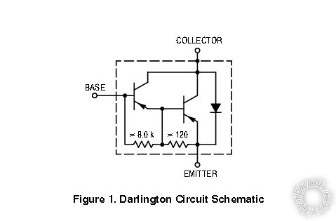 ------------- My ex once told me I have a perfect face for radio.
Posted By: redfox90
Date Posted: May 31, 2019 at 5:28 PM
I dont completely understand that schematic. I have looked up that basically the collectors go together and the emitter from one goes to the base of the other. As of rn I only have 1k resistors, Im looking at the darlington pnp transistors Would this one work?
https://www.amazon.com/Pieces-TIP120-Power-Darlington-Transistors/dp/B00NAY1IBS/ref=mp_s_a_1_1/136-9742292-0919728?ie=UTF8&qid=1559341198&sr=1-1&pi=AC_SX236_SY340_QL65&dpPl=1&dpID=51XDgj8f2uL&ref=plSrch
Posted By: geepherder
Date Posted: May 31, 2019 at 5:46 PM
Sorry. Yes, that's basically correct.
A TIP120 is an NPN. You need a PNP. A TIP125 would be a PNP equivalent and should work. I don't know if you have a Fry's near you, but you can just search for "darlington". Then see which one's are PNP.
-------------
My ex once told me I have a perfect face for radio.
Posted By: redfox90
Date Posted: May 31, 2019 at 6:11 PM
If I did wire up 2 of the transistors I have just to see if it works temporarily which transistor should I hook up the wires to? The first or the second? I understand that the first one sends the power into the second one and it basically gets amplified/increased when it comes out of the second. Would both transistors get grounded or no?
I was able to find the Tip125 Pnp transistor and Im gonna order it if I cant get my current ones to work.
Posted By: geepherder
Date Posted: May 31, 2019 at 6:31 PM
You can try, but I don't think it will work properly without the right resistors. I've modified the picture so it's a little easier to understand. The only wire that connects to Q1 (or the first transistor) is the output from the Viper to the base. The collectors will be connected together, as you said and grounded. The emitter of Q2 (the second transistor) goes to the relay coil, the other end of which goes to positive 12 volts.
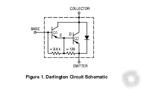 ------------- My ex once told me I have a perfect face for radio.
Posted By: redfox90
Date Posted: May 31, 2019 at 6:36 PM
Ok thanks, thats way easier to understand now. Im gonna try to do that this weekend and post an update. Either case Im gonna just order the other transistor as well, as a backup
Posted By: catback
Date Posted: June 01, 2019 at 1:15 PM
Sounds like you have a bad ground or a bad module. All the aux outputs are capable of triggering any general automotive electrical relay. Make sure you have a solid ground that can carry current. If you have a good solid ground and good power and the problem persists, get the viper replaced if possible because it's defective.
Posted By: redfox90
Date Posted: June 07, 2019 at 11:48 AM
Well update, after receiving the darlington pnp transistor and having no luck I began testing aux output wires and to my surprise I was able to locate an aqua blue/black wire that was able to trigger the trunk with the help of the relay, pnp transitor and a 1k resister. After securing everything my trunk pop now works. I want to thank everyone that helped me to figure this issue out.
Posted By: jim2467
Date Posted: June 26, 2019 at 6:21 AM
Redfox90,
I was just reading some of your posts. May I ask how you wired your remote start? The Remote Start, 10-pin heavy gauge connector? I purchased the Python 5305P which is made by DEI, which makes Viper also. The wiring is pretty much identical. I think that the Red/Black, Red, Red/White wires go to a 12v (+) constant. And I think a 12v (+) constant with a 20 amp fuse should go to pin 87 on a relay. And the #21 pin in the 24 pin harness which is Violet/Yellow 200mA (-) starter output goes to pin 85 on a relay or a chasis ground could be used on the pin 85 or both can be used together on pin 85. And I think that the #7 pin in the 10 pin harness which is the Violet (+) starter output (car side of the starter kill) wire goes to pin 86 on the relay. I think that the #4 pin on the 10 pin harness the Pink/White 2nd ignition/accessory relay output wire goes to pin 30 on a relay. I am just not sure about the pin 6 green starter input (key side of the starter kill wire) in the 10 pin harness and where to connect it and the #8 pin orange (+) accessory output wire in the 10 pin harness and the #10 pin Pink ignition 1 input/output wire in the 10 pin harness. I have the remote keyless entry and the alarm working perfectly and flawlessly. I just cant get the remote start to work. I have a 1993 Ford Bronco 5.8 liter 4x4 Eddie Bauer's Edition. I have the wiring diagram for my Bronco and wire color codes and the Python 5305P install wiring diagram. Any help would be greatly appreciated. 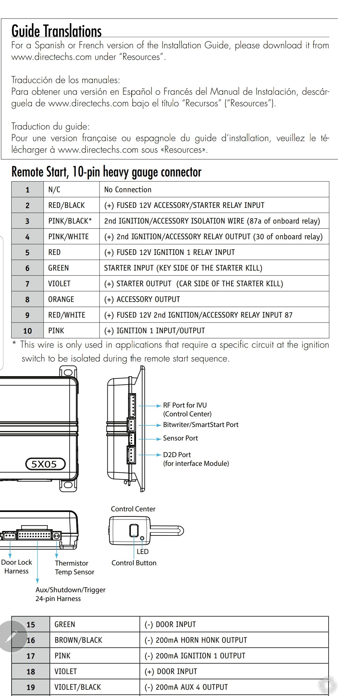  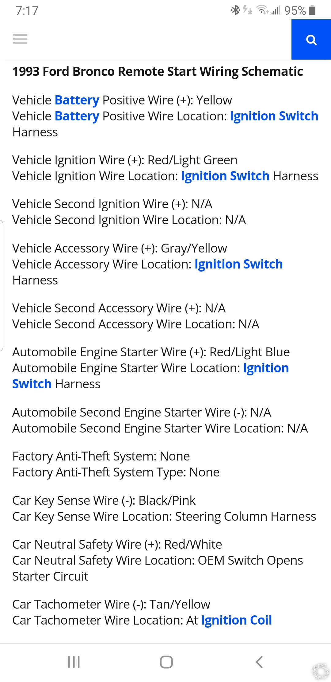 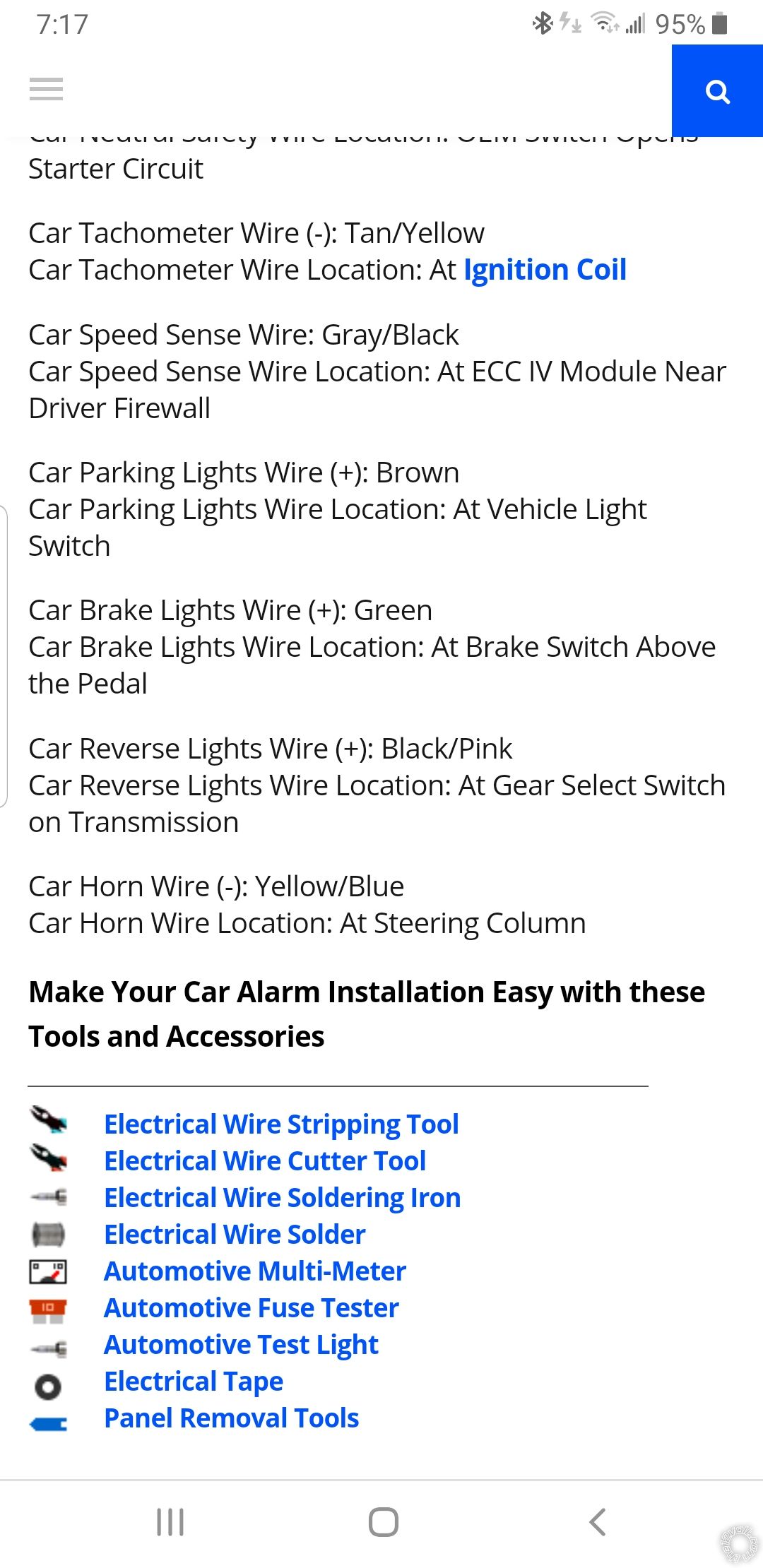 ------------- Signature preview
Posted By: catback
Date Posted: June 26, 2019 at 11:06 AM
jim2467 wrote:
Redfox90,
And I think a 12v (+) constant with a 20 amp fuse should go to pin 87 on a relay. And the #21 pin in the 24 pin harness which is Violet/Yellow 200mA (-) starter output goes to pin 85 on a relay or a chasis ground could be used on the pin 85 or both can be used together on pin 85. And I think that the #7 pin in the 10 pin harness which is the Violet (+) starter output (car side of the starter kill) wire goes to pin 86 on the relay. I think that the #4 pin on the 10 pin harness the Pink/White 2nd ignition/accessory relay output wire goes to pin 30 on a relay.
What's with all the relays? The 10-pin remote start harness should have direct connections to the appropriate wires in the vehicle. No external/additional relays required for the remote start harness.
|