Viper 211HV, Actuator Wiring with No Locks on 73 Trans Am
Printed From: the12volt.com
Forum Name: Car Security and Convenience
Forum Discription: Car Alarms, Keyless Entries, Remote Starters, Immobilizer Bypasses, Sensors, Door Locks, Window Modules, Heated Mirrors, Heated Seats, etc.
URL: https://www.the12volt.com/installbay/forum_posts.asp?tid=145596
Printed Date: May 15, 2026 at 6:14 AM
Topic: Viper 211HV, Actuator Wiring with No Locks on 73 Trans Am
Posted By: jlutz455
Subject: Viper 211HV, Actuator Wiring with No Locks on 73 Trans Am
Date Posted: August 26, 2019 at 1:34 PM
Hi..I'm new to the forum and installing this alarm on my 73 Trans Am that didn't come with power locks so I have no power lock switch and don't plan on adding one.
I've added actuators in the doors and the instructions say this alarm has internal relays and can drive actuators directly. I'm not sure which wires to hook up to the actuators in this case.
Thank you!
Jeff
Replies:
Posted By: iskidoo
Date Posted: August 26, 2019 at 4:03 PM
Post some instructions so we can see the wires listed.
-------------
Steve G
Posted By: jlutz455
Date Posted: August 26, 2019 at 4:31 PM
Posted By: iskidoo
Date Posted: August 26, 2019 at 5:46 PM
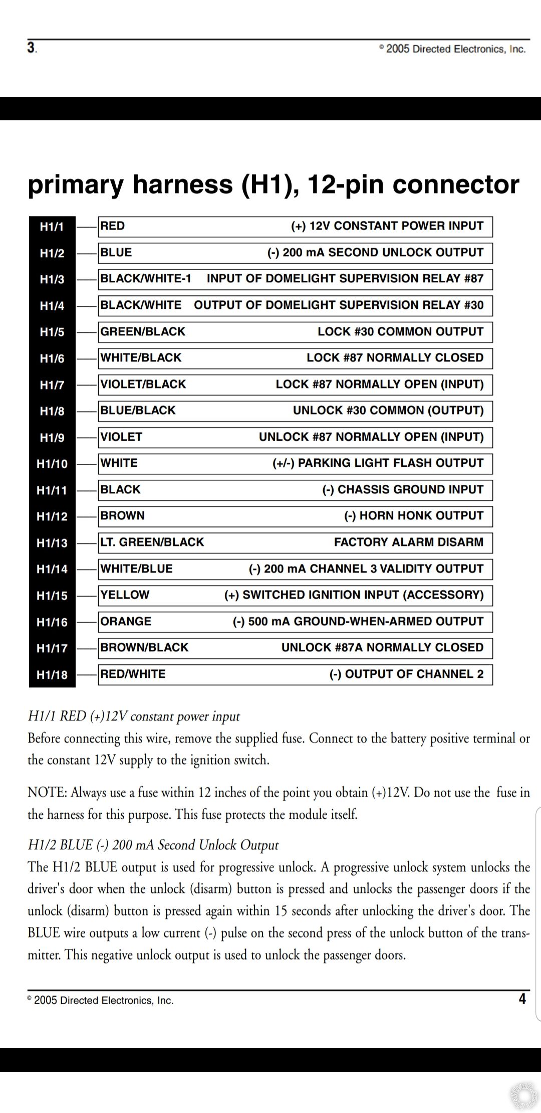
Both (H1/7) and (H1/9) #87 normally open wires to +12v constant.
Both (H1/6) and (H1/17) #87A normally closed wires to chassis ground.
Connect (H1/5) Lock 30 to one actuator wire and the (H1/8) Unlock #30 to the other actuator wire.
-------------
Steve G
Posted By: jlutz455
Date Posted: August 26, 2019 at 7:00 PM
Thanks for the help and quick response Steve! I have to travel for work this week but will try it his weekend.
Posted By: jlutz455
Date Posted: August 29, 2019 at 9:08 PM
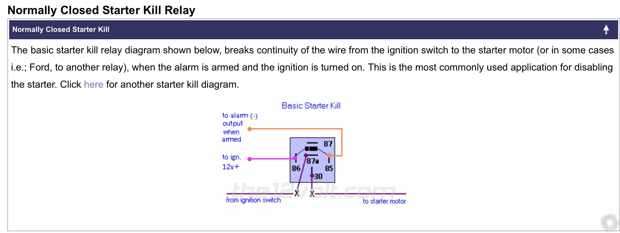
Steve...I setup a bench test hooking up the wires as you mentioned and it works great. Another question is the H1/16 orange wire called (-) 500 ma ground when armed. Is that for a starter kill when armed and I should wire like this...
Posted By: iskidoo
Date Posted: August 29, 2019 at 9:51 PM
Glad to hear that. That diagram is exactly how you should wire it. Good job searching the site for the answer. Looks like you are on the right track.
-------------
Steve G
Posted By: jlutz455
Date Posted: August 30, 2019 at 9:40 AM
Great..thank you again!! I always do a search first before asking questions as most the time the answer is already somewhere in the forum.
I'll just have to buy some more relays. I only have 1 tyco SPDT and looks like I'll need a total of 3 for my setup..trunk release, horn, and now starter kill.
Posted By: jlutz455
Date Posted: September 04, 2019 at 7:31 AM
More questions.. had lots of free time during our recent hurricane Dorian and hooked up the alarm and everything works great! Just need to do the starter kill and horn once the relays arrive.
Would like to add the progressive lock feature ( noted as H1/2 blue wire) but not sure how to go about it.
Posted By: iskidoo
Date Posted: September 04, 2019 at 5:09 PM
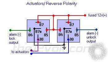
I think that would complicate things a bit. Normally you would connect 2nd unlock to the entire existing system that unlocks all doors at one time. Then you would isolate the drivers door from the rest and connect that to the regular unlock output. That would require another set of relays to control the driver actuator. This 211HV unit having built in relays makes it more difficult. You would need a 451M or a pair of relays wired to each individual actuator like this.
You could then wire your lock output from the 211HV to both pairs of relays. Then the unlock would wire to the drivers pair of relays and the 2nd unlock wire would go to the passenger side pair of relays.
Essentially you would no longer be using the 211HV internal relays to operate the actuators. You would be using external relay pairs for each side. The reason being that the lock output needed from the 211HV to control the passenger side relay pair is internal and I cant think of any way to get a locking output for the 2nd actuator.
Maybe there is a way to do it keeping the current setup but I am not able to think of it. Hopefully someone else may be able to chime in if they can figure out how to do it.
Personally I would just keep them the way they are due to the added work involved, but that is up to you.
Good luck. ------------- Steve G
Posted By: Ween
Date Posted: September 04, 2019 at 8:00 PM
Disconnect the unlock side of the passenger door actuator. Add a SPDT relay. Connections to the relay: Terminal 30 to Unlock side of passenger door actuator, Terminal 87A to Ground
(can use same ground as H1/6 & H1/17), Terminals 87 & 86 to Battery (can use same battery as H1/7 & H1/9), Terminal 85 to second unlock output (H1/2).
Posted By: jlutz455
Date Posted: September 05, 2019 at 7:29 AM
Thanks guys for the input and help! I'll hook it up per Ween's suggestion. Looks pretty straightforward and let you know.
|