This is for EWS disabled vehicles, automatic transmission.
I wanted to install a remote starter into my car but all the instructions I found where pretty confusing, partly incorrect or otherwise inadequate for a novice.
With this tutorial, you'll be able to install a remote starter even if you're a noob like myself.
The only thing is that is specific about this installation is that I already have the EWS module disabled on my DME. This avoids the trouble of bypass module and foregoing one of the keys.
You can find out online how to disable EWS or you can do it on ebay for less than $100.00.
In the future I might do it on a BMW with EWS module, but for now I just did ot on my parts car without EWS.
I'm in Canada so I bought this module
https://www.canadiantire.ca/en/pdp/prostart-5-button-2-way-led-remote-starter-0340793p.html
It's pretty hard to beat on price, $100 CAD which is probably around $70 USD. 2 way starter with 5 buttons.
I'm not going to cover the removal of the panels, it's pretty simple and already explained, just google if you need.
Here's the information you need in case you know nothing about starters like I did a few days ago.
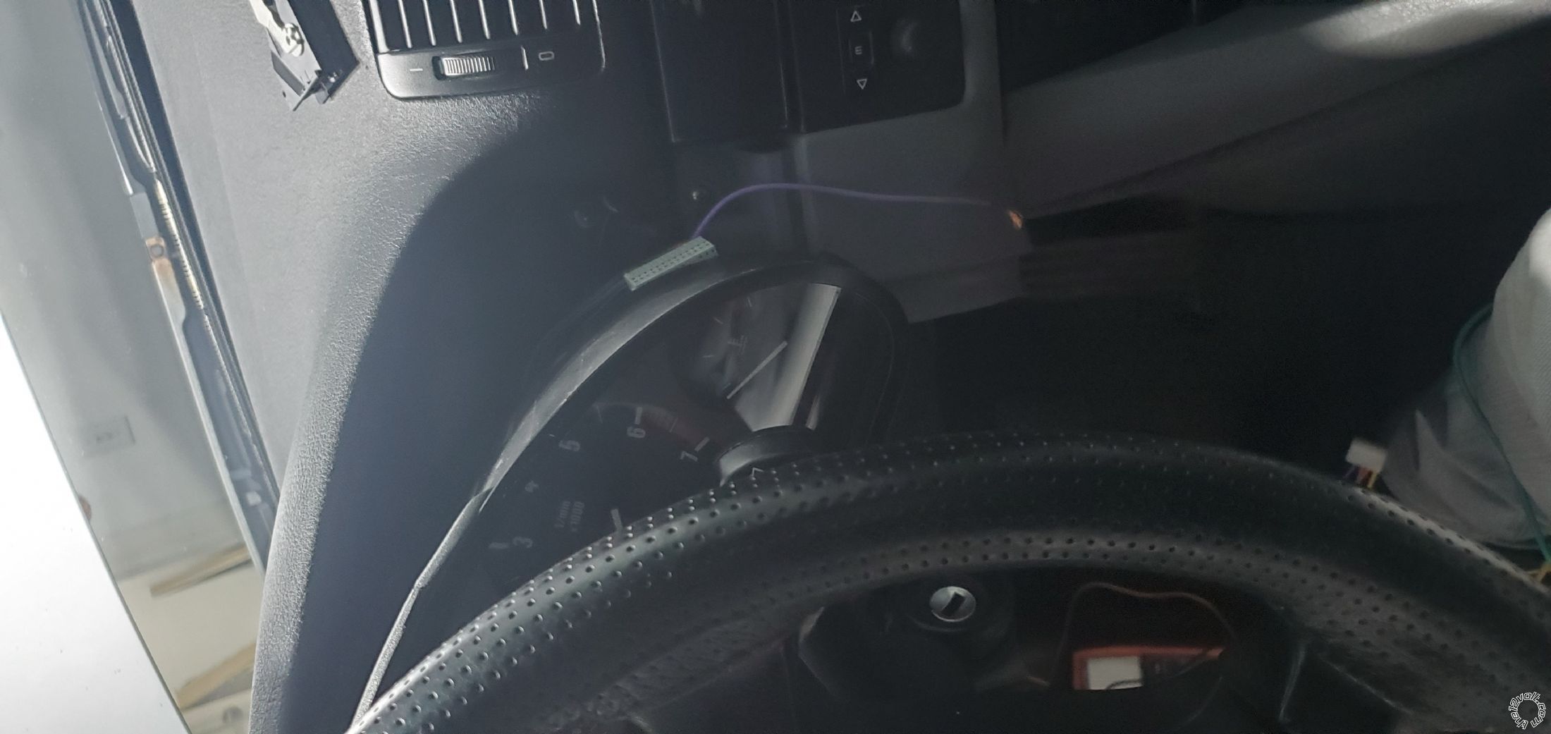
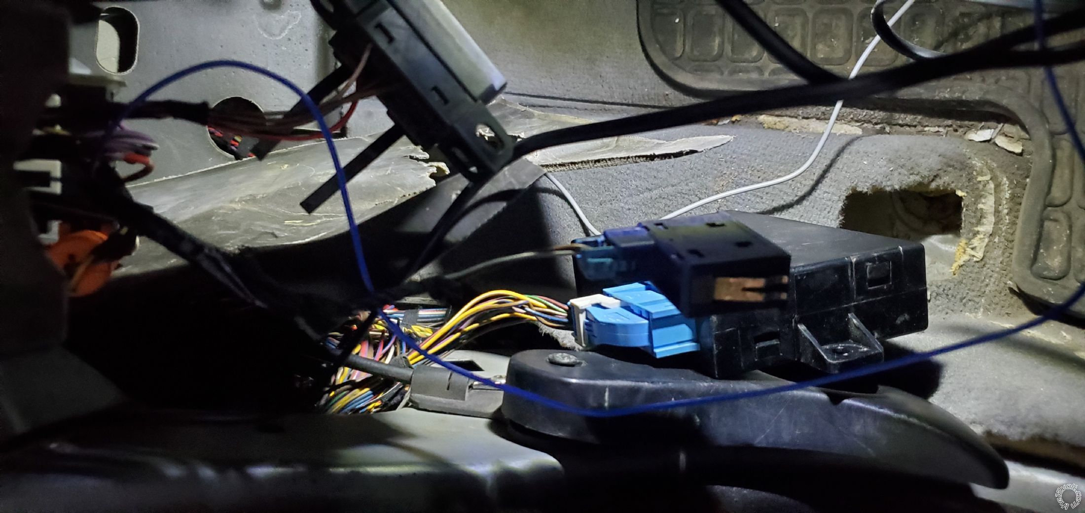
First, we're going to work with the ignition switch. This is where the most important things will take place.
I guess the relays differ somewhat for E39s based on the model and year.
You can find spinouts for your switch on this website:
https://www.newtis.info/tisv2/a/en/e39-528i-lim/components-connectors/components/f-fuses/fuses/f35-fuse/q-S2
Even though I selected my car, my ignition switch wires were a bit different.
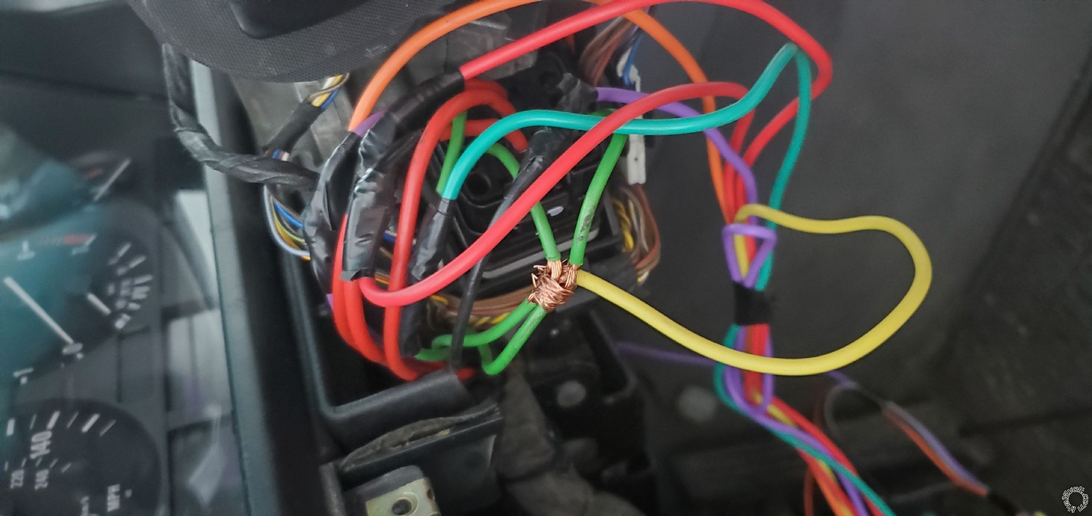
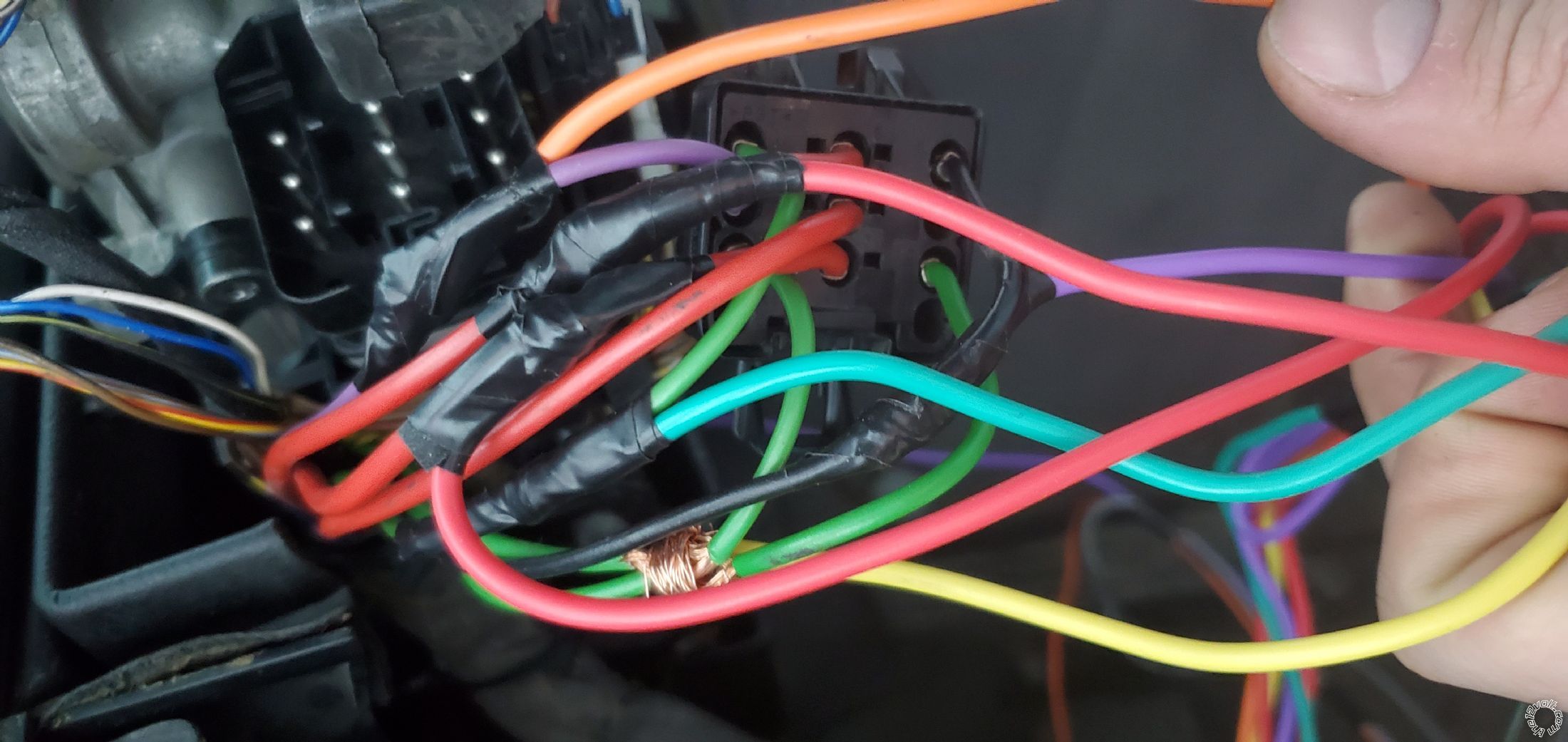
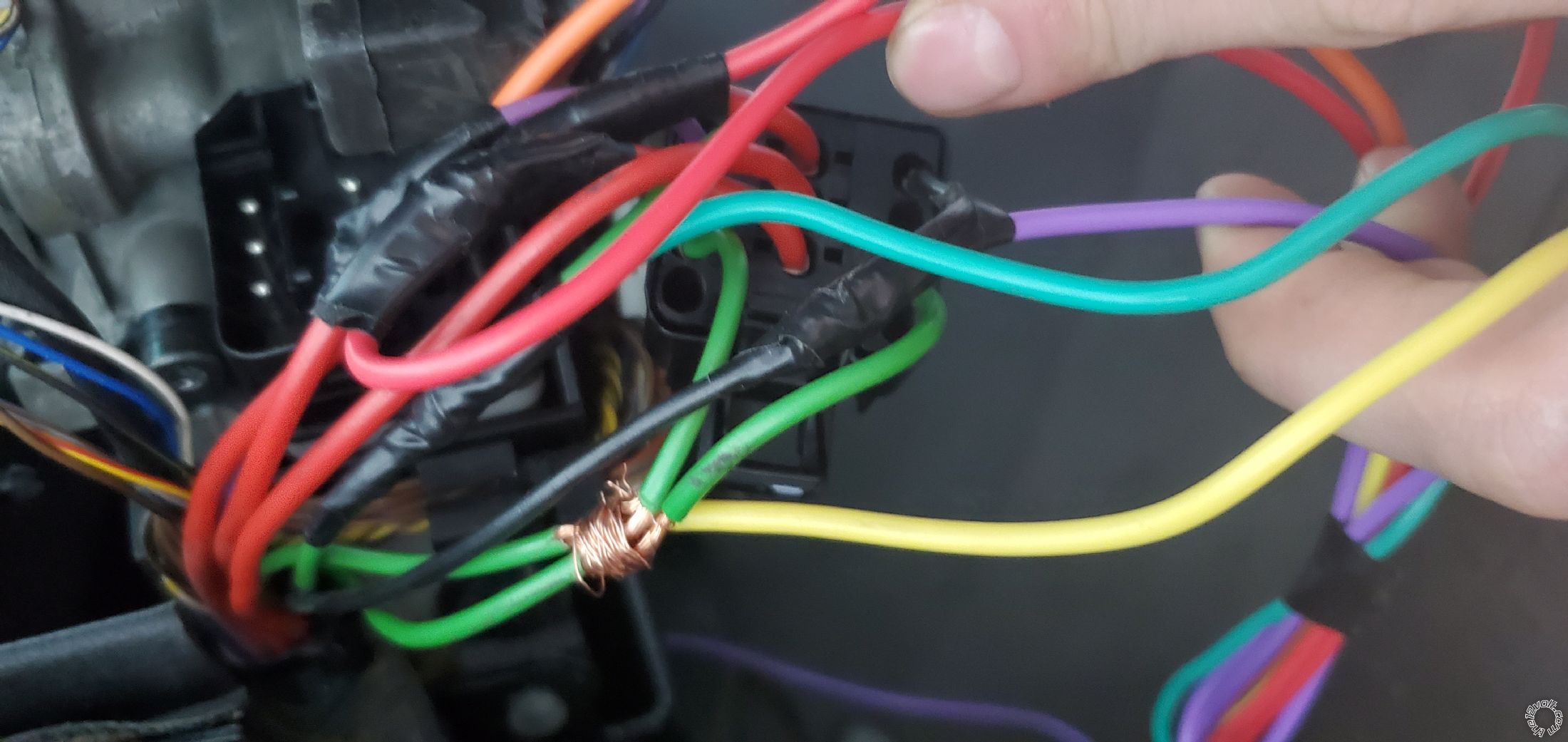
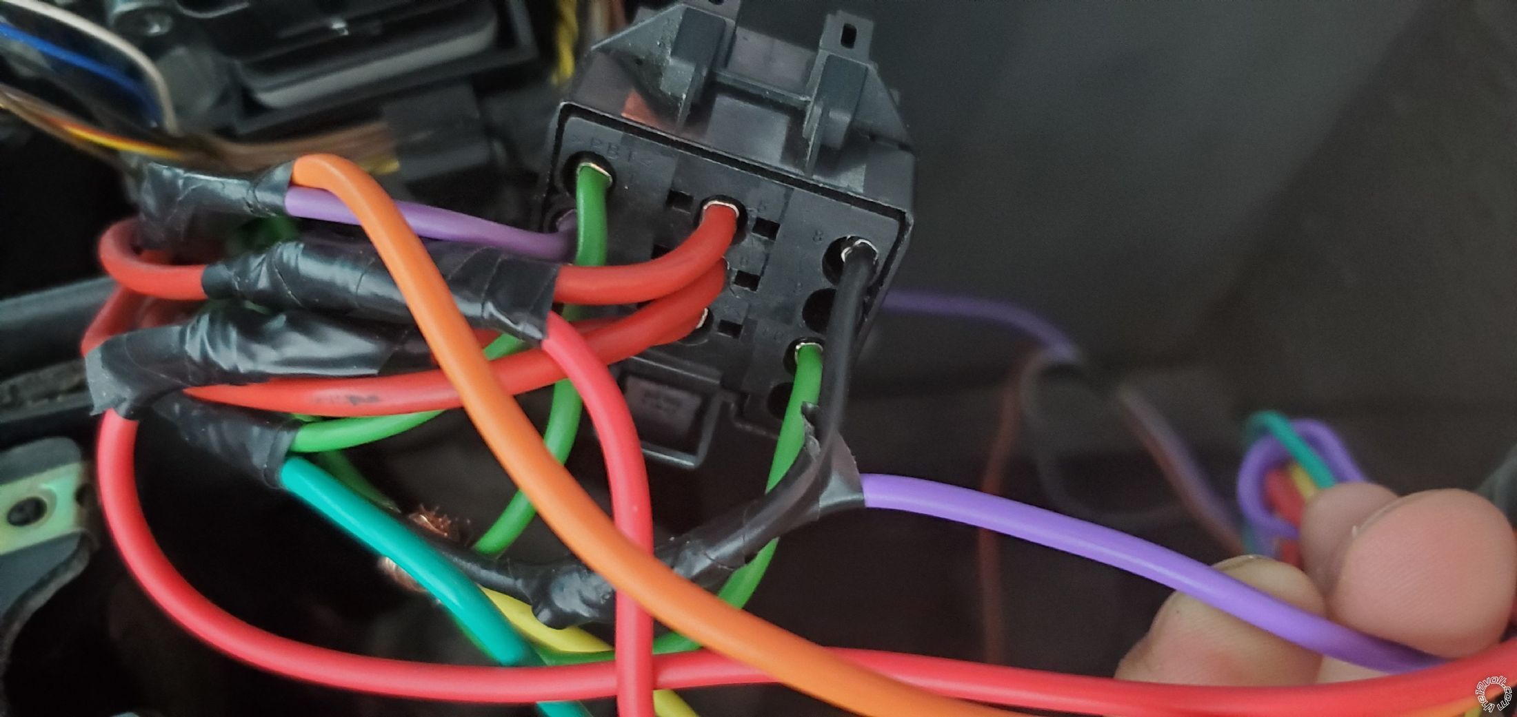
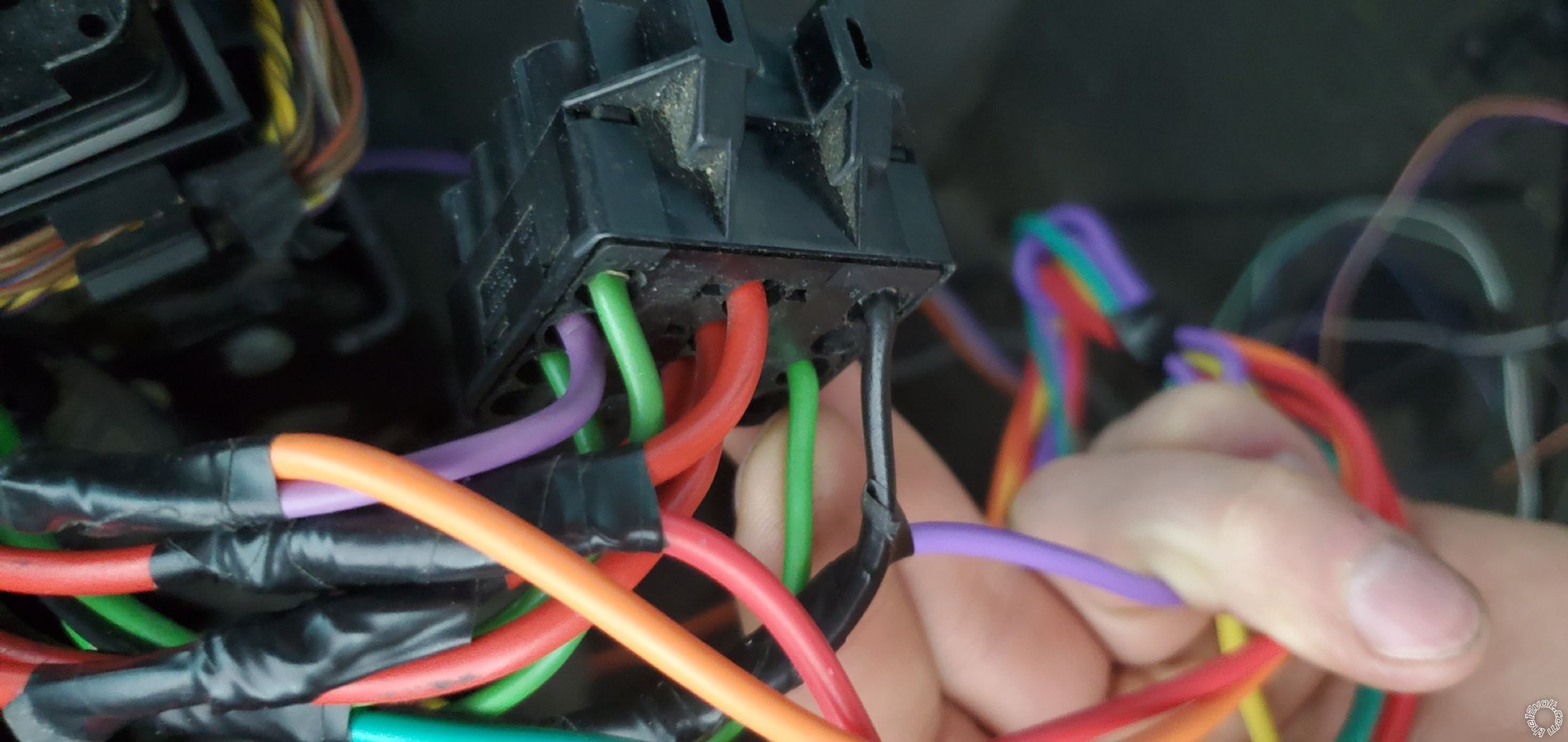
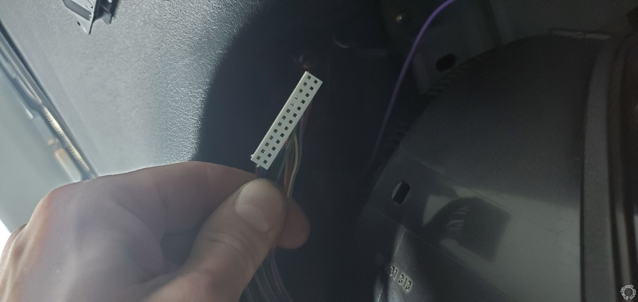
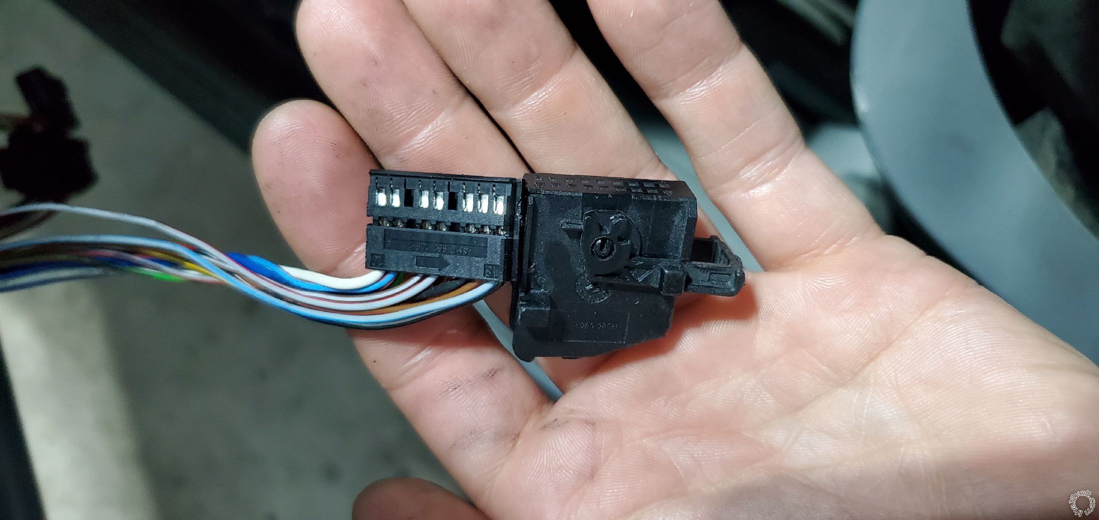
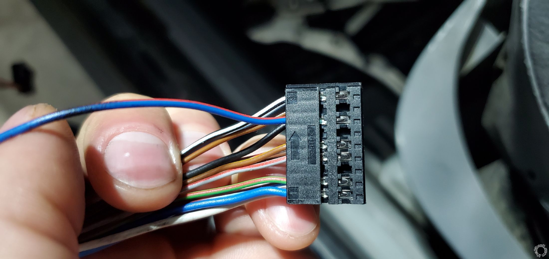
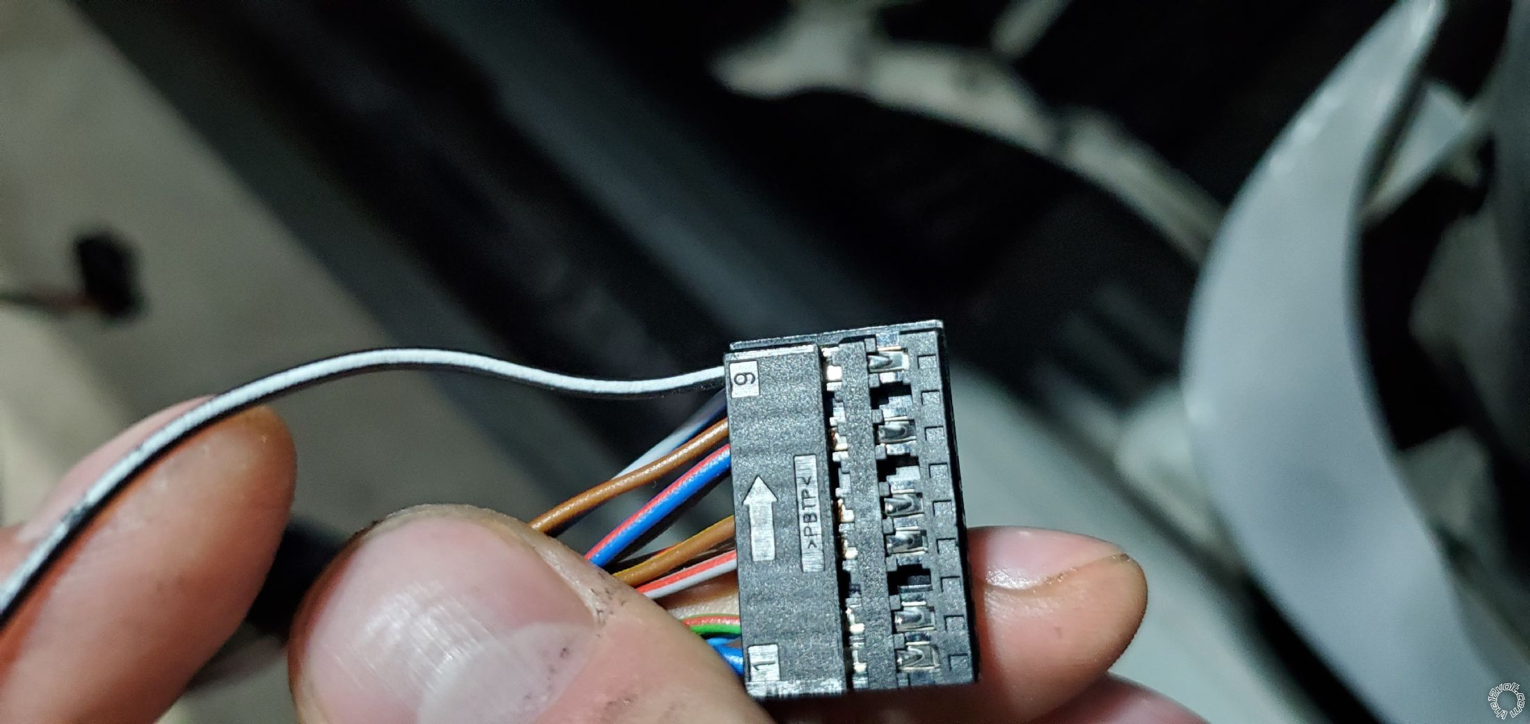
Ignition switch is connector X33
My ignition switch connections:
Pin 1, 3 and 10 are green wires that I understood are all ignition.
I connected the 2 of them together to the yellow (ignition) wire from the module. I connected the third one to thr "5th relay" wire having set the jumper to "ignition 2" previously.
I could've powered the first two green wires separately, but I didn't bother.
You can actually connect all 3 ignition wires together and it will still work fine.
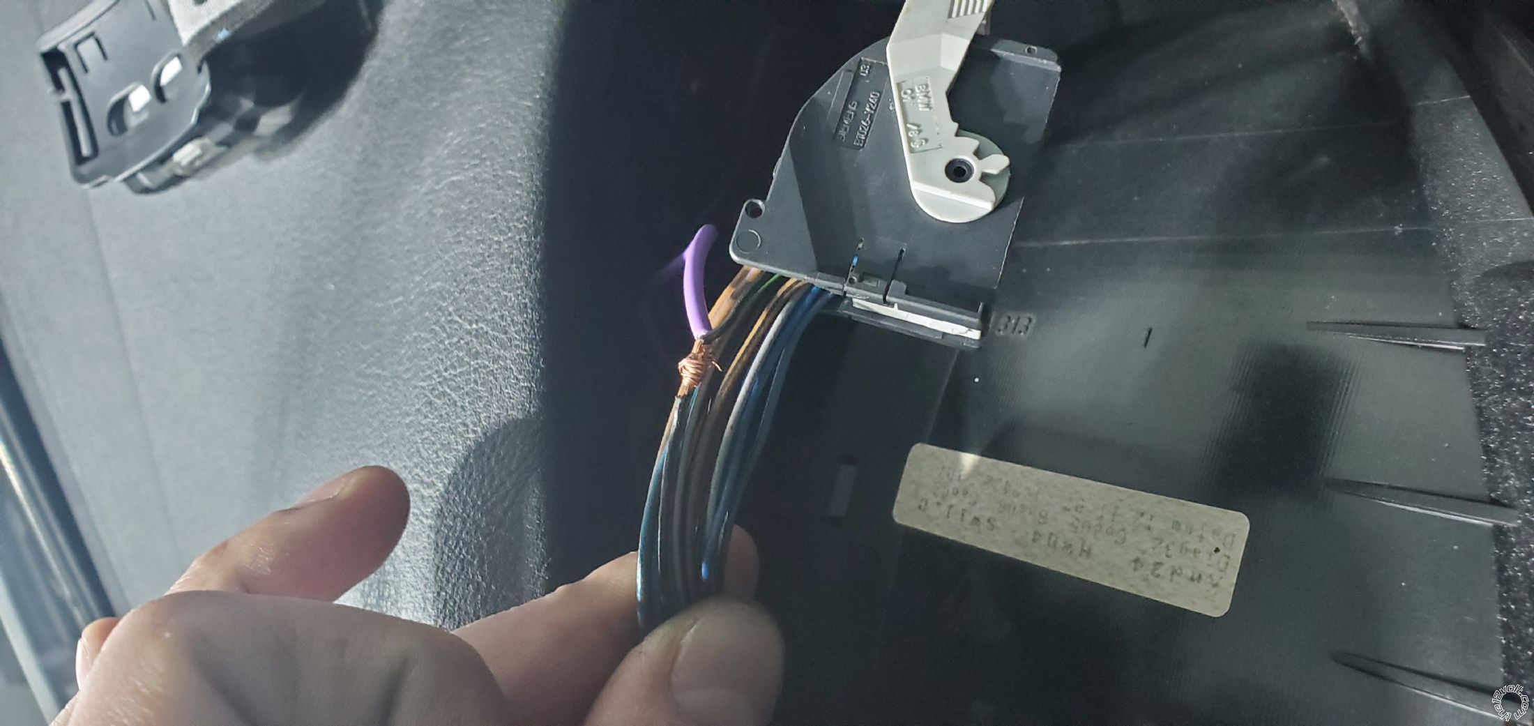
Pin 2 is a purple wire I understood to be accessories, so I connected it to the orange wire on the module.
Pins 5, 6 and 7 are all red power wires, 12 volts constant. I spliced wires on pin 5 and 7 and connected them separately to 2 red wires from the starter module. I left red wire on pin 6 intact.
Pin 8 is a black starter wire, so I connected it to the purple starter wire on the module.
Pin 9 is empty
Pin 10 I already covered
Pin 11 is empty
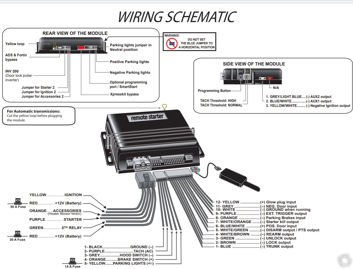
This is just to illustrate the module I'm working this.
So the first connector with 6 pins is taken care off.
Also on this starter you gotta cut the yellow loop for automatic transmissions.
Moving on to the second connector, 5 pin.
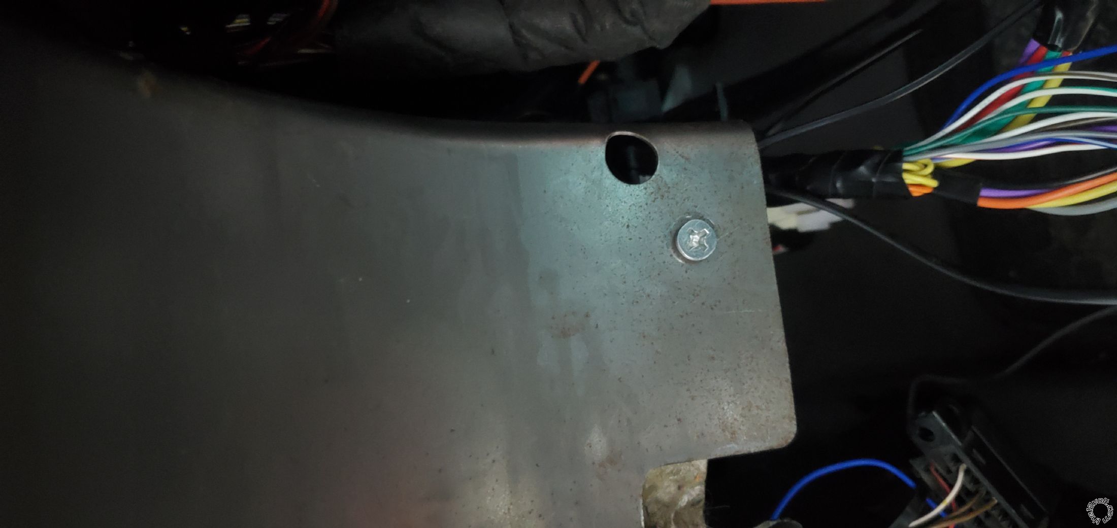
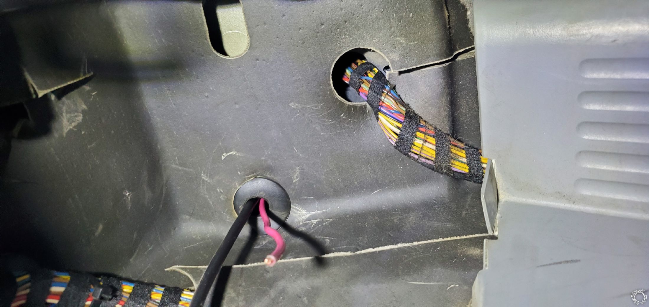
First pin is ground, pretty simply. You can drill a hole and put a screw or first one already existing.
I drilled an extra hole.
You can stop here if all you want is to start your vehicle.
Now pin 2 on this remote is for tach wire.
Looks.like lots of remotes have the option of wireless setting, including this one. However I used a wire.
Lots of tutorials recommend running your wire into the diagnostic post under the hood. I don't think this is very practical or needed.
Just use pin 6 on Connector X11175. It's the connector on your right side of the display.
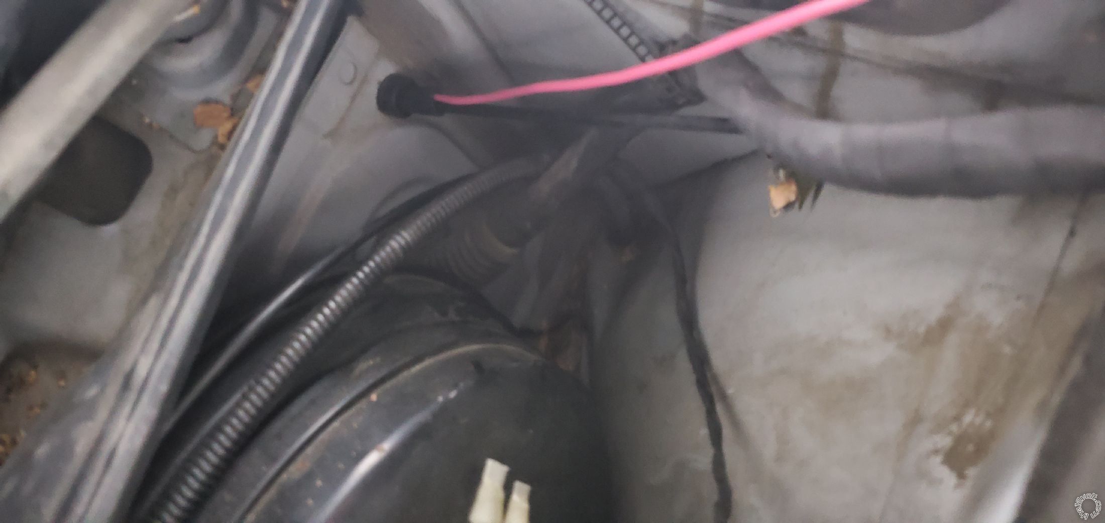
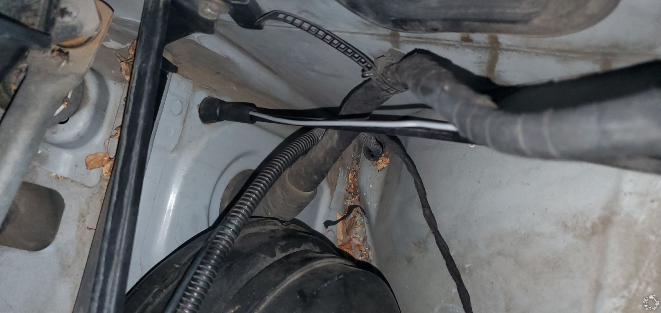
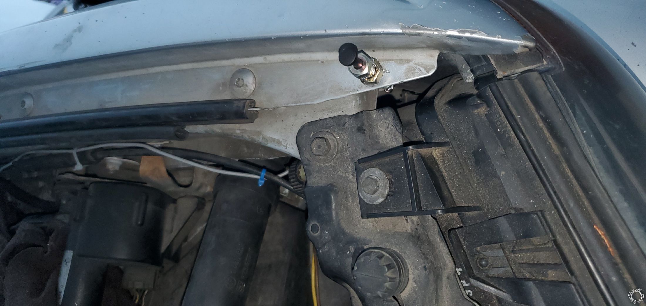
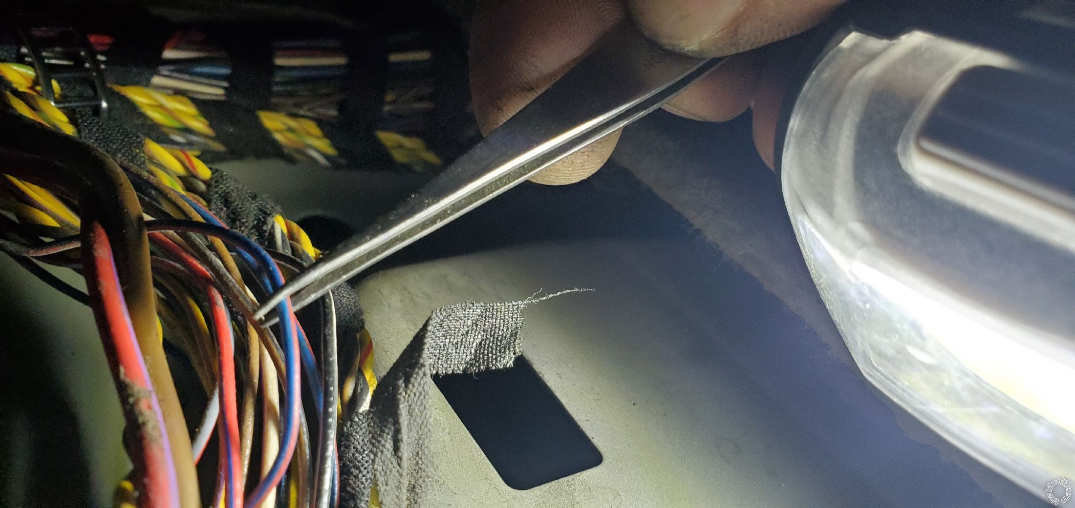
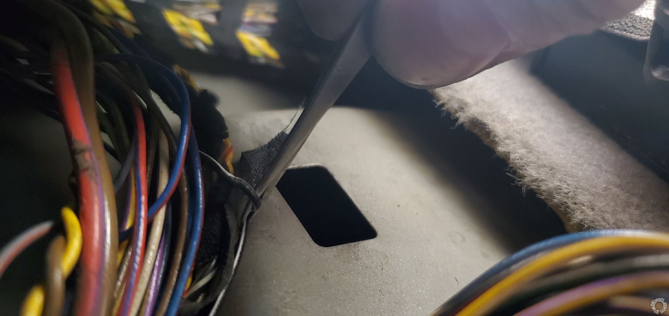
Now we move to the next wire, hood pin.
It's needed for programming the module so I installed it. If your vehicle was started from the remote, it will shut off if you open the good. The vehicle also won't start from remote if the hood is opened.
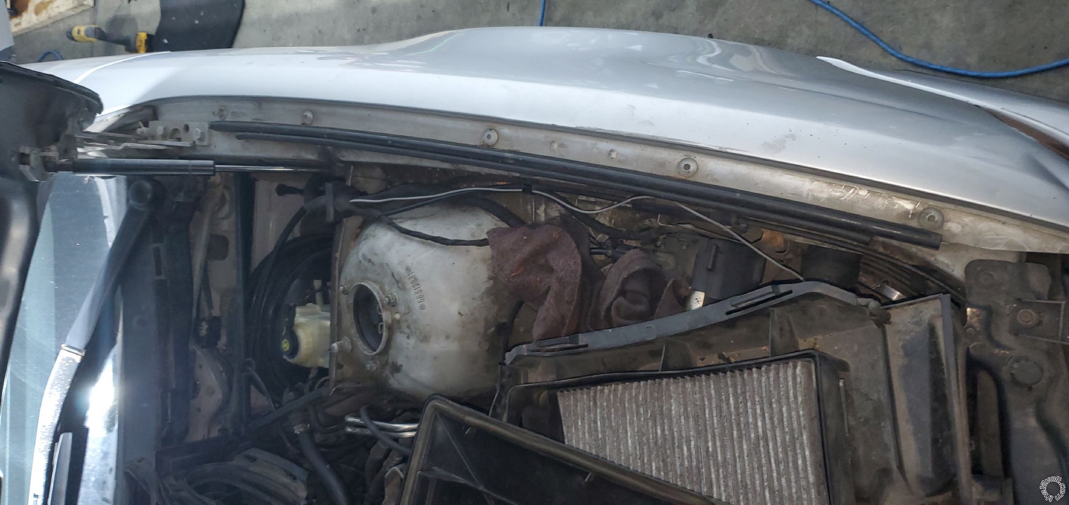
You run the wire under the hood like this
Moving on to break pedal wire.
It's grey/brown color. When the car is started, pressing the brake pedal will turn it off.
It's also needed to enter programming mode. When entering the programming mode, turn the key the first position, otherwise the break light will not work.
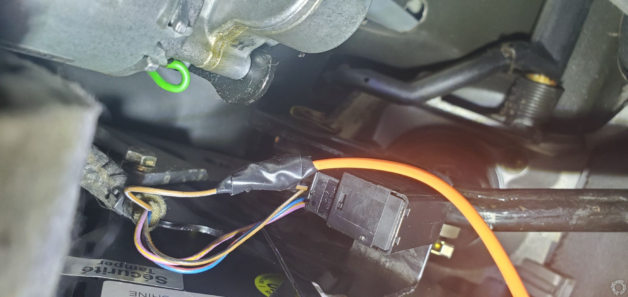
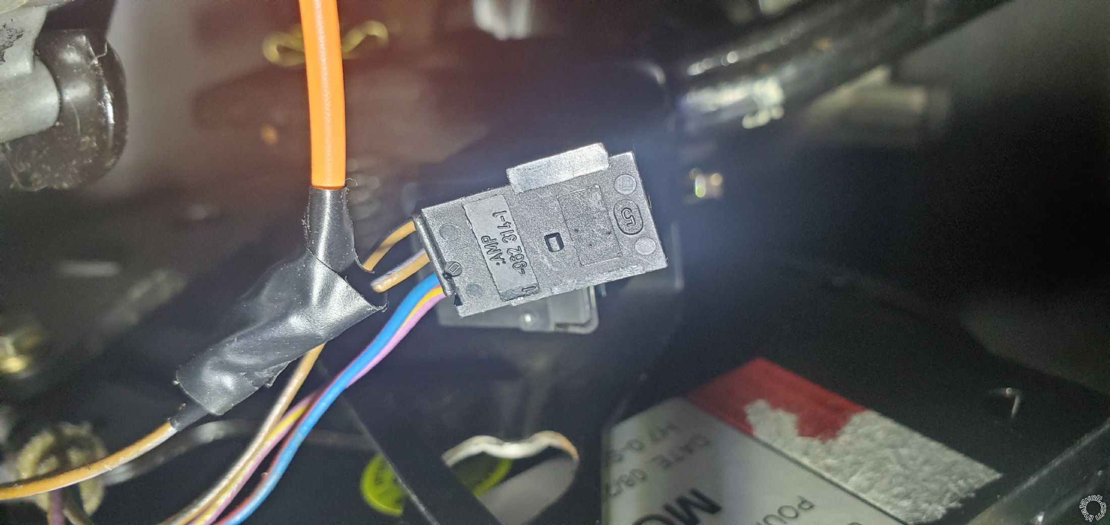
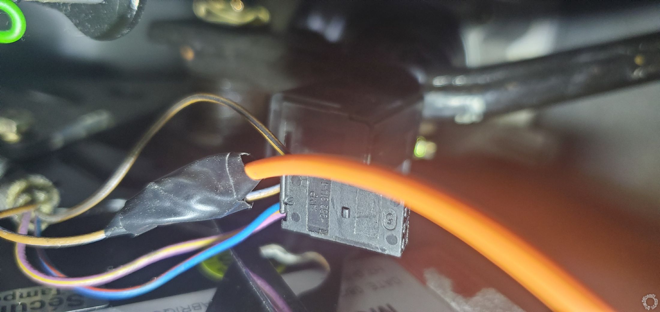
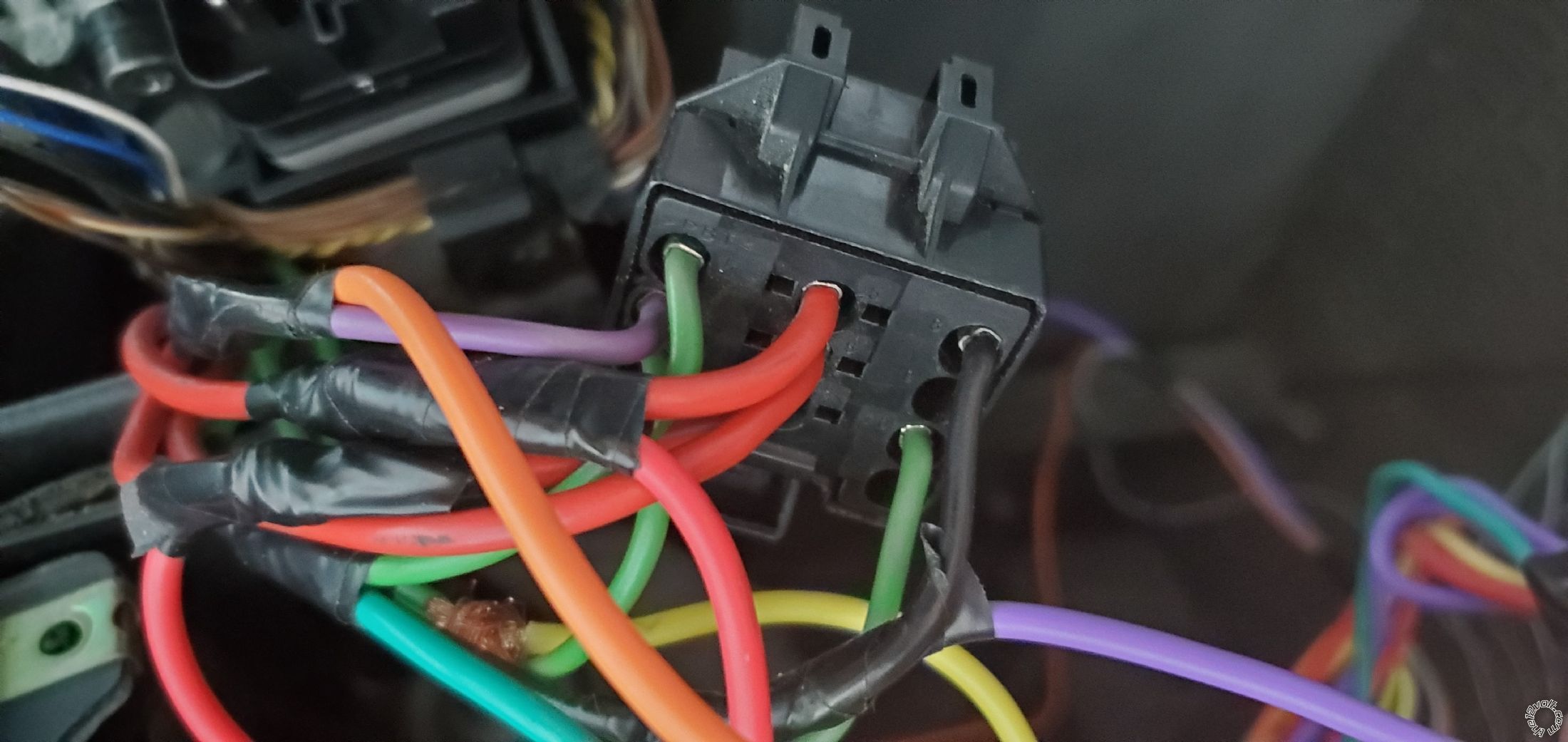
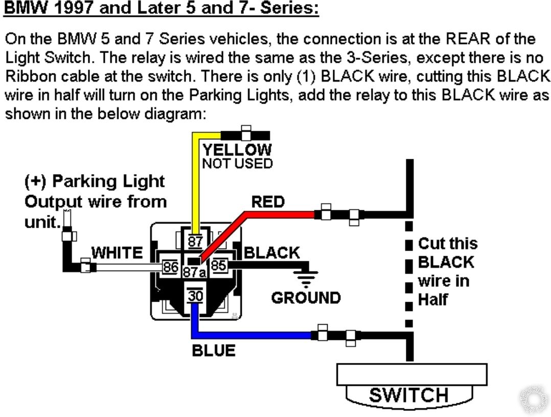
Now for the parking lights it's a bit complicated. You will need a single post single throw relay. Basically has to have terminals 30, 85, 86, 87 and 87a.
You cut the black wire behind the light switch and connect like this
Well now the first two connectors, 5 and 6 pins are done.
Now the last 12 pin connector.
Pin 1 is the blue wire on my remote.
You gotta connect it to the grey wire at the trunk switch. Simple.
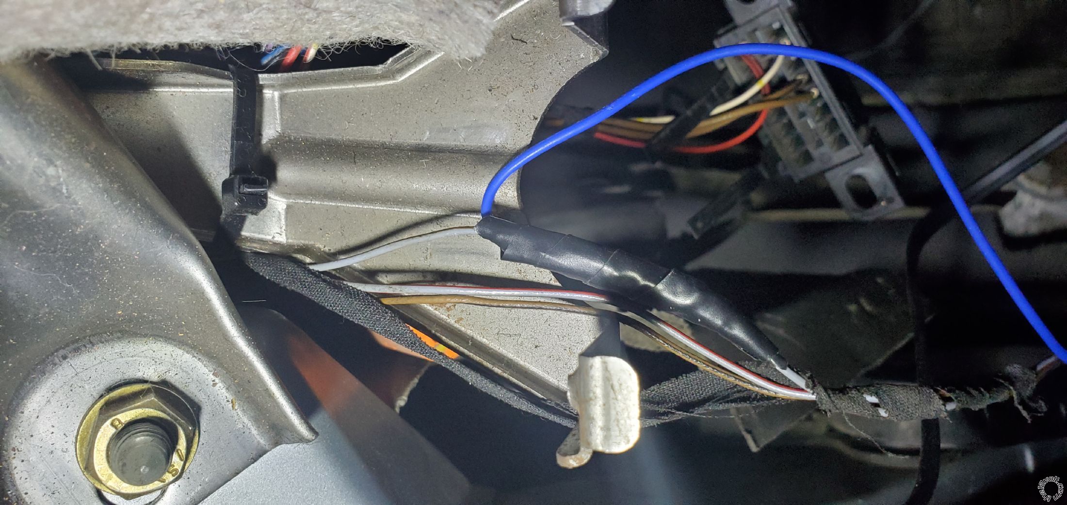
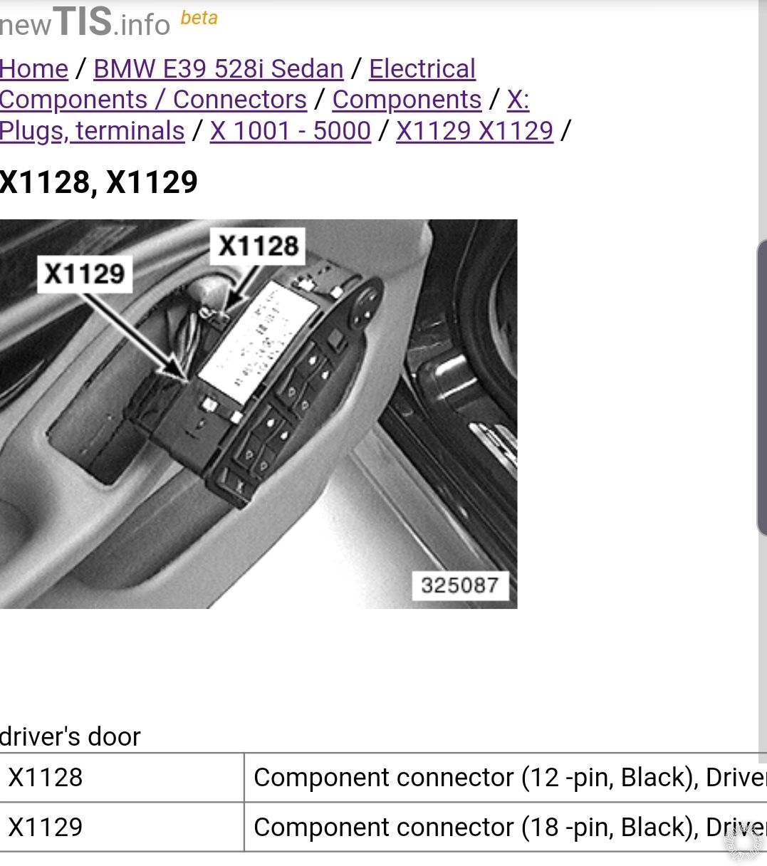
Pin 2 and 3 are lock and unlock wires. They can be found inside the door or in the footwell area. Inside the door it's connector X1129
Pik 7 is to lock the doors, pin 9 is to unlock.
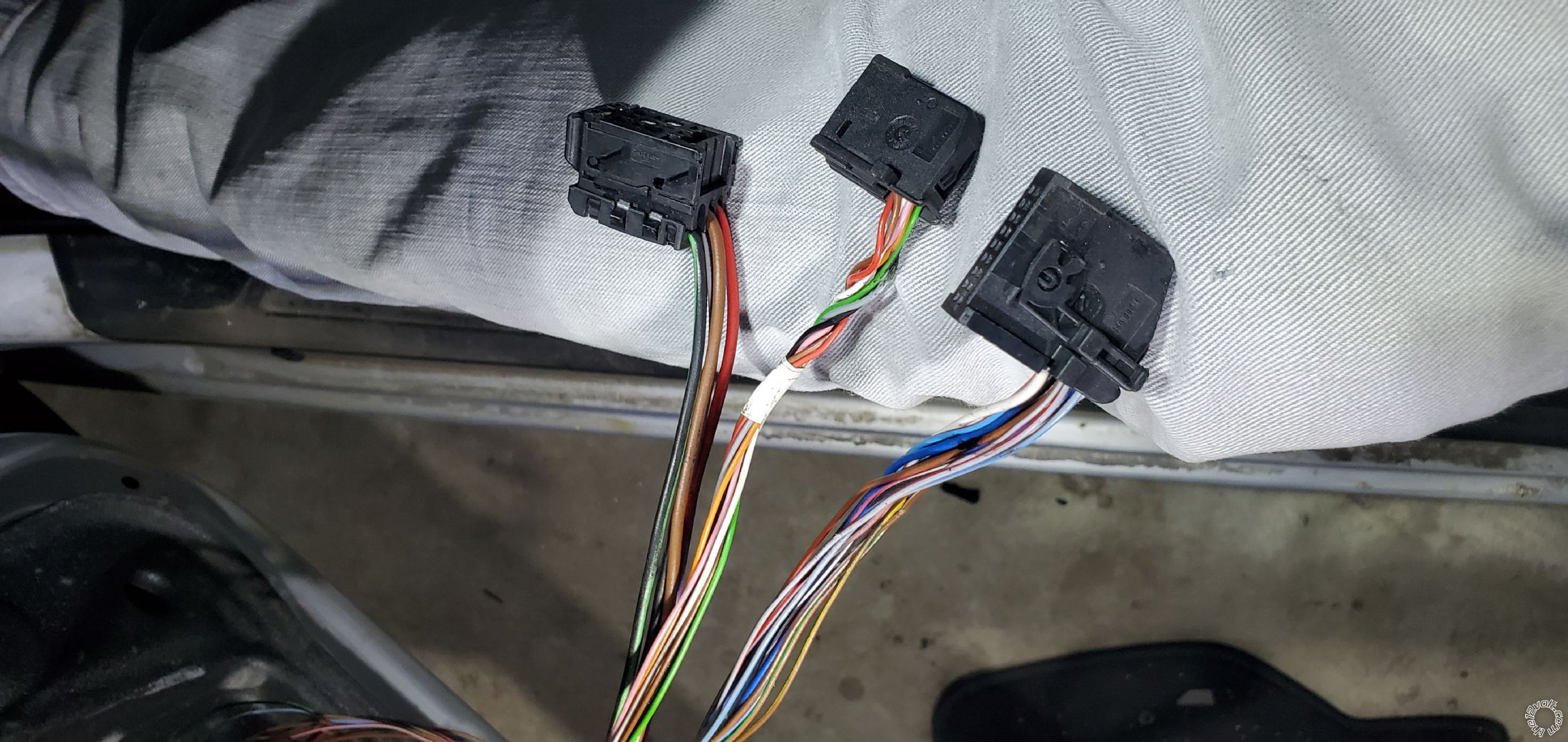
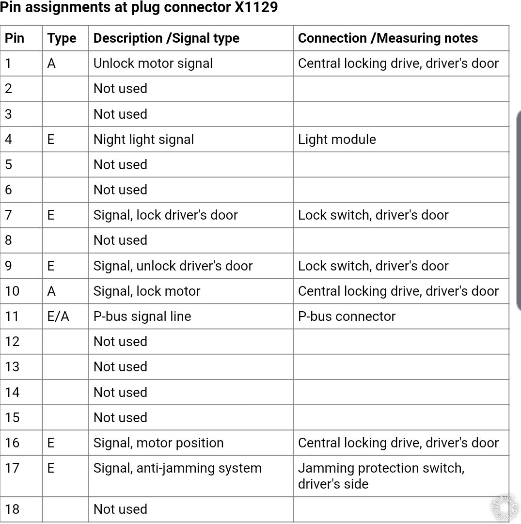
Blue and red is to lock, black and white is to unblock
The same wires in footwell area
Pin 4 and 5, arm and disarm, are not needed. Lock and unlock integrate that function.
Please critique my write up so I can take pictures and add explanations / test things while everything is still apart in my car.