2015 Nissan Altima PTS, Viper 4806V 2-Way
Printed From: the12volt.com
Forum Name: Car Security and Convenience
Forum Discription: Car Alarms, Keyless Entries, Remote Starters, Immobilizer Bypasses, Sensors, Door Locks, Window Modules, Heated Mirrors, Heated Seats, etc.
URL: https://www.the12volt.com/installbay/forum_posts.asp?tid=145792
Printed Date: May 14, 2026 at 9:45 AM
Topic: 2015 Nissan Altima PTS, Viper 4806V 2-Way
Posted By: aguilarpro
Subject: 2015 Nissan Altima PTS, Viper 4806V 2-Way
Date Posted: November 19, 2019 at 7:56 PM
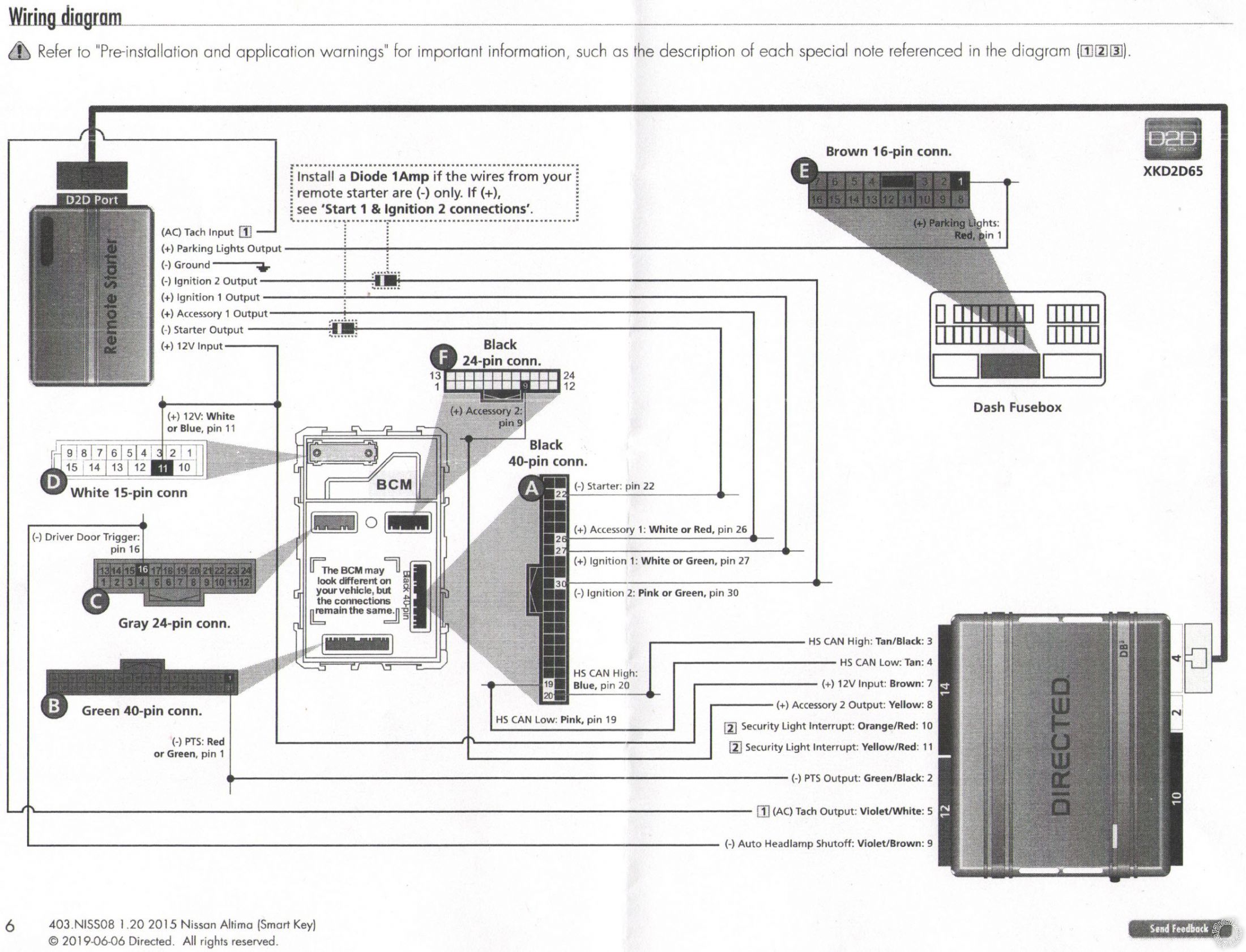
I'm hoping someone can check my work here. I'm in the process installing this alarm on my Nissan Altima 2015 Push To Start. I have everything almost gathered up but I have some doubts as what else is needed to be connected on the alarm side. I have the DB3 bypass module along with the wiring applicable to the vehicle so I'm covered there and partial wiring from the Remote start side. I have highlighted the wire I will be connecting based on the diagram provided with the DBALL 3 but I do not have the complete schematics and I believe I'm still missing some basic connections. Also, the use of Diodes appears to not be necessary in my case but mentions to see "Start 1 & Ignition 2 Connections" which in this case Ign2 is marked with a Diode but the Alarm side is positive. I appreciate any help that I can get.
 ------------- Honda Accord 2008 EX-L 2.4 S
Replies:
Posted By: aguilarpro
Date Posted: November 20, 2019 at 10:20 PM
Let me know if you guys have installed or are familiar with this system, I appreciate any help I can get. Thanks!
-------------
Honda Accord 2008 EX-L 2.4 S
Posted By: dcman41
Date Posted: November 22, 2019 at 12:59 PM
in your situation you will be using both + and - polarity for your ignition wires. no relays are needed because your remote start brain supports both. use the respective wires on the 24 pin harness with a diode placed in line and the stripe facing towards the remote star on all negative polarity ignition wires. Use Pin 1 / 24 (pink/white ) - ignition 2 flex output. Pin 21/24 (violet / yellow) - starter output . Use the heavy the gauge harness pink wire for + ignition and orange for + accessory. good luck, hope this helps
Posted By: dcman41
Date Posted: November 23, 2019 at 7:26 AM
only connect the wires shown in the DB3 diagram. your db3 bypass will handle your brake shutdown, door locks, trunk release, etc...
Posted By: aguilarpro
Date Posted: December 02, 2019 at 8:06 PM
So, if I'm reading this right, I don't need wires 2, 3, 5 & 7 from Remote Start, 8-pin connector? What about Main harness 6-pin connector(Do I need wire 4 - White/Brown)?
-------------
Honda Accord 2008 EX-L 2.4 S
Posted By: dcman41
Date Posted: December 05, 2019 at 9:51 AM
yes, that is correct, you dont need the wires you specified and you also dont need the white/brown wire either
Posted By: aguilarpro
Date Posted: December 06, 2019 at 4:56 PM
Does the heavy wires (ing & acc, 8-pin) go to those small wires at the car computer? Or should I use those from the 24 pin? They have different polarities however as can be seen in the diagrams.
-------------
Honda Accord 2008 EX-L 2.4 S
Posted By: aguilarpro
Date Posted: December 07, 2019 at 3:33 PM
I installed the heavy gauge wires to the small ones and right now I'm getting "I-Key System Error: See Owner's Manual" when attempting remote start. I know this is not the bypass causing it as I have the key close and it still says the same thing. It perhaps is a wire from the bypass that needs something else. As illustrated above, I did not wire the ones with the #[2] symbols on the 12-pin connector of the D2D, perhaps this is where my problem lies.
-------------
Honda Accord 2008 EX-L 2.4 S
Posted By: aguilarpro
Date Posted: December 09, 2019 at 6:59 PM
dcman41 wrote:
yes, that is correct, you dont need the wires you specified and you also dont need the white/brown wire either
I'm suspecting this could be a hood latch that is preventing a remote start since this is a D2D option? Please let me know what you think. I see that the remote flashes Red & Orange during remote start process and then Flashing green for actuating the brain to remote start but then it gets the I-Key error and then tries again 2 more times with a total of 3 times. Thanks in advance. ------------- Honda Accord 2008 EX-L 2.4 S
Posted By: aguilarpro
Date Posted: January 21, 2020 at 12:15 PM
Somebody please help :(
-------------
Honda Accord 2008 EX-L 2.4 S
Posted By: kreg357
Date Posted: January 21, 2020 at 3:34 PM
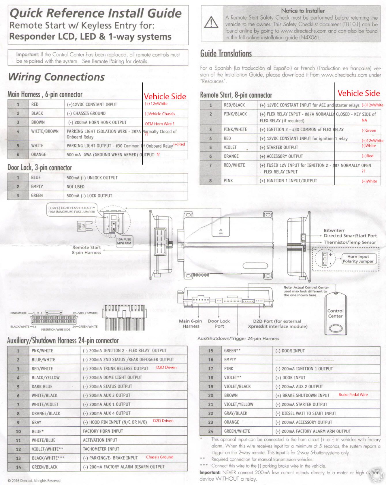
OK, here is the wiring from the 4806 to the Altima.
H/1 RED (+)12VDC CONSTANT INPUT +12V Constant
H/2 BLACK (-) CHASSIS GROUND Chassis Ground
H/3 BROWN (-) 200mA HORN HONK OUTPUT GREEN (-) @ HORN SWITCH, YELLOW 6-PIN PLUG, PIN 3
H/4 WHITE/BROWN LIGHT FLASH ISOLATION WIRE Not Used
H/5 WHITE PIN 30 of LIGHT FLASH RELAY set to (+) RED (+) dash fuse box, brown 16 pin plug, pin 1
H/6 ORANGE 500 mA GROUND WHEN ARMED OUTPUT Not Used
Remote Start, 8-pin connector
1 RED/BLACK (+) 12VDC CONSTANT INPUT +12V Constant
2 PINK/BLACK (+) FLEX RELAY INPUT 87A Not Used
3 PINK/WHITE (+) IGNITION 2 set to IGN2 Not Used
4 RED (+) 12VDC CONSTANT INPUT +12V Constant
5 VIOLET (+) STARTER OUTPUT Not Used
6 ORANGE (+) ACCESSORY OUTPUT White or Red at BCM Black 40 Pin plug, Pin 26
7 RED/WHITE (+) 12VDC CONSTANT INPUT Not Used
8 PINK (+) IGNITION 1 INPUT/OUTPUT White or Green at BCM Black 40 Pin plug, Pin 27
Auxiliary/Shutdown Harness 24-pin connector
1 PNK/WHITE (-) 200mA Ignition 2/Flex OUTPUTPink or Green at BCM Black 40 Pin plug, Pin 30 with 1N4001
2 BLUE/WHITE (-) 200mA 2ND STATUS /REAR DEFOGGER OUTPUT NU
3 RED/WHITE (-) 200mA TRUNK RELEASE OUTPUT NU
4 BLACK/YELLOW (-) 200mA DOME LIGHT OUTPUT NU
5 DARK BLUE (-) 200mA STATUS OUTPUT NU
6 WHITE/BLACK (-) 200mA AUX 3 OUTPUT NU
7 WHITE/VIOLET (-) 200mA AUX 1 OUTPUT NU
8 ORANGE/BLACK (-) 200mA AUX 4 OUTPUT NU
9 GRAY (-) HOOD PIN INPUT (NC OR NO) supplied by bypass module if car has Factory Alarm
10 BLUE* FACTORY HORN INPUT (Use Jumper to set polarity) NU
11 WHITE/BLUE ACTIVATION INPUTNU
12 VIOLET/WHITE** TACHOMETER INPUT supplied by bypass module
13 BLACK/WHITE*** (-) NEUTRAL SAFETYChassis Ground
14 GREEN/BLACK (-) 200mA FACTORY ALARM DISARM OUTPUT NU
15 GREEN** (-) DOOR INPUT NU
16 EMPTY ------------------------------------
17 PINK (-) 200mA IGNITION 1 OUTPUT NU
18 VIOLET** (+) DOOR INPUT NU
19 VIOLET/BLACK (-) 200mA AUX 2 OUTPUT NU
20 BROWN (+) BRAKE SHUTDOWN INPUT supplied by bypass module
21 VIOLET/YELLOW (-) 200mA STARTER OUTPUT to BCM Black 40 Pin plug, Pin 22 with 1N4001
22 GRAY/BLACK (-) DIESEL WAIT TO START INPUT NU
23 ORANGE (-) 200mA ACCESSORY OUTPUT NU
24 GREEN/WHITE (-) 200mA FACTORY ALARM ARM OUTPUT NU
Follow the DB3 guide for it's connections to the Altima. You might have to hardwire the Tach between the DB3 and the 4806. Depends on what Note 1 says.
Just so we don't overlook things...
The DB3 must be flashed with the 4.03 NISS08 firmware, presently at Version 1.20. Has this been done?
When you did the DB3 to vehicle programming after making all the connections, did it follow the steps and indications exactly?
The DB3 should handle the locks and alarm plus the transponder bypass funcions. It should also supply the Viper with the Brake,
Tach and Hood Pin signals via D2D. Do the door locks work via the Viper remotes?
-------------
Soldering is fun!
Posted By: aguilarpro
Date Posted: February 26, 2020 at 8:32 PM
Kreg, thank you for the information, I will check these wirings and see if I missed one from my initial hard wiring. The car locks and unlocks like normal; during the programming to vehicle, the flashing did not occur like it said when I performed the steps (it was very simple but I was not convinced one of the steps went through). It is possible that it did not through because my wiring was not correct or was not complete. I believe there may be a wiring that I did not connect from the list you supplied, I will verify and report.
-------------
Honda Accord 2008 EX-L 2.4 S
Posted By: aguilarpro
Date Posted: February 26, 2020 at 9:01 PM
Kreg, I checked my wiring really quick and found that I used the heavy gage remote start 8-pin wires #3 & #5 but I should have used the #1 Ignition 2 from the 24-pin connector, same for #21 Starter output, in this case the polarities will match the car's. This may have been the reason as to why I was puzzled that such heavy gage wires from the 8-pin would need to be connected to the small wires at the BCM. I will rewire per your instructions and report, since it is snowing, I may have to report at a later time. Thank you for your help.
-------------
Honda Accord 2008 EX-L 2.4 S
Posted By: aguilarpro
Date Posted: October 03, 2020 at 11:32 AM
Kreg,
I verified the wiring and everything looks good, I initially thought that I had used the heavy gage wires for the ones that have the diode but that was not the case. I verified the wiring and everything looks correct. I remember that the module did not flash the green light, is there a way to restart the programming side without flashing it to be able to follow the module programming again? I don't have access to reflash as the seller did that for me when he sold the unit to me. If I reset the DB3 module (if possible) will it loose the flash to the car? I think this is a flashing issue at this point, door lock/unlock and trunk release work, the only thing that is not working is the remote start, it looks like it tries to start, activates the accessories, the module receives the signal, flashes orange and red momentarily and then flashes green for maybe 5 seconds and then turns off.
The sequence of DB3 flashes when remote start button is pressed:
1. 3x green flahes.
2. 3x yellow and red flashes (interchangeably)
3. Multiple green rapid flashes, then goes back to green slow flashing and tries again 3 more times before it stops. In the process of the rapid flashes I get the I-Key System Error: See Owner's Manual.
The vehicle does not crank at all.
Here is the module programming instruction.
.jpg) ------------- Honda Accord 2008 EX-L 2.4 S
Posted By: kreg357
Date Posted: October 03, 2020 at 3:53 PM
Unfortunately, I'm not a DEI guy but you can do a "Soft Reset" as shown at the top of Page 15. This will get the DB3 ready to start the vehicle programming process again from the beginning. It will not affect the 403.NISS08 Ver 1.20 firmware loaded on the module.
-------------
Soldering is fun!
Posted By: aguilarpro
Date Posted: December 26, 2024 at 8:50 PM
Did not come back to confirm but after this was wired up accordingly, the programming sequence was executed and the car remote started fine.
-------------
Honda Accord 2008 EX-L 2.4 S
|